- •LIST OF ABBREVIATIONS
- •New Ignition Interlock Sidestand System
- •Current Ignition Interlock Sidestand System
- •Materials of Semi-Conductor and Emitting Color
- •Units of Mass:
- •Units of Volume:
- •Units of Force:
- •Units of Length:
- •Units of Torque:
- •Units of Pressure:
- •Units of Speed:
- •Units of Power:
- •Periodic Inspection:
- •Periodic Replacement Parts:
- •Basic Torque for General Fasteners
- •Throttle Grip Free Play
- •Idle Speed
- •Engine Vacuum
- •Water and Coolant Mixture Ratio (when shipping)
- •Valve Clearance
- •Clutch Lever Free Play
- •Engine Oil
- •Tread Depth
- •Air Pressure (when cold)
- •Chain Slack
- •Drive Chain 20-link Length
- •Standard Chain
- •Pad Lining Thickness
- •Sample Diagnosis Sheet
- •Poor Running at Low Speed
- •Poor Running or No Power at High Speed:
- •Wiring Connection
- •Idle Speed
- •Wiring Connection
- •Main Throttle Sensor Resistance
- •Inlet Air Pressure Sensor Output Voltage
- •Inlet Air Temperature Sensor Output Voltage
- •Water Temperature Sensor Output Voltage
- •Atmospheric Pressure Sensor Input Voltage
- •Output Voltage at Sensor
- •Wiring Connection
- •Throttle Sensor Resistance
- •Stick Coil Input Voltage at ECU
- •Input Voltage at ECU
- •Subthrottle Valve Actuator Resistance
- •Subthrottle Valve Actuator Input Voltage
- •Input Voltage at Actuator
- •FI Indicator LED Light Check
- •ECU Grounding Inspection
- •ECU Power Source Inspection
- •Testing Relay
- •Fuel Pressure
- •Fuel Pressure (idling)
- •Amount of Fuel Flow
- •Testing Relay
- •Injector Power Source Voltage at ECU
- •Output Voltage at Injector Connector
- •Injector Wiring Inspection
- •Choke Lever Free Play
- •Radiator Cap Relief Pressure
- •Thermostat Valve Opening Temperature
- •Camshaft Journal, Camshaft Cap Clearance
- •Camshaft Journal Diameter
- •Camshaft Runout
- •Cylinder Compression
- •Cylinder Head Warp
- •Valve/Valve Guide Clearance (Wobble Method)
- •Valve Seating Surface Outside Diameter
- •Valve Seating Surface Width
- •Cylinder Inside Diameter
- •Piston Diameter
- •Piston Ring/Groove Clearance
- •Piston Ring Groove Width
- •Piston Ring Thickness
- •Piston Ring End Gap
- •Clutch Plate Assembly
- •Friction Plate Thickness
- •Friction and Steel Plate Warp
- •Clutch Spring Free Length
- •Oil Pressure
- •Connecting Rod Bend
- •Connecting Rod Twist
- •Connecting Rod Big End Side Clearance
- •Crankpin Diameter
- •Crankpin Diameter Marks
- •Connecting Rod Big End Inside Diameter Marks
- •Crankshaft Side Clearance
- •Crankshaft Runout
- •Crankshaft Main Journal Diameter
- •Crankshaft Main Journal Diameter Marks
- •Crankcase Main Bearing Inside Diameter Marks
- •Shift Fork Ear Thickness
- •Gear Groove Width
- •Shift Fork Guide Pin Diameter
- •Shift Drum Groove Width
- •Rim Runout
- •Axle Runout/100 mm (3.94 in.)
- •Balance Weight
- •Link Pin Outside Diameter
- •Link Plates Outside Width
- •Rear Sprocket Warp
- •Pedal Position
- •Front Disc Thickness
- •Rear Disc Thickness
- •Disc Runout
- •Oil Level (fully compressed, without spring)
- •Fork Spring Free Length
- •Rebound Damping Adjustment
- •Spring Preload Setting
- •Spring Preload Adjustment
- •Table 1 Alternator Output Voltage
- •Table 2 Stator Coil Resistance
- •Rectifier Circuit Inspection
- •Charging Voltage
- •Crankshaft Sensor Peak Voltage
- •Connections:
- •Camshaft Position Sensor Peak Voltage
- •Ignition Coil Winding Resistance
- •Primary Lead Connection
- •Connection:
- •Condition:
- •Starter Motor Brush Length
- •Commutator Diameter
- •Testing Relay
- •Testing Turn Signal Relay
- •Water Temperature Sensor
- •Fuel Level Sensor Resistance
- •Connections:
- •Fuse Circuit Inspection
- •Relay Circuit Inspection (with the battery disconnected)
- •Relay Circuit Inspection (with the battery connected)
- •Diode Circuit Inspection
- •Foreword
- •General Information
- •Battery Ground
- •Edges of Parts
- •Solvent
- •Cleaning vehicle before disassembly
- •Arrangement and Cleaning of Removed Parts
- •Storage of Removed Parts
- •Inspection
- •Replacement Parts
- •Assembly Order
- •Tightening Sequence
- •Tightening Torque
- •Force
- •Gasket, O-ring
- •Liquid Gasket, Locking Agent
- •Press
- •Ball Bearing and Needle Bearing
- •Oil Seal, Grease Seal
- •Circlips, Cotter Pins
- •Lubrication
- •Direction of Engine Rotation
- •Electrical Wires
- •ZR750–J1 Left Side View:
- •ZR750–J1 Right Side View:
- •Subthrottle Control System
- •Outline
- •Outline
- •Due Position of LED Installation
- •Honeycomb Type Catalytic Converter
- •Prefixes for Units:
- •Units of Temperature:
- •Periodic Maintenance
- •Steering Stem Nut Wrench:
- •Fuel System (DFI)
- •Fuel Hose and Connection Inspection
- •Throttle Control System Inspection
- •Engine Vacuum Synchronization Inspection
- •Air Cleaner Element Cleaning
- •Cooling System
- •Radiator Hose and Connection Inspection
- •Coolant Change
- •Engine Top End
- •Valve Clearance Inspection
- •Clutch
- •Engine Lubrication System
- •Engine Oil Change
- •Wheels/Tires
- •Tire Wear Inspection
- •Air Pressure Inspection
- •Final Drive
- •Drive Chain Slack Inspection
- •Brakes
- •Rear Brake Light Switch Connections:
- •Caliper Fluid Seal Damage
- •Brake Line Bleeding
- •Suspension
- •Steering
- •Steering Adjustment
- •Electrical System
- •General Lubrication
- •Lubrication
- •Nut, Bolt, and Fastener Tightness
- •Fuel System (DFI)
- •Terminal Names
- •Part Name
- •Oil Pressure Gauge:
- •DFI Servicing Precautions
- •Outline
- •Outline
- •DFI Diagnosis Flow Chart
- •Inquiries to Rider
- •DFI System Troubleshooting Guide
- •Self-diagnosis Outline
- •Self-diagnosis Procedures
- •Service Code Clearing Procedures
- •How to Read Service Codes
- •How to Erase Service Codes
- •Service Code Table
- •Notes:
- •Backups
- •Backups
- •Main Throttle Sensor Removal/Adjustment
- •Input Voltage Inspection
- •Resistance Inspection
- •CAUTION
- •Removal
- •Installation
- •Input Voltage Inspection
- •Output Voltage Inspection
- •Removal/Installation
- •Output Voltage Inspection
- •Removal/Installation
- •Output Voltage Inspection
- •CAUTION
- •Removal
- •Input Voltage Inspection
- •Crankshaft Sensor Inspection
- •Camshaft Position Sensor Removal/Installation
- •Camshaft Position Sensor Inspection
- •Input Voltage Inspection
- •Removal
- •Installation
- •Inspection
- •Subthrottle Sensor Removal/Adjustment
- •Input Voltage Inspection
- •Removal/Installation
- •Input Voltage Inspection
- •Subthrottle Valve Actuator Removal
- •Audible Inspection
- •Input Voltage Inspection
- •Inspection Flow Chart
- •CAUTION
- •ECU Power Source Circuit
- •ECU Fuse Installation
- •ECU Main Relay Removal
- •Fuel Pressure Inspection
- •Fuel Flow Rate Inspection
- •Fuel Pump Removal
- •Operation Inspection
- •Operating Voltage Inspection
- •Pressure Regulator Removal
- •Pump Screen, Fuel Filter Cleaning
- •Fuel Pump Relay Removal
- •Removal/Installation
- •Choke Lever Operation
- •Throttle Body Assy Removal
- •Throttle Body Assy Disassembly
- •Throttle Body Assy Assembly
- •Air Cleaner Oil Draining
- •Fuel Tank Removal
- •Fuel Tank Cleaning
- •Cooling System
- •Bearing Driver:
- •Coolant Level Inspection
- •Cooling System Flushing
- •Water Pump Housing Disassembly
- •Water Pump Housing Assembly
- •Radiator and Radiator Fan Removal
- •CAUTION
- •Engine Top End
- •Exhaust System
- •Compression Gauge:
- •Camshaft Chain Tensioner Removal
- •Cylinder Compression Measurement
- •Cylinder Head Installation
- •Valve Guide Installation
- •Seat Cutter Operation Care:
- •Cylinder Installation
- •WARNING
- •Clutch
- •Clutch Holder:
- •Clutch Lever Adjustment
- •Release Shaft Removal
- •Engine Lubrication System
- •WARNING
- •Oil Pressure Measurement
- •Engine Removal/Installation
- •Crankshaft/Transmission
- •Bearing Puller:
- •Crankcase Splitting
- •Crankcase Assembly
- •Crankshaft Installation
- •Connecting Rod Installation
- •Wheels/Tires
- •Bearing Driver Set:
- •Front Wheel Installation
- •Axle Inspection
- •Tire Installation
- •Tire Repair
- •Hub Bearing Inspection
- •Final Drive
- •Bearing Driver Set:
- •Coupling Bearing Inspection
- •Brakes
- •Jack:
- •Brake Lever Position Adjustment
- •Brake Pedal Position Adjustment
- •Caliper Holder Shaft Wear
- •Rear Master Cylinder Disassembly
- •Brake Hose Removal/Installation
- •Suspension
- •Fork Cylinder Holder Handle:
- •Swingarm Installation
- •Swingarm Bearing, Sleeve Inspection
- •Steering
- •Steering Stem Nut Wrench:
- •Frame
- •Electrical System
- •Rotor Puller, M16/M18/M20/M22 × 1.5 :
- •Battery Removal
- •Initial Charge
- •Precautions
- •Alternator Inspection
- •Charging System Circuit
- •WARNING
- •Special Tool -
- •Crankshaft Sensor Peak Voltage Inspection
- •Stick Coil (Ignition Coil together with Spark Plug Cap) Removal
- •Stick Coil Primary Peak Voltage
- •IC Igniter Inspection
- •Ignition System Circuit
- •Starter Motor Removal
- •Starter Motor Installation
- •Electric Starter Circuit
- •Headlight/Tail Light Circuit (CA, AS)
- •Headlight/Tail Light Circuit (Other than CA, AS)
- •Turn Signal Light Circuit
- •Turn Signal Light Bulb Replacement
- •Radiator Fan Circuit
- •Electronic Combination Meter Unit Inspection
- •Meter Circuit
- •Rear Brake Light Switch Connections
- •Side Stand Switch Connections
- •Neutral Switch Connections
- •Oil Pressure Switch Connections*
- •Special Tool -
- •Junction Box Internal Circuit
- •30 A Main Fuse Removal
- •15 A ECU Fuse Removal
- •Appendix
- •NOTE
- •Starter motor not rotating:
- •No fuel flow:
- •Engine flooded:
- •No spark; spark weak:
- •Fuel/air mixture incorrect:
- •Compression Low:
- •Poor Running at Low Speed:
- •Spark weak:
- •Fuel/air mixture incorrect:
- •Compression low:
- •Other:
- •Poor Running or No Power at High Speed:
- •Firing incorrect:
- •Fuel/air mixture incorrect:
- •Compression low:
- •Knocking:
- •Miscellaneous:
- •Overheating:
- •Firing incorrect:
- •Muffler overheating:
- •Fuel/air mixture incorrect:
- •Compression high:
- •Engine load faulty:
- •Lubrication inadequate:
- •Gauge incorrect:
- •Coolant incorrect:
- •Cooling system component incorrect:
- •Over Cooling:
- •Gauge incorrect:
- •Cooling system component incorrect:
- •Clutch Operation Faulty:
- •Clutch slipping:
- •Clutch not disengaging properly:
- •Gear Shifting Faulty:
- •Jumps out of gear:
- •Overshifts:
- •Abnormal Engine Noise:
- •Knocking:
- •Piston slap:
- •Valve noise:
- •Other noise:
- •Abnormal Drive Train Noise:
- •Clutch noise:
- •Transmission noise:
- •Drive line noise:
- •Abnormal Frame Noise:
- •Front fork noise:
- •Rear shock absorber noise:
- •Disc brake noise:
- •Other noise:
- •Oil Pressure Warning Light Goes On:
- •Exhaust Smokes Excessively:
- •White smoke:
- •Black smoke:
- •Brown smoke:
- •Handlebar hard to turn:
- •Handlebar shakes or excessively vibrates:
- •Handlebar pulls to one side:
- •Shock absorption unsatisfactory:
- •Battery Trouble:
- •Battery discharged:
- •Battery overcharged:
2-30 PERIODIC MAINTENANCE
Periodic Maintenance Procedures
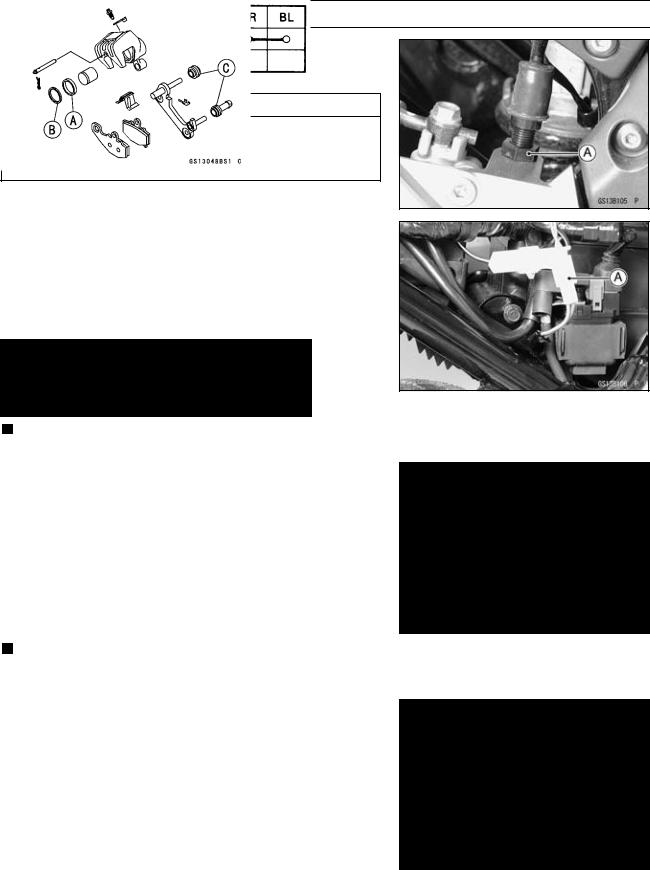
•If it does not, adjust and inspect the brake light switch. While holding the switch body, turn the adjusting nut [A] to adjust the switch.
CAUTION
To avoid damaging the electrical connections inside the switch, be sure that the switch body does not turn during adjustment.
•Remove the right side cover (see Frame chapter).
•Disconnect the connector [A].
•Using a hand tester, inspect to see that only the connection shown in the table have continuity (about zero ohms).
Special Tool - Hand Tester: 57001–1394
Rear Brake Light Switch Connections:
If the switch has an open or short, replace it with a new one.
Caliper Fluid Seal Damage
The fluid seals [A] around the piston maintain the proper pad/disc clearance. If the seals are not satisfactory, pad wear will increase, and constant pad drag on the disc will raise• brake and brake fluid temperature.
•Remove the calipers (see Brakes chapter).
Replace the fluid seals under any of the following conditions; (a) fluid leakage around the pad; (b) brakes overheat (c) there is a large difference in inner and outer pad wear; (d) the seal is stuck to the piston.
If the fluid seal is replaced, replace the dust seals [B] as well. Also, replace all seals every other time the pads are changed.
Caliper• Dust Seal/Friction Boot Damage
•Remove the calipers (see Brakes chapter).
Check that the dust seals [B] and friction boots [C] are not
•cracked, worn, swollen, or otherwise damaged.
If they show any damage, remove the caliper bracket and replace them.
PERIODIC MAINTENANCE 2-31
Periodic Maintenance Procedures
Master• Cylinder Inspection (Visual Inspection)
•Remove the master cylinders (see Brakes chapter).
•Disassemble the front and rear master cylinders.
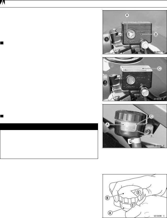
Check that there are no scratches, rust or pitting on the inner wall [A] of each master cylinder and on the outside of each piston [B].
If a master cylinder or piston shows any damage, replace
•them.
Inspect the primary cup [C] and secondary cup [D].
If a cup is worn, damaged softened (rotted), or swollen, the piston assembly should be replaced to renew the cups.
If fluid leakage is noted at the brake lever, the piston assembly should be replaced to renew the cups.
Front Master Cylinder [J]
•Check the dust covers [E] for damage.
•If they are damaged, replace them.
Check the piston return springs [F] for any damage.
•If the springs are damaged, replace them.
Check that relief port [G] and supply port [H] are not plugged.
If the relief port becomes plugged, the brake pads will drag on the disc. Blow the ports clean with compressed air.
Rear Master Cylinder [K]
PERIODIC MAINTENANCE 2-33
Periodic Maintenance Procedures
•Level the brake fluid reservoir.
•Remove the reservoir cap and diaphragm.
•Remove the rubber cap from the bleed valve [A] on the
•caliper.
Attach a clear plastic hose [B] to the bleed valve, and run
•the other end of the hose into a container.
Fill the reservoir with fresh specified brake fluid.
•Change the brake fluid:
○Repeat this operation until fresh brake fluid comes out from the plastic hose or the color of the fluid changes.
1. Open the bleed valve [A].
2. Apply the brake and hold it [B].
3. Close the bleed valve [C].
4. Release the brake [D].
NOTE
○The fluid level must be checked often during the changing operation and replenished with fresh brake fluid. If the fluid in the reservoir runs out any time during the changing operation, the brakes will need to be bled since air will have entered the brake line.
○Front Brake: Repeat the above steps for the other caliper.
○Rear Brake: Repeat the above steps for the other bleed valve.
•Remove the clear plastic hose.
•Install the reservoir cap.
•Tighten:
Torque - Front Brake Reservoir Cap Screws: 1.0 N·m (0.10 kgf·m, 9 in·lb)
•Follow procedure below to rear brake fluid reservoir cap ○correctly.First, tighten the rear brake fluid reservoir cap [B] clockwise [C] by hand until slight resistance is felt indicating that the cap is seated on the reservoir body, then tighten the cap an additional 1/6 turn [D] while holding the brake
fluid reservoir body [A].
•Tighten the bleed valve, and install the rubber cap.
•Torque - Bleed Valve: 7.8 N·m (0.80 kgf·m, 69 in·lb)
After changing the fluid, check the brake for good braking power, no brake drag, and no fluid leakage.
If necessary, bleed the air from the lines.