


FUEL SYSTEM (DFI) 3-81
Fuel Injectors
Removal/Installation•
Refer to the Throttle Body Assy Disassembly/Assembly.
Audible• Inspection
•Start the engine.
Apply the tip of a screwdriver [A] to the injector [C]. Put the grip end onto your ear, and listen whether the injector is clicking or not.
○•A sound scope [B] can also be used. Do the same for the other injectors.
If all the injectors click at a regular intervals, the injectors are good. The trouble may be related to the fuel line, requiring fuel pressure inspection (see Fuel Line section in this chapter).
○The click interval becomes shorter as the engine speed rises.
If any injector(s) doesn’t click, the DFI circuit or the injector is suspect. Perform “Power Source Voltage Inspection”, first.
Power• Source Voltage Inspection
Remove the ECU (see ECU section). Do not disconnect
•the ECU connector.
Connect a digital meter [A] to the ECU connector [B], using the needle adapter [C].
Special Tool - Needle Adapter Set: 57001–1457
Measure the power source voltage with the engine
○
•stopped, and with the connector joined. Turn the ignition switch ON.
Injector Power Source Voltage at ECU
Connections: Meter (+) → W/Y (terminal 13)
Meter (–) → Battery (–) Terminal
Service Limit: Voltage (12.6 V or more)
If the meter doesn’t read as specified, check the following.
Main Fuse 30 A (see Electrical System chapter)
Fuel Pump Relay (see DFI Power Source section)
Power Source Wiring (see Wiring Diagram below)
○To check the W/R leads between the injector connector and the fuel pump relay, remove the fuel tank (see Fuel Tank Removal) and the seat cover (see Frame chapter). If the power source voltage is normal, check the output voltage of the injectors.

3-82 FUEL SYSTEM (DFI)
Fuel Injectors
Output• Voltage Inspection
•Turn the ignition switch OFF.
•Remove the ECU (see ECU section).
Connect a digital voltmeter [A] to the ECU connector [B] with the needle adapter set [C].
Special Tool - Needle Adapter Set: 57001-1457
•Turn the ignition switch ON.
Output Voltage at Injector Connector |
|
Standard: |
Battery Voltage (12.6 V or more) |
If the output voltage is normal, perform “Injector Signal Test”.
If the output voltage is out of the standard, turn the ignition switch OFF, remove the fuel tank, and check the injector wiring for continuity.
Injector Wiring Inspection
ECU Connector Injector Connectors Terminal 36 → Injector #1 Terminal (BL/R) Terminal 35 → Injector #2 Terminal (BL/G)
Terminal 49 → Injector #3 Terminal (BL/BK) Terminal 48 → Injector #4 Terminal (BL/Y)
If the wiring is good, inspect the resistance of the injectors
•(see Injector Resistance Inspection in chapter).
•Remove the needle adapter.
Apply silicone sealant to the seals of the ECU connector for waterproofing.

FUEL SYSTEM (DFI) 3-83
Fuel Injectors
Injector• Signal Test
Prepare two test light sets with male terminals as shown.
Rating of Bulb [A]: 12 V × 3 3.4 W
Terminal Width [B]: 1.8 mm (0.071 in.)
Terminal Thickness [C]: 0.8 mm (0.031 in.)
CAUTION
Do not use larger terminals than specified above. A larger terminal could damage the injector main harness connector (female), leading to harness repair or replacement.
Be sure to connect bulbs in series. The bulb works as a current limiter to protect the solenoid in the injector from excessive current.
•Remove the fuel tank (see Fuel Tank Removal).
•Remove connectors for injector [A].
•Connect each test light set [B] to the injector sub harness
•connector [C].
•Turn the ignition switch ON.
While cranking the engine with the starter motor, watch the test lights.
If the test lights flicker at regular intervals, the injector circuit in the ECU, and the wiring are good. Perform the “Injector Resistance Inspection”.
○Injector signals can be also confirmed by connecting the hand tester (× 10 V AC) instead of the test light set to the injector main harness (female) connector. Crank the engine with the starter motor, and check to see if the hand oscillates at regular intervals.
Special Tool - Hand Tester: 57001–1394
If the test light doesn’t flicker (or the tester needle doesn’t oscillates), check the wiring and connectors again. If the wiring is good, check the injector voltage. If the wiring is good, inspect the ECU for its ground and power supply (see ECU section).

3-84 FUEL SYSTEM (DFI)
Fuel Injectors
Injector• Resistance Inspection
•Remove the fuel tank (see Fuel Tank Removal). Disconnect the connector from the injector [A] (see Throt-
•tle Body Assy Disassembly/Assembly).
Measure the injector resistance with the hand tester [B].
Special Tool - Hand Tester: 57001–1394
Injector Resistance Connections to Injector
Meter (+) Meter (–) #1: W/R ←→ BL/R Terminal #2: W/R ←→ BL/G Terminal
#3: W/R ←→ BL/BK Terminal #4: W/R ←→ BL/Y Terminal
Standard: about 11.7 12.3 Ω @20°C (68°F)
If the reading is out of the range, perform the “Injector Unit Test”.
If the reading is normal, perform the “Injector Unit Test” for confirmation.
Injector• Unit Test
Use two leads [A] and the same test light set [B] as in “Injector Signal Test”.
Rating of Bulb [C]: 12 V × (3 3.4) W
12 V Battery [D]
CAUTION
Be sure to connect the bulb in series. The bulb works as a current limiter to protect the solenoid in the injector from excessive current.
•Connect the test light set to the injector [E] as shown.
•Open and connect [F] the end of the lead to the battery
(–) terminal repeatedly. The injector should click. If the injector does not click, replace the injector.
If the injector clicks, check the wiring again. If the wiring is good, replace the injector (may be clogged) or ECU.
Injector• Fuel Line Inspection
While pinching the fuel pump outlet hose joint locks [A] with fingers, pull the joint out along the delivery pipe (see Fuel Tank Removal).
Cloth [B]
Pump Outlet Hose Joint [C]
FUEL SYSTEM (DFI) 3-85
Fuel Injectors
•Check the injector fuel line for leakage as follows: ○Connect a commercially available vacuum/pressure
pump [A] to the nipple of the delivery pipe [B] with a high-pressure fuel hose [C] (both ends connected with the clamps [D]) as shown.
Torque - Fuel Hose Clamp Screws: 1.5 N·m (0.15 kgf·m, 13 in·lb)
○Apply soap and water solution to the areas [E] as shown. ○Watching the pressure gauge, squeeze the pump lever [F], and build up the pressure until the pressure reaches
the maximum pressure.
Injector Fuel Line Maximum Pressure Standard: 300 kPa (3.06 kgf/cm², 43 psi)
CAUTION
During pressure testing, do not exceed the maximum pressure for which the system is designed.
•Watch the gauge for at least 6 seconds.
If the pressure holds steady, the system is good.
If the pressure drops at once or if bubbles are found in the area, the line is leaking. Replace the delivery pipe, injectors and related parts.
○Repeat the leak test, and check the fuel line for no leak-
•age.
•Install the pump outlet hose (see Fuel Tank Installation). Run the hoses correctly (see Cable, Wire, and Hose Routing section in Appendix chapter).
3-86 FUEL SYSTEM (DFI)
Fuel Injectors
|
|
|
|
|
|
|
|
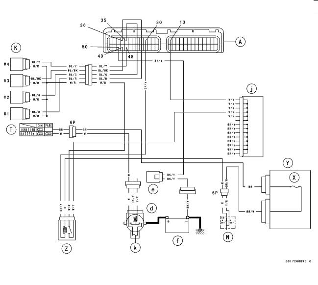
A. ECU |
Y. Junction Box |
f. Sealed Battery |
|
K. Fuel Injectors |
Z. Fuel Pump Relay (for fuel |
j. Joint Connector B |
|
N. Engine Stop Switch |
pump an injectors) |
k. Main Fuse 30 A |
|
T. Ignition Switch |
d. Starter Relay |
|
|
X. Ignition Fuse 10 A |
e. Joint Connector C |
|
|