

3) Installation of the Auxiliary Machinery:
All shipyards are equipped with powerful cranes for shipbuilding by the large prefabricated section method is a fact in favour of the introduction of integrated methods of installing mechanical equipment, for plant of practically any weight can be handled.
According to the method by which it is installed, the auxiliary machinery can be subdivided into four categories:
1) machinery supplied to the ship in the form of individual complete assemblies; these have to be aligned on the ship and fixed to the foundations on wedges (for instance, the steering machinery);
2) machinery including power and working units in the same housing (for instance, turbine and electric pumps);
3) machinery mounted on one foundation frame by means of which it is connected to the ship's foundations (diesel generators, diesel compressors, etc.);
4) machinery with no moving parts (ejector pumps, filters, evaporators, desalination plant, condensers, etc.).
Before the auxiliary machinery is installed a check is carried out to ensure that the foundation for the machinery is correctly positioned relative to the base planes and that the dimensions of the supporting surfaces correspond to those shown on the drawings.
The supporting surfaces of the foundations for machinery in the first and second categories are machined using portable (pneumatic) grinders or milling machines, and are filed to a checking template in the same way as the foundations for shaft-line bearings or the main propulsive machinery. Machinery in the first category is aligned by straight edge and feeler gauge, or by indicators, and then mounted on steel wedges or spherical spacing pieces. Machinery in the second category is installed without wedges directly on the machined supporting surface of the foundation, to which it is bolted. If the drawings prescribe that the machinery must be in some particular position relative to the supporting surface of its foundation, machinery is mounted on steel spacing pieces of the required thickness.
M
The shock absorbers are first fixed to the foundation, and the machinery then mounted on them. The bolts are taken up until the base or frame of the machinery makes complete contact with the upper ends of the shock absorber sleeves (or spacing washers), and they are then taken up a further half turn.
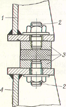
Plate shock absorbers are also used; these consist of steel plates which a layer of rubber is vulcanized. They are fixed to the
Pic. 32. Installation on plate shock absorbers: 1) machinery frame; 2) studs; 3)plate shock absorber; 4) foundation
foundation and machinery with studs which do not reach the layer of rubber. These shock absorbers are not always sufficiently reliable.