

Text 6b
HULL WORKS
PART I: GENERAL OUTLINE OF HULL CONSTRUCTION
In any kind of vessel the principal problem is the hull construction corresponding to strength and rigidity requirements. The hull of going vessel must withstand water pressure tending to collapse it from sides, while the heavy masses of cargo together act from inside. These cargo masses with the hull weight directed vertically downwards tend to immerse the hull into water, while water sustaining forces directed vertically upwards tend to force it up. Thus being subjected to the diametrically opposite forces the hull tends to bend longitudinally: in addition stresses caused at rolling display tendency to transverse section deformation.
When grounding or resting in dry deck the hull is subjected to new stresses from machinery and engine room operation. Thus the principal stresses to which the hull of a vessel is subjected depend on the longitudinal bending of the hull overall, its transverse deformation and various stresses acting in different parts of a vessel. The hull construction therefore must be strong and rigid enough to withstand all indicated stresses.
The hull is subdivided into the following main parts:
-
Hull.
-
Superstructures.
-
Subdivision members (compartments, castings).
Let us examine the main parts of the hull.
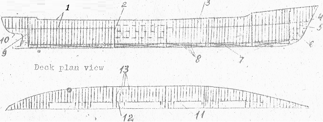
Pic. 26. General arrangement of framing
1. Deck; 2. Transverse bulkhead; 3. Side frame; 4. Stem; 5. Forepeak; 6. Side stringer; 7. Double bottom; 8. Floor; 9. Afterpeak; 10. Sternpost; 11. Hatch; 12. Carling; 13. Deck beam
Properly the hull consists of the framing and shell. The shell is subdivided into a bottom shell, side shell and deck plating. The framing and the shell are the main structural members of the hull. They include the following members:
-
bottom framing and shell;
-
side framing and shell;
-
deck framing and deck plating.
Typical superstructures are:
-
The forecastle in the forward part of the ship which begins from stem;
-
The bridge is located amidships. The designation of the bridge is to protect the ship from getting water through openings in the machine and other castings.
-
The poop is a superstructure in the aft to protect the rudder arrangement and to cover the machine and boiler castings if they are arranged in the stern.
The space between all these superstructures of the upper deck is usually protected by with bulwarks.
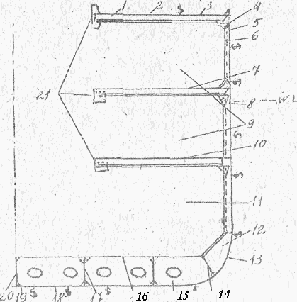
Pic.27. Section of dry cargo ship
1. Deck Beam; 2. Upper deck plating; 3. Deck stringer; 4. Beam knee; 5. Sheer strake; 6. Frame; 7. Second deck plating; 8. Ice strake; 9. Tweendeck; 10. Third deck plating; 11. Hold; 12. Bilge bracket; 13. Bilge strake; 14. Margin plate; 15. Floor; 16. Tank top; 17. Keelson; 18. Garboard strake; 19. Flat plate keel; 20. Vertical keel; 21. Side hatch coaming
Subdivision members of the ship serve to provide unsinking of the ship, fire- proof safety and the strength of the ship. Subdivision members are accomplished with the arrangement of decks and partial decks and with the arrangement of transverse and longitudinal bulkheads. They make compartments of the two kinds: decks of the hull and decks of the superstructures. Decks of the hull are as follows: (1) upper deck, (2) middle deck, (3) lower deck and (4) platform.
The decks of superstructure are the following: (1) bridge deck, (2) lower promenade deck, (3) upper promenade deck and (4) boat deck.
Taking into consideration all this the hull construction of a modern vessel is composed of (1) longitudinal framework, keel, keelsons, stringers, deck girders, longitudinal bulkheads, hull and deck plating; and (2) transverse framework, beams, transverse bulkheads, wooden deck, etc. As for the external shell plating and deck plating they also stiffen the hull transversely. At interconnections of longitudinals and transversals additional ties are introduced such as in the form of brackets and straps.

Pic. 28. Transverse bulkhead:
1 – stiffener; 2 – shelf plate
Rigidity stability and permanent depth of hull is guaranteed by floors, side plating longitudinal and transverse bulkheads as well as by pillars. Local rigidity at the ends of the hull is also secured by stem and stern.
PART II: SELECTION OF METHODS OF HULL SHAPING
-
Pyramid method of building up hulls from prefabricated sections.
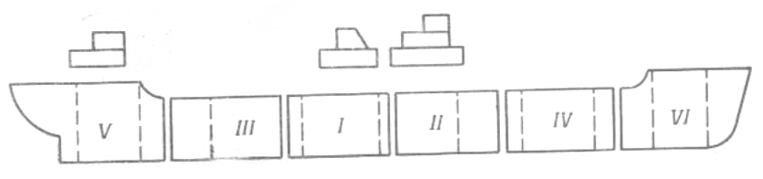
When the pyramid method is used, building up the hull on the building berth starts with the assembly and welding of the first pyramid, with the sections in the subsequent pyramids butt-assembled to it. The entire hull is assembled and welded successively forward and astern from the centre of the prefabricated bottom section of the first pyramid, and to the sides and upwards; this ensures that there is free contraction while welding sections, and consequently reduces the total hull deformations. When the first pyramid has been assembled and welded, although it is comparatively short, its section relative to the horizontal axis is already sufficiently rigid.

Pic. 29. Pyramid method: I-V11—pyramid Nos.; the sections for pyramids I, III, V and VII are shaded
This method gives the hull its initial shape as to transverse cross-section (in breadth and depth), but formation in length is somewhat retarded; extension of the working front in the first stage of assembly on the building berth is thus limited.
This method has been given the name "pyramid" since seen from the side the assembled part of the hull represents a pyramid with the terraces formed by the outlines of the individual sections. When the first pyramid has been completely welded, the sections forming the next pyramids are assembled and welded simultaneously, and the fitting-out and installation work is at the same time done in the finished sections of the first pyramid. With the completion of welding on each successive pyramid, fitting-out and installation operations are carried out on an increasingly wide front.
-
The "island" method of building up the hull froт sections.
The working front can be further extended by using the "island" method of assembly; when this method is used, sections are simultaneously placed in position at two or three zones along the hull (for instance, at the midship, bow, and stern zones). In many cases the sequence of assembly and welding within each island may be the same as with the pyramid method. As soon as welding is finished in each island, fitting-out and installation operations are begun.

Pic. 30. The “island” method: А, В and С—the stern, midship and bow islands; the sections for the initial pyramids in each island arc shown by the criss-cross shading
There may be two, three or more islands, depending on the type, size and design of the ship, also on a number of other factors. The difficulty of building a hull by this method lies in joining the islands together. If the islands are assembled on movable trolleys, they can be joined together by moving the trolleys. If the islands are assembled on keelblocks, connecting sections should be installed along the entire perimeter of the hull to join the islands together.
-
The block method of hull construction.
When hulls are constructed by the block method, the building berth assembly cycle is reduced to a minimum, and the welding deformations are also minimum. In the block method the "blocks" (completed parts of the hull
Pic. 31. The block method: I-VI – hull blocks Nos., in the sequence of installing
between sections parallel to the midship plane) are assembled from previously fabricated sections in which installation work has already been done. The finished blocks are despatched lo the building berth, where they are butt-assembled; the installation work in the regions of the butt joints is then completed.
The first block to be placed into position is the base block( in the centre) ; when its position has been checked and it has been fixed on the building berth the neighbouring blocks are joined to it, either one at a time or both at once. If there are a large number of blocks it is sometimes effective to join them in groups of two or three, and then to join two groups (symmetrically) to the base group.
Ex. 12. Revise the terms from your active vocabulary.
a) Using the definitions, rearrange the letters to find words used in the text:
PGITANL 1. the hull’s shell;
ASTRELEFOC 2. the superstructure erected at the forward end
of the ship;
BEGIRD 3. the superstructure erected about amidships;
WARBULK 4. the strake of shell plating which serves as a
quard against losing deck cargo or men
overboard;
LAKDEHUBS 5. the vertical watertight partitions;
SOFORL 6. the transverse girders stiffening the bottom
plating;
RINGMAF 7. the girderwork stiffening the hull;
RESTGIRNS 8. the longitudinal girders stiffening the side
plating;
ONESKLES 9. the longitudinal girders stiffening the bot-
tom plating;
STOPNREST 10. the rigid structure at the stern.
b) Match the words with their definitions:
The forward end of the hull longitudinal bulkheads
The after end of the hull the bottom
The lowermost part of the hull the poop
The topping part of the hull the stern
The wall of the hull side frames
The hull’s shell the forepeak
The superstructure erected at the
after end of the ship side stringers
The transverse girders stiffening the plating
the side plating
The longitudinal girders stiffening
the side plating the deck
The foremost compartment a side
The bulkheads erected fore the bow
and aft
Ex. 13. Match the pairs of