

usb_2.0_english
.pdfUniversal Serial Bus Specification Revision 2.0
5.8.3 Bulk Transfer Packet Size Constraints
An endpoint for bulk transfers specifies the maximum data payload size that the endpoint can accept from or transmit to the bus. The USB defines the allowable maximum bulk data payload sizes to be only 8, 16, 32, or 64 bytes for full-speed endpoints and 512 bytes for high-speed endpoints. A low-speed device must not have bulk endpoints. This maximum applies to the data payloads of the data packets; i.e., the size specified is for the data field of the packet as defined in Chapter 8, not including other protocol-required information.
A bulk endpoint is designed to support a maximum data payload size. A bulk endpoint reports in its configuration information the value for its maximum data payload size. The USB does not require that data payloads transmitted be exactly the maximum size; i.e., if a data payload is less than the maximum, it does not need to be padded to the maximum size.
All Host Controllers are required to have support for 8-, 16-, 32-, and 64-byte maximum packet sizes for full-speed bulk endpoints and 512 bytes for high-speed bulk endpoints. No Host Controller is required to support larger or smaller maximum packet sizes.
During configuration, the USB System Software reads the endpoint’s maximum data payload size and ensures that no data payload will be sent to the endpoint that is larger than the supported size.
An endpoint must always transmit data payloads with a data field less than or equal to the endpoint’s reported wMaxPacketSize value. When a bulk IRP involves more data than can fit in one maximum-sized data payload, all data payloads are required to be maximum size except for the last data payload, which will contain the remaining data. A bulk transfer is complete when the endpoint does one of the following:
•Has transferred exactly the amount of data expected
•Transfers a packet with a payload size less than wMaxPacketSize or transfers a zero-length packet
When a bulk transfer is complete, the Host Controller retires the current IRP and advances to the next IRP. If a data payload is received that is larger than expected, all pending bulk IRPs for that endpoint will be aborted/retired.
5.8.4 Bulk Transfer Bus Access Constraints
Only full-speed and high-speed devices can use bulk transfers.
An endpoint has no way to indicate a desired bus access frequency for a bulk pipe. The USB balances the bus access requirements of all bulk pipes and the specific IRPs that are pending to provide “good effort” delivery of data between client software and functions. Moving control transfers over the bus has priority over moving bulk transfers.
There is no time guaranteed to be available for bulk transfers as there is for control transfers. Bulk transfers are moved over the bus only on a bandwidth-available basis. If there is bus time that is not being used for other purposes, bulk transfers will be moved over the bus. If there are bulk transfers pending for multiple endpoints, bulk transfers for the different endpoints are selected according to a fair access policy that is Host Controller implementation-dependent.
All bulk transfers pending in a system contend for the same available bus time. Because of this, the USB System Software at its discretion can vary the bus time made available for bulk transfers to a particular endpoint. An endpoint and its client software cannot assume a specific rate of service for bulk transfers. Bus time made available to a software client and its endpoint can be changed as other devices are inserted into and removed from the system or also as bulk transfers are requested for other device endpoints. Client software cannot assume ordering between bulk and control transfers; i.e., in some situations, bulk transfers can be delivered ahead of control transfers.
High-speed bulk OUT endpoints must support the PING flow control protocol. The details of this protocol are described in Section 8.5.1.
53

Universal Serial Bus Specification Revision 2.0
The bus frequency and (micro)frame timing limit the maximum number of successful bulk transactions within a (micro)frame for any USB system to less than 72 full-speed eight-byte data payloads or less than 14 high-speed 512-byte data payloads. Table 5-9 lists information about different-sized full-speed bulk transactions and the maximum number of transactions possible in a frame. The table does not include the overhead associated with bit stuffing. Table 5-10 lists similar information for high-speed bulk transactions.
Table 5-9. Full-speed Bulk Transaction Limits
Protocol Overhead (13 bytes) (3 SYNC bytes, 3 PID bytes, 2 Endpoint + CRC bytes, 2 CRC bytes, and a 3-byte interpacket delay)
|
|
|
|
|
|
|
|
|
|
|
|
|
|
|
|
|
|
|
|
|
Data |
|
|
Max Bandwidth |
|
Frame |
|
Max |
|
Bytes |
|
|
Bytes/Frame |
|
|
|
|
Payload |
|
|
(bytes/second) |
|
Bandwidth |
|
Transfers |
|
Remaining |
|
|
Useful Data |
|
|
|
|
|
|
|
|
|
per Transfer |
|
|
|
|
|
|
|
|
|
|
|
|
|
|
|
|
|
|
|
|||||
|
|
|
1 |
107000 |
1% |
107 |
2 |
107 |
||||||||
|
|
|
|
|
|
|
|
|
||||||||
|
|
|
2 |
200000 |
1% |
100 |
0 |
200 |
||||||||
|
|
|
|
|
|
|
|
|
||||||||
|
|
|
4 |
352000 |
1% |
88 |
4 |
352 |
||||||||
|
|
|
|
|
|
|
|
|
||||||||
|
|
|
8 |
568000 |
1% |
71 |
9 |
568 |
||||||||
|
|
|
|
|
|
|
|
|
||||||||
|
|
|
16 |
816000 |
2% |
51 |
21 |
816 |
||||||||
|
|
|
|
|
|
|
|
|
||||||||
|
|
|
32 |
1056000 |
3% |
33 |
15 |
1056 |
||||||||
|
|
|
|
|
|
|
|
|
||||||||
|
|
|
64 |
1216000 |
5% |
19 |
37 |
1216 |
||||||||
|
|
|
|
|
|
|
|
|
|
|
|
|
|
|
||
|
Max |
|
1500000 |
|
|
|
|
|
|
1500 |
||||||
|
|
|
|
|
|
|
|
|
|
|
|
|
|
|
|
|
54

Universal Serial Bus Specification Revision 2.0
Table 5-10. High-speed Bulk Transaction Limits
Protocol Overhead (55 bytes) (3x4 SYNC bytes, 3 PID bytes, 2 EP/ADDR+CRC bytes,
2 CRC16, and a 3x(1+11) byte interpacket delay (EOP, etc.))
|
|
|
|
|
|
|
|
|
|
|
|
|
|
|
|
|
|
|
|
|
Data |
|
|
Max Bandwidth |
|
Microframe |
|
Max |
|
Bytes |
|
|
Bytes/ |
|
|
|
|
Payload |
|
|
(bytes/second) |
|
Bandwidth |
|
Transfers |
|
Remaining |
|
|
Microframe |
|
|
|
|
|
|
|
|
|
per Transfer |
|
|
|
|
|
|
Useful Data |
|
|
|
|
|
|
|
|
|
|
|
|
|||||
|
|
|
1 |
1064000 |
1% |
133 |
52 |
133 |
||||||||
|
|
|
|
|
|
|
|
|
||||||||
|
|
|
2 |
2096000 |
1% |
131 |
33 |
262 |
||||||||
|
|
|
|
|
|
|
|
|
||||||||
|
|
|
4 |
4064000 |
1% |
127 |
7 |
508 |
||||||||
|
|
|
|
|
|
|
|
|
||||||||
|
|
|
8 |
7616000 |
1% |
119 |
3 |
952 |
||||||||
|
|
|
|
|
|
|
|
|
||||||||
|
|
|
16 |
13440000 |
1% |
105 |
45 |
1680 |
||||||||
|
|
|
|
|
|
|
|
|
||||||||
|
|
|
32 |
22016000 |
1% |
86 |
18 |
2752 |
||||||||
|
|
|
|
|
|
|
|
|
||||||||
|
|
|
64 |
32256000 |
2% |
63 |
3 |
4032 |
||||||||
|
|
|
|
|
|
|
|
|
||||||||
|
|
|
128 |
40960000 |
2% |
40 |
180 |
5120 |
||||||||
|
|
|
|
|
|
|
|
|
||||||||
|
|
|
256 |
49152000 |
4% |
24 |
36 |
6144 |
||||||||
|
|
|
|
|
|
|
|
|
||||||||
|
|
|
512 |
53248000 |
8% |
13 |
129 |
6656 |
||||||||
|
|
|
|
|
|
|
|
|
|
|
|
|
|
|
||
|
Max |
|
60000000 |
|
|
|
|
|
|
7500 |
||||||
|
|
|
|
|
|
|
|
|
|
|
|
|
|
|
|
|
Host Controllers are free to determine how the individual bus transactions for specific bulk transfers are moved over the bus within and across (micro)frames. An endpoint could see all bus transactions for a bulk transfer within the same (micro)frame or spread across several (micro)frames. A Host Controller, for various implementation reasons, may not be able to provide the above maximum number of transactions per (micro)frame.
5.8.5 Bulk Transfer Data Sequences
Bulk transactions use data toggle bits that are toggled only upon successful transaction completion to preserve synchronization between transmitter and receiver when transactions are retried due to errors. Bulk transactions are initialized to DATA0 when the endpoint is configured by an appropriate control transfer. The host will also start the first bulk transaction with DATA0. If a halt condition is detected on a bulk pipe due to transmission errors or a STALL handshake being returned from the endpoint, all pending IRPs are retired. Removal of the halt condition is achieved via software intervention through a separate control pipe. This recovery will reset the data toggle bit to DATA0 for the endpoint on both the host and the device.
Bulk transactions are retried due to errors detected on the bus that affect a given transaction.
55

Universal Serial Bus Specification Revision 2.0
5.9 High-Speed, High Bandwidth Endpoints
USB supports individual high-speed interrupt or isochronous endpoints that require data rates up to
192 Mb/s (i.e., 3072 data bytes per microframe). One, two, or three high-speed transactions are allowed in a single microframe to support high-bandwidth endpoints.
A high-speed interrupt or isochronous endpoint indicates that it requires more than 1024 bytes per microframe when bits 12..11 of the wMaxPacketSize field of the endpoint descriptor (see Table 5-11) are non-zero. The lower 11 bits of wMaxPacketSize indicate the size of the data payload for each individual transaction while bits 12..11 indicate the maximum number of required transactions possible. See Section 9.6.6 for restrictions on the allowed combinations of values for bits 12..11 and bits 10..0.
Table 5-11. wMaxPacketSize Field of Endpoint Descriptor
Bits |
15..13 |
12..11 |
10..0 |
|
|
|
|
Field |
Reserved, |
Number of transactions |
Maximum size of data |
|
must be |
per microframe |
payload in bytes |
|
set to zero |
|
|
|
|
|
|
Note: This representation means that endpoints requesting two transactions per microframe will specify a total data payload size in the microframe that is a multiple of two bytes. Also endpoints requesting three transactions per microframe will specify a total data payload size that is a multiple of three bytes. In any case, any number of bytes can actually be transferred in a microframe.
The host controller must issue an appropriate number of high-speed transactions per microframe. Errors in the host or on the bus can result in the host controller issuing fewer transactions than requested for the endpoint. The first transaction(s) must have a data payload(s) as specified by the lower 11 bits of wMaxPacketSize if enough data is available, while the last transaction has any remaining data less than or equal to the maximum size specified. The host controller may issue transactions for the same endpoint one immediately after the other (as required for the actual data provided) or may issue transactions for other endpoints in between the transactions for a high bandwidth endpoint.
5.9.1 High Bandwidth Interrupt Endpoints
For interrupt transactions, if the endpoint NAKs a transaction during a microframe, the host controller must not issue further transactions for that endpoint until the next period.
If the endpoint times-out a transaction, the host controller must retry the transaction. The endpoint specifies the maximum number of desired transactions per microframe. If the maximum number of transactions per microframe has not been reached, the host controller may immediately retry the transaction during the current microframe. Host controllers are recommended to do an immediate retry since this minimizes impact on devices that are bandwidth sensitive. If the maximum number of transactions per microframe has been reached, the host controller must retry the transaction at the next period for the endpoint.
A host controller is allowed to issue less than the maximum number of transactions to an endpoint per microframe only if more than a single memory buffer is required for the transactions within the microframe.
Normal DATA0/DATA1 data toggle sequencing is used for each interrupt transaction during a microframe.
56
Universal Serial Bus Specification Revision 2.0
5.9.2 High Bandwidth Isochronous Endpoints
For isochronous transactions, if an IN endpoint provides less than a maximum data payload as specified by its endpoint descriptor, the host must not issue further transactions for that endpoint for that microframe.
For an isochronous OUT endpoint, the host controller must issue the number of transactions as required for the actual data provided, not exceeding the maximum number specified by the endpoint descriptor. The transactions issued must adhere to the maximum payload sizes as specified in the endpoint descriptor.
No retries are ever done for isochronous endpoints.
High bandwidth isochronous endpoints (IN and OUT) must support data PID sequencing. Data PID sequencing provides the required support for the data receiver to detect one or more lost/damaged packets per microframe.
Data PID sequencing for a high-speed, high bandwidth isochronous IN endpoint uses a repeating sequence of DATA2, DATA1, DATA0 PIDs for the data packet of each transaction in a microframe. If there is only a single transaction in the microframe, only a DATA0 data packet PID is used. If there are two transactions per microframe, DATA1 is used for the first transaction data packet and DATA0 is used for the second transaction data packet. If there are three transactions per microframe, DATA2 is used for the first transaction data packet, DATA1 is used for the second, and DATA0 is used for the third. In all cases, the data PID sequence starts over again the next microframe. Figure 5-11 shows the order of data packet PIDs that are used in subsequent transactions within a microframe for high-bandwidth isochronous IN endpoints.
1 transaction, <1024 bytes: |
DATA0 |
|
|
|
|
|
|
|
|
|
|
2 transactions, 513-1024 bytes ea.: |
DATA1 |
|
DATA0 |
|
|
|
|
|
|
|
|
3 transactions, 683-1024 bytes ea.: |
DATA2 |
|
DATA1 |
|
DATA0 |
|
|
|
|
|
|
Figure 5-11. Data Phase PID Sequence for Isochronous IN High Bandwidth Endpoints
An endpoint must respond to an IN token for the first transaction with a DATA2 when it requires three transactions of data to be moved. It must respond with a DATA1 for the first transaction when it requires two transactions and with a DATA0 when it requires only a single transaction. After the first transaction, the endpoint follows the data PID sequence as described above.
The host knows the maximum number of allowed transactions per microframe for the IN endpoint. The host expects the response to the first transaction to encode (via the data packet PID) how many transactions are required by the endpoint for this microframe. If the host doesn’t receive an error-free, appropriate response to any transaction, the host must not issue any further transactions to the endpoint for that microframe. When the host receives a DATA0 data packet from the endpoint, it must not issue any further transactions to the endpoint for that microframe.
Data PID sequencing for a high-speed, high bandwidth isochronous OUT endpoint uses a different sequence than that used for an IN endpoint. The host must issue a DATA0 data packet when there is a single transaction. The host must issue an MDATA for the first transaction and a DATA1 for the second transaction when there are two transactions per microframe. The host must issue two MDATA transactions and a DATA2 for the third transaction when there are three transactions per microframe. These sequences allow the endpoint to detect if there was a lost/damaged transaction during a microframe. Figure 5-12 shows the order of data packet PIDs that are used in subsequent transactions within a microframe for highbandwidth isochronous OUT.
57
Universal Serial Bus Specification Revision 2.0
1 transaction, <1024 bytes: |
DATA0 |
|
|
|
|
|
|
|
|
|
|
2 transactions, 513-1024 bytes ea.: |
MDATA |
|
DATA1 |
|
|
|
|
|
|
|
|
3 transactions, 683-1024 bytes ea.: |
MDATA |
|
MDATA |
|
DATA2 |
|
|
|
|
|
|
Figure 5-12. Data Phase PID Sequence for Isochronous OUT High Bandwidth Endpoints
If the wrong OUT transactions are detected by the endpoint, all of the data transferred during the microframe must be treated as if it had encountered an error. Note that for the three transactions per microframe case with a missing MDATA transaction, USB provides no way for the endpoint to determine which of the two MDATA transactions was lost. There may be application specific methods to more precisely determine which data was lost, but USB provides no method to do so at the bus level.
5.10 Split Transactions
Host controllers and hubs support one additional transaction type called split transactions. This transaction type allows fulland low-speed devices to be attached to hubs operating at high-speed. These transactions involve only host controllers and hubs and are not visible to devices. High-speed split transactions for interrupt and isochronous transfers must be allocated by the host from the 80% periodic portion of a microframe. More information on split transactions can be found in Chapter 8 and Chapter 11.
5.11 Bus Access for Transfers
Accomplishing any data transfer between the host and a USB device requires some use of the USB bandwidth. Supporting a wide variety of isochronous and asynchronous devices requires that each device’s transfer requirements are accommodated. The process of assigning bus bandwidth to devices is called transfer management. There are several entities on the host that coordinate the information flowing over the USB: client software, the USB Driver (USBD), and the Host Controller Driver (HCD). Implementers of these entities need to know the key concepts related to bus access:
•Transfer Management: The entities and the objects that support communication flow over the USB
•Transaction Tracking: The USB mechanisms that are used to track transactions as they move through the USB system
•Bus Time: The time it takes to move a packet of information over the bus
•Device/Software Buffer Size: The space required to support a bus transaction
•Bus Bandwidth Reclamation: Conditions where bandwidth that was allocated to other transfers but was not used and can now be possibly reused by control and bulk transfers
The previous sections focused on how client software relates to a function and what the logical flows are over a pipe between the two entities. This section focuses on the different parts of the host and how they must interact to support moving data over the USB. This information may also be of interest to device implementers so they understand aspects of what the host is doing when a client requests a transfer and how that transfer is presented to the device.
58
Universal Serial Bus Specification Revision 2.0
5.11.1 Transfer Management
Transfer management involves several entities that operate on different objects in order to move transactions over the bus:
•Client Software: Consumes/generates function-specific data to/from a function endpoint via calls and callbacks requesting IRPs with the USBD interface.
•USB Driver (USBD): Converts data in client IRPs to/from device endpoint via calls/callbacks with the appropriate HCD. A single client IRP may involve one or more transfers.
•Host Controller Driver (HCD): Converts IRPs to/from transactions (as required by a Host Controller implementation) and organizes them for manipulation by the Host Controller. Interactions between the HCD and its hardware is implementation-dependent and is outside the scope of the USB Specification.
•Host Controller: Takes transactions and generates bus activity via packets to move function-specific data across the bus for each transaction.
Figure 5-13 shows how the entities are organized as information flows between client software and the USB. The objects of primary interest to each entity are shown at the interfaces between entities.
Client Software |
Data |
|
USBD
Interface
IRPs
USBD
HCD
Interface
HCD
Transfers
|
|
|
|
|
|
|
|
|
Transaction |
|
|
|
|
|
|
|
|
|
|
|
|
|
HW/SW |
|
Transaction List |
|
Transactions |
||||
|
|
|
Transaction |
|
|
|
Interface |
|
|
|
|
|
|
|
|
|
|
|
|
|
|
|
|
|
|
|
|
|
|
|
|
Host Controller
Packets
USB
Figure 5-13. USB Information Conversion From Client Software to Bus
59
Universal Serial Bus Specification Revision 2.0
5.11.1.1 Client Software
Client software determines what transfers need to be made with a function. It uses appropriate operating system-specific interfaces to request IRPs. Client software is aware only of the set of pipes (i.e., the interface) it needs to manipulate its function. The client is aware of and adheres to all bus access and bandwidth constraints as described previously for each transfer type. The requests made by the client software are presented via the USBD interface.
Some clients may manipulate USB functions via other device class interfaces defined by the operating system and may themselves not make direct USBD calls. However, there is always some lowest level client that makes USBD calls to pass IRPs to the USBD. All IRPs presented are required to adhere to the prenegotiated bandwidth constraints set when the pipe was established. If a function is moved from a nonUSB environment to the USB, the driver that would have directly manipulated the function hardware via memory or I/O accesses is the lowest client software in the USB environment that now interacts with the USBD to manipulate the driver’s USB function.
After client software has requested a transfer of its function and the request has been serviced, the client software receives notification of the completion status of the IRP. If the transfer involved function-to-host data transfer, the client software can access the data in the data buffer associated with the completed IRP.
The USBD interface is defined in Chapter 10.
5.11.1.2 USB Driver
The Universal Serial Bus Driver (USBD) is involved in mediating bus access at two general times:
•While a device is attached to the bus during configuration
•During normal transfers
When a device is attached and configured, the USBD is involved to ensure that the desired device configuration can be accommodated on the bus. The USBD receives configuration requests from the configuring software that describe the desired device configuration: endpoint(s), transfer type(s), transfer period(s), data size(s), etc. The USBD either accepts or rejects a configuration request based on bandwidth availability and the ability to accommodate that request type on the bus. If it accepts the request, the USBD creates a pipe for the requester of the desired type and with appropriate constraints as defined for the transfer type. Bandwidth allocation for periodic endpoints does not have to be made when the device is configured and, once made, a bandwidth allocation can be released without changing the device configuration.
The configuration aspects of the USBD are typically operating system-specific and heavily leverage the configuration features of the operating system to avoid defining additional (redundant) interfaces.
Once a device is configured, the software client can request IRPs to move data between it and its function endpoints.
5.11.1.3 Host Controller Driver
The Host Controller Driver (HCD) is responsible for tracking the IRPs in progress and ensuring that USB bandwidth and (micro)frame time maximums are never exceeded. When IRPs are made for a pipe, the HCD adds them to the transaction list. When an IRP is complete, the HCD notifies the requesting software client of the completion status for the IRP. If the IRP involved data transfer from the function to the software client, the data was placed in the client-indicated data buffer.
IRPs are defined in an operating system-dependent manner.
60
Universal Serial Bus Specification Revision 2.0
5.11.1.4 Transaction List
The transaction list is a Host Controller implementation-dependent description of the current outstanding set of bus transactions that need to be run on the bus. Only the HCD and its Host Controller have access to the specific representation. Each description contains transaction descriptions in which parameters, such as data size in bytes, the device address and endpoint number, and the memory area to which data is to be sent or received, are identified.
A transaction list and the interface between the HCD and its Host Controller is typically represented in an implementation-dependent fashion and is not defined explicitly as part of the USB Specification.
5.11.1.5 Host Controller
The Host Controller has access to the transaction list and translates it into bus activity. In addition, the Host Controller provides a reporting mechanism whereby the status of a transaction (done, pending, halted, etc.) can be obtained. The Host Controller converts transactions into appropriate implementation-dependent activities that result in USB packets moving over the bus topology rooted in the root hub.
The Host Controller ensures that the bus access rules defined by the protocol are obeyed, such as inter-packet timings, timeouts, babble, etc. The HCD interface provides a way for the Host Controller to participate in deciding whether a new pipe is allowed access to the bus. This is done because Host Controller implementations can have restrictions/constraints on the minimum inter-transaction times they may support for combinations of bus transactions.
The interface between the transaction list and the Host Controller is hidden within an HCD and Host Controller implementation.
5.11.2 Transaction Tracking
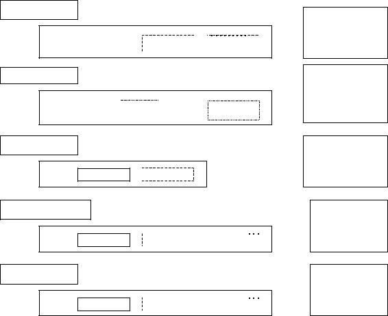
A USB function sees data flowing across the bus in packets as described in Chapter 8. The Host Controller uses some implementation-dependent representation to track what packets to transfer to/from what endpoints at what time or in what order. Most client software does not want to deal with packetized communication flows because this involves a degree of complexity and interconnect dependency that limits the implementation. The USB System Software (USBD and HCD) provides support for matching data movement requirements of a client to packets on the bus. The Host Controller hardware and software uses IRPs to track information about one or more transactions that combine to deliver a transfer of information between the client software and the function. Figure 5-14 summarizes how transactions are organized into IRPs for the four transfer types. Detailed protocol information for each transfer type can be found in Chapter 8. More information about client software views of IRPs can be found in Chapter 10 and in the operating system specific-information for a particular operating system.
61
Universal Serial Bus Specification Revision 2.0
Data Flow Types
IRP
Transaction |
|
Transaction |
|
Transaction |
|
|
|
|
|
Control Transfer
IRP
Setup |
Data |
Status |
Additional |
Transaction |
Transaction |
Transaction |
Control Transfers |
Interrupt Transfer
IRP
Transaction |
Transaction |
Isochronous Transfer
IRP
Transaction |
Transaction |
Transaction |
All transfers are composed of one or more transactions. An IRP corresponds to one or more transfers.
A control transfer is an OUT Setup transaction followed by multiple IN or OUT Data transactions followed by one “opposite of data direction” Status transaction.
An interrupt transfer is one or more IN / OUT Data transactions.
An isochronous transfer is one or more IN / OUT Data transactions.
Bulk Transfer
IRP
Transaction |
Transaction |
Transaction |
A bulk transfer is one or more IN / OUT Data transactions.
Figure 5-14. Transfers for Communication Flows
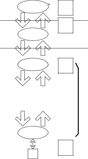
Even though IRPs track the bus transactions that need to occur to move a specific data flow over the USB, Host Controllers are free to choose how the particular bus transactions are moved over the bus subject to the USB-defined constraints (e.g., exactly one transaction per (micro)frame for isochronous transfers). In any case, an endpoint will see transactions in the order they appear within an IRP unless errors occur. For example, Figure 5-15 shows two IRPs, one each for two pipes where each IRP contains three transactions. For any transfer type, a Host Controller is free to move the first transaction of the first IRP followed by the first transaction of the second IRP somewhere in (micro)Frame 1, while moving the second transaction of each IRP in opposite order somewhere in (micro)Frame 2. If these are isochronous transfer types, that is the only degree of freedom a Host Controller has. If these are control or bulk transfers, a Host Controller could further move more or less transactions from either IRP within either (micro)frame. Functions cannot depend on seeing transactions within an IRP back-to-back within a (micro)frame nor should they depend on not seeing transactions back-to-back within a (micro)frame.
62