

usb_2.0_english
.pdfUniversal Serial Bus Specification Revision 2.0
|
|
|
|
|
|
|
|
50% Point of |
|
|
|
|
|
|
|
|
|
|
|
|
|
|
|
|
|
|
|
|
|
|
|
|
|
|
|
|
|
|
|
|
|
|
|
|
|
|
|
|
|||||||||||||||||||
|
|
|
|
|
|
|
|
|
|
|
|
|
|
|
|
|
|
|
|
|
|
|
|
|
|
|
|
|
|
|
|
|
|
|
|
|
|
|
|
|
|
|
|
|
|
|
|
||||||||||||||||||||
|
|
|
|
|
|
|
|
|
|
|
|
|
|
|
|
|
|
|
|
|
|
|
|
|
|
|
|
|
|
|
|
|
|
|
|
|
|
|
|
|
|
|
|
|
|
|
|
||||||||||||||||||||
|
|
|
|
|
|
|
|
Initial Swing |
|
|
|
|
|
|
|
|
|
|
|
|
|
|
|
|
|
|
|
|
|
|
|
|
|
|
|
|
|
|
|
|
|
|
|
|
|
|
|
|
|||||||||||||||||||
Upstream |
|
|
|
|
|
|
|
|
|
|
|
|
|
|
|
|
|
|
|
|
|
|
|
|
|
|
|
|
|
|
|
|
|
|
|
|
|
|
|
|
|
|
|
|
|
|
|||||||||||||||||||||
|
|
|
|
|
|
|
|
|
|
|
|
|
|
|
|
|
|
|
|
|
|
|
|
|
|
|
|
|
|
|
|
|
|
|
|
|
|
Crossover |
|
|
|||||||||||||||||||||||||||
|
|
|
|
|
|
|
|
|
|
|
|
|
|
|
|
|
|
|
|
|
|
|
|
|
|
|
|
|
|
|
|
|
|
|
|
|
|
|
|
|
|
|
|
|
|
|
|
|
|
|
|
|
|
|
|
|
|||||||||||
|
|
|
|
|
|
|
|
|
|
|
|
|
|
|
|
|
|
|
|
|
|
|
|
|
|
|
|
Upstream |
|
|
|
|
|
|
|
|
|
|
|
|
|
|
|
|
|
|
|
|
|
||||||||||||||||||
|
End of |
|
|
|
|
|
|
|
|
|
|
|
|
|
|
|
|
|
|
|
|
|
|
|
|
|
|
|
|
|
|
|
|
|
|
|
|
|
|
|
|
|
|
|
|
|
|
|
|
|
|||||||||||||||||
|
|
|
|
|
|
|
|
|
|
|
|
|
|
|
|
|
|
|
|
|
|
|
|
|
|
|
|
|
|
|
|
|
|
|
|
|
|
|
|
|
|
|
|
|
|
|
|
|
Point |
|
|
||||||||||||||||
|
|
|
|
|
|
|
|
|
|
|
|
|
|
|
|
|
|
|
|
|
|
|
|
Port of hub |
|
|
|
|
|
|
|
|
|
|
|
|
|
|
|
|
|
|
|
|
|
|
|
||||||||||||||||||||
|
Cable |
|
|
|
|
|
|
|
|
|
|
|
|
|
|
|
|
|
|
|
|
|
|
|
|
|
|
|
|
|
|
|
|
|
|
|
|
|
|
|
|
|
|
|
|
|
|
|
|
|
|||||||||||||||||
|
|
|
|
|
|
|
|
|
|
|
|
|
|
|
|
|
|
|
|
|
|
|
|
|
|
|
|
|
|
|
|
|
|
|
|
|
|
|
|
|
|
|
|
|
|
Extended |
|
|
|||||||||||||||||||
|
|
|
|
|
|
|
|
|
|
|
|
|
|
|
|
|
|
|
|
|
|
|
|
|
|
|
|
|
|
|
|
|
|
|
|
|
|
|
|
|
|
|
|
|
|
|
|
|
|
|
|
|
|
|
|
|
|
|
|||||||||
|
|
|
|
|
|
|
|
|
|
|
|
|
|
|
|
|
|
|
|
|
|
|
|
|
|
|
|
|
|
|
|
|
|
|
|
|
|
|
|
|
|
|
|
|
|
|
|
|
|
|
|
|
|
|
|
|
|
|
|
|
|
|
|||||
|
|
|
|
|
|
|
|
|
|
|
|
|
|
|
|
|
|
|
|
|
|
|
|
|
|
|
|
|
|
|
|
|
|
|
|
|
|
|
|
|
|
|
|
|
|
|
|
|
|
|
|
|
|
|
|
|
|
|
|
|
|
|
|
|
|
|
|
|
|
|
|
|
|
|
|
|
|
|
|
|
|
|
|
|
|
|
|
|
|
|
|
|
|
|
|
|
|
|
|
|
|
|
|
|
|
|
|
|
|
|
|
|
|
|
|
|
|
|
|
|
|
|
|
|
|
||||||||||
|
|
|
|
|
|
|
|
|
|
|
|
|
|
|
|
|
|
|
|
|
|
|
|
|
|
|
|
|
|
|
|
|
|
|
|
|
|
|
|
|
|
|
|
|
|||||||||||||||||||||||
|
VSS |
|
|
|
|
|
|
|
|
|
|
|
|
|
|
|
|
|
|
|
|
|
|
|
|
|
|
VSS |
|
|
|
|
|
|
|
|
|
|
|
|
|
|
|
|
|
||||||||||||||||||||||
|
TEOP- |
|
|
|
|
|
|
|
|
|
|
|
|
|
|
|
|
|
|
|
|
|
|
|
|
|
|
|
|
|
|
|
|||||||||||||||||||||||||||||||||||
|
|
|
|
|
|
TEOP+ |
|
|
|
|
|
|
|
|
|
|
|
|
|
TEOP- |
|
|
|
|
|
|
|
|
|
|
|
|
|
||||||||||||||||||||||||||||||||||
|
|
|
|
|
|
|
|
|
|
|
|
|
|
|
|
|
|
|
|
|
|
|
|
|
|
|
|
|
|
|
|
|
|
|
|
|
|
|
|
|
|
|
|
|
|
|
|
|
|
|
|
|
|
|
|
|
|
|
|||||||||
|
|
|
|
|
|
|
|
|
|
|
|
|
|
|
|
|
|
|
|
|
|
|
|
|
|
|
|
|
|
|
|
|
|
|
|
|
|
|
|
|
|
|
|
|
|
|
|
|
|
|
|
|
|
|
|
|
|
|
|||||||||
|
|
|
|
|
|
|
|
|
|
|
|
|
|
|
|
|
|
|
|
|
|
|
|
|
|
|
|
|
|
|
|
|
|
|
|
|
|
|
|
|
|
|
|
|
|
|
|
|
|
|
|
|
|
|
|
|
|
|
|||||||||
|
|
|
|
|
|
|
|
|
|
|
|
|
|
|
|
|
|
|
|
|
|
|
|
|
|
|
|
|
|
|
|
|
|
|
|
|
|
|
|
|
|
|
|
|
|
|
|
|
|
|
|
|
|
|
|
|
|
|
|
|
|
|
|
|
|
|
|
|
|
|
|
|
|
|
|
|
|
|
|
|
|
|
|
|
|
|
|
|
|
|
|
|
|
|
|
|
|
|
|
|
|
|
|
|
|
|
|
|
|
|
|
|
|
|
|
|
|
|
|
|
|
|
|
|
|
|
|
|
|
|
|
|
|
|
|
|
|
|
|
|
|
|
|
|
|
|
|
|
|
|
|
|
|
|
|
|
|
|
|
|
|
|
|
|
|
|
|
|
|
|
|
|
|
|
|
|
|
|
|
|
|
|
|
|
|
|
|
|
|
|
|
|
|
|
|
|
|
|
|
|
|
|
|
|
Downstream |
|
|
|
|
|
|
|
|
|
|
|
|
|
|
|
|
|
|
|
|
|
|
|
|
|
|
|
Downstream |
|
|
|
|
|
|
|
|
|
|
|
|
|
|
|
|
|
|
|
|
|
|
|
|||||||||||||||
|
|
|
|
|
|
|
|
|
|
|
|
|
|
|
|
|
|
|
|
|
|
|
|
|
|
|
|
TEOP |
|
|
|||||||||||||||||||||||||||||||||||||
|
Port of hub |
|
|
|
|
|
|
|
|
|
|
|
|
|
|
|
|
|
|
|
|
|
|
|
|
|
|
|
|
|
|
Port of hub |
|
|
|
|
|
|
|
|
|
|
|
|
|
|
|
|
|
|
|
|
|
|
|
||||||||||||
|
|
|
|
|
|
|
|
|
|
|
|
|
|
|
|
|
|
|
|
|
|
|
|
|
|
|
|
|
|
|
|
|
|
|
|||||||||||||||||||||||||||||||||
|
|
|
|
|
|
|
|
|
|
|
|
|
|
|
|
|
|
|
|
|
|
|
|
|
|
|
|
|
|
|
|
|
|
|
|
|
|
|
|
|
|
|
|
|
|
|
|
|
|
|
|
|
|||||||||||||||
|
|
|
|
|
|
|
|
|
|
|
|
|
|
|
|
|
|
|
|
|
|
|
|
|
|
|
|
|
|
|
|
|
|
|
|
|
|
|
|
|
|
|
|
|
|
|
|
|
|
|
|
|
|
|
|
|
|
|
|
|
|
|
|
|
|
|
|
|
|
|
|
|
|
|
|
|
|
|
|
|
|
|
|
|
|
|
|
|
|
|
|
|
|
|
|
|
|
|
|
|
|
|
|
|
|
|
|
|
|
|
|
|
|
|
|
|
|
|
|
|
|
|
|||||||||||||
|
|
|
|
|
|
|
|
|
|
|
|
|
|
|
|
|
|
|
|
|
|
|
|
|
|
|
|
|
|
|
|
|
|
|
|
|
|
|
|
|
|
|
|||||||||||||||||||||||||
|
VSS |
|
|
|
|
|
|
|
|
|
|
|
|
|
|
|
|
|
|
|
|
|
|
|
|
|
|
VSS |
|
|
|
|
|
|
|
|
|
|
|
|
|
|
|||||||||||||||||||||||||
|
A. Downstream EOP Delay with Cable |
|
|
|
|
|
|
|
|
B. Downstream EOP Delay without Cable |
|
|
|||||||||||||||||||||||||||||||||||||||||||||||||||||||
|
|
|
|
|
|
|
|
Downstream |
|
|
|
|
|
|
|
|
|
|
|
|
|
|
|
|
Crossover |
|
|
|
|
|
|
|
|
|
|
|
|
|
|||||||||||||||||||||||||||||
|
|
|
|
|
|
|
|
|
|
|
|
|
|
|
|
|
|
|
|
|
Point |
|
|
|
|
|
|
|
|
|
|
|
|
|
|||||||||||||||||||||||||||||||||
|
|
|
|
|
|
|
|
|
|
|
|
|
Port |
|
|
|
|
|
|
|
|
|
|
|
|
|
|
|
|
|
|
|
|
|
|
|
|
|
|
||||||||||||||||||||||||||||
|
|
|
|
|
|
|
|
|
|
|
|
|
|
|
|
|
|
|
|
|
|
|
|
|
|
Extended |
|
|
|
|
|
|
|
|
|
|
|
|
|
||||||||||||||||||||||||||||
|
|
|
|
|
|
|
|
|
|
|
|
|
|
|
|
|
|
|
|
|
|
|
|
|
|
|
|
|
|
|
|
|
|
|
|
|
|
|
|
|
|
|
|
|
|
|
|
|
|
|
|
|
|
||||||||||||||
|
|
|
|
|
|
|
|
|
|
|
|
VSS |
|
|
|
|
|
|
|
|
|
|
|
|
|
|
|
|
|
|
|
|
|
|
|
|
|
|
|
|
|
|
|
|
|
|
|
|
|
|
|
|
|||||||||||||||
|
|
|
|
|
|
|
|
|
|
|
|
|
|
|
|
|
|
|
|
|
|
|
|
|
|
|
|
|
|
|
|
|
|
|
|
|
|
|
|
|
|
|
|
|
|
|
|
|
|
|
|
|
|
||||||||||||||
|
|
|
|
|
|
|
|
|
|
|
|
|
|
|
|
|
|
|
|
|
|
|
|
|
|
TEOP- |
|
|
|
|
|
|
|
|
|
|
|
|
TEOP+ |
|
|
|
|
|
|
|
|
|
|
|
|
|
|
||||||||||||||
|
|
|
|
|
|
|
|
|
|
|
|
|
|
|
|
|
|
|
|
|
|
|
|
|
|
|
|
|
|
|
|
|
|
|
|
|
|
|
|
|
|
|
|
|
|
Crossover |
|
|
|
|
|
|
|
|
|
|
|
|
|
||||||||
|
|
|
|
|
|
|
|
|
|
|
|
Upstream |
|
|
|
|
|
|
|
|
|
|
|
|
|
|
|
|
|
|
|
|
|
|
|
|
|
|
|
|
|
|
|
|
|
|
|
|
|
|
|
|
|
|
|||||||||||||
|
|
|
|
|
|
|
|
|
|
|
|
|
|
|
|
|
|
|
|
|
|
|
|
|
|
|
|
|
|
|
|
|
|
|
|
|
|
|
|
|
|
|
|
|
|
|
|
|
|
|
|
|
|
||||||||||||||
|
|
|
|
|
|
|
|
|
|
|
|
|
|
|
|
|
|
|
|
|
|
|
|
|
|
|
|
|
|
|
|
Point |
|
|
|
|
|
|
|
|
|
|
|
|
|
||||||||||||||||||||||
|
|
|
|
|
|
|
|
|
|
|
|
|
Port or |
|
|
|
|
|
|
|
|
|
|
|
|
|
|
|
|
|
|
|
|
|
|
|
|
|
|
|
|
|
|
|
|
|
|
|
|
|
|
|
|
|
|
|
|||||||||||
|
|
|
|
|
|
|
|
|
|
|
|
|
|
|
|
|
|
|
|
|
|
|
|
|
|
|
|
|
|
|
|
|
|
|
|
|
|
|
|
|
|
|
|
|
|
|
|
|
|
|
|
|
|
|
|
||||||||||||
|
|
|
|
|
|
|
|
|
|
|
|
|
|
|
|
|
|
|
|
|
|
|
|
|
|
|
|
|
|
|
|
Extended |
|
|
|
|
|
|
|
|
|
|
|
|
|
||||||||||||||||||||||
|
|
|
|
|
|
|
|
|
|
|
End of Cable |
|
|
|
|
|
|
|
|
|
|
|
|
|
|
|
|
|
|
|
|
|
|
|
|
|
|
|
|
|
|
|
|
|
|
|
|
|
|
|
|
|
|
||||||||||||||
|
|
|
|
|
|
|
|
|
|
|
|
|
|
|
|
|
|
|
|
|
|
|
|
|
|
|
|
|
|
|
|
|
|
|
|
|
|
|
|
|
|
|
|
|
|
|
|
|
|
|
|
||||||||||||||||
|
|
|
|
|
|
|
|
|
|
|
|
|
|
|
|
|
|
|
|
|
|
|
|
|
|
|
|
|
|
|
|
|
|
|
|
|
|
|
|
|
|
|
|
|
|
|
|
|
|
|
|
|
|
||||||||||||||
|
|
|
|
|
|
|
|
|
|
|
|
VSS |
|
|
|
|
|
|
|
|
|
|
|
|
|
|
|
|
|
|
|
|
|
|
|
|
|
|
|
|
|
|
|
|
|
|
|
|
|
|
|
|
|||||||||||||||
|
|
|
|
|
|
|
|
|
|
|
|
C. Upstream EOP Delay with or Without Cable |
|
|
|
|
|
|
|
|
|
|
|
|
|
||||||||||||||||||||||||||||||||||||||||||
|
|
|
|
|
|
|
|
EOP Delay: |
|
|
|
|
|
|
|
|
|
|
|
|
|
|
|
|
|
|
|
|
|
|
|
|
|
|
|
|
|
|
|
|
|
|
|
|
|
|
|
|
|||||||||||||||||||
|
|
|
|
|
|
|
|
TFEOPD = TEOPy - THDDx |
|
|
|
|
|
|
|
|
|
|
|
|
|
|
|
|
|
|
|
|
|
|
|
|
|
|
|
|
|
|
|
|
|
|
|
|
|
|
|
|
|||||||||||||||||||
|
|
|
|
|
|
|
|
(TEOPy means that this equation applies to TEOP- and TEOP+) |
|
|
|
|
|
|
|
|
|
|
|
|
|
||||||||||||||||||||||||||||||||||||||||||||||
|
|
|
|
|
|
|
|
EOP Skew: |
|
|
|
|
|
|
|
|
|
|
|
|
|
|
|
|
|
|
|
|
|
|
|
|
|
|
|
|
|
|
|
|
|
|
|
|
|
|
|
|
|||||||||||||||||||
|
|
|
|
|
|
|
|
TFHESK = TEOP+ - TEOP- |
|
|
|
|
|
|
|
|
|
|
|
|
|
|
|
|
|
|
|
|
|
|
|
|
|
|
|
|
|
|
|
|
|
|
|
|
|
|
|
|
|||||||||||||||||||
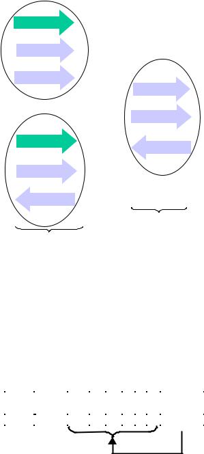
Low-speed timings are determined in the same way for:
TLEOPD and TLHESK
Figure 7-53. Hub EOP Delay and EOP Skew for Low-/full-speed
193
Universal Serial Bus Specification Revision 2.0
194
Universal Serial Bus Specification Revision 2.0
Chapter 8
Protocol Layer
This chapter presents a bottom-up view of the USB protocol, starting with field and packet definitions. This is followed by a description of packet transaction formats for different transaction types. Link layer flow control and transaction level fault recovery are then covered. The chapter finishes with a discussion of retry synchronization, babble, loss of bus activity recovery, and high-speed PING protocol.
8.1 Byte/Bit Ordering
Bits are sent out onto the bus least-significant bit (LSb) first, followed by the next LSb, through to the mostsignificant bit (MSb) last. In the following diagrams, packets are displayed such that both individual bits and fields are represented (in a left to right reading order) as they would move across the bus.
Multiple byte fields in standard descriptors, requests, and responses are interpreted as and moved over the bus in little-endian order, i.e., LSB to MSB.
8.2 SYNC Field
All packets begin with a synchronization (SYNC) field, which is a coded sequence that generates a maximum edge transition density. It is used by the input circuitry to align incoming data with the local clock. A SYNC from an initial transmitter is defined to be eight bits in length for full/low-speed and 32 bits for high-speed. Received SYNC fields may be shorter as described in Chapter 7. SYNC serves only as a synchronization mechanism and is not shown in the following packet diagrams (refer to Section 7.1.10). The last two bits in the SYNC field are a marker that is used to identify the end of the SYNC field and, by inference, the start of the PID.
8.3 Packet Field Formats
Field formats for the token, data, and handshake packets are described in the following section. Packet bit definitions are displayed in unencoded data format. The effects of NRZI coding and bit stuffing have been removed for the sake of clarity. All packets have distinct Startand End-of-Packet delimiters. The Start-of- Packet (SOP) delimiter is part of the SYNC field, and the End-of-Packet (EOP) delimiter is described in Chapter 7.
8.3.1 Packet Identifier Field
A packet identifier (PID) immediately follows the SYNC field of every USB packet. A PID consists of a four-bit packet type field followed by a four-bit check field as shown in Figure 8-1. The PID indicates the type of packet and, by inference, the format of the packet and the type of error detection applied to the packet. The four-bit check field of the PID ensures reliable decoding of the PID so that the remainder of the packet is interpreted correctly. The PID check field is generated by performing a one’s complement of the packet type field. A PID error exists if the four PID check bits are not complements of their respective packet identifier bits.
(LSb) |
|
|
|
|
|
|
|
|
|
|
(MSb) |
||||
PID 0 |
|
|
|
|
|
|
|
|
|
|
|
|
|
|
|
PID 1 |
PID 2 |
PID 3 |
|
PID 0 |
|
PID 1 |
|
PID 2 |
|
PID 3 |
|||||
|
|
|
|
|
|
|
|
|
|
|
|
|
|
|
|
Figure 8-1. PID Format
The host and all functions must perform a complete decoding of all received PID fields. Any PID received with a failed check field or which decodes to a non-defined value is assumed to be corrupted and it, as well
195

Universal Serial Bus Specification Revision 2.0
as the remainder of the packet, is ignored by the packet receiver. If a function receives an otherwise valid PID for a transaction type or direction that it does not support, the function must not respond. For example, an IN-only endpoint must ignore an OUT token. PID types, codings, and descriptions are listed in
Table 8-1.
Table 8-1. PID Types
PID Type |
PID Name |
PID<3:0>* |
Token |
OUT |
0001B |
|
IN |
1001B |
|
SOF |
0101B |
|
SETUP |
1101B |
|
|
|
Description
Address + endpoint number in host-to-function transaction
Address + endpoint number in function-to-host transaction
Start-of-Frame marker and frame number
Address + endpoint number in host-to-function transaction for SETUP to a control pipe
|
Data |
DATA0 |
0011B |
|
Data packet PID even |
|||
|
|
|
DATA1 |
1011B |
|
Data packet PID odd |
||
|
|
|
DATA2 |
0111B |
|
Data packet PID high-speed, high bandwidth isochronous |
||
|
|
|
|
|
|
|
|
transaction in a microframe (see Section 5.9.2 for more |
|
|
|
|
|
|
|
|
information) |
|
|
|
MDATA |
1111B |
|
Data packet PID high-speed for split and high bandwidth |
||
|
|
|
|
|
|
|
|
isochronous transactions (see Sections 5.9.2, 11.20, and |
|
|
|
|
|
|
|
|
11.21 for more information) |
|
|
|
|
|
|
|
|
|
|
Handshake |
ACK |
0010B |
|
Receiver accepts error-free data packet |
|||
|
|
|
NAK |
1010B |
|
Receiving device cannot accept data or transmitting |
||
|
|
|
|
|
|
|
|
device cannot send data |
|
|
|
STALL |
1110B |
|
Endpoint is halted or a control pipe request is not |
||
|
|
|
|
|
|
|
|
supported |
|
|
|
NYET |
0110B |
|
No response yet from receiver (see Sections 8.5.1 and |
||
|
|
|
|
|
|
|
11.17-11.21) |
|
|
|
|
|
|
|
|
|
|
|
Special |
PRE |
1100B |
|
(Token) Host-issued preamble. Enables downstream bus |
|||
|
|
|
|
|
|
|
|
traffic to low-speed devices. |
|
|
|
ERR |
1100B |
|
(Handshake) Split Transaction Error Handshake (reuses |
||
|
|
|
|
|
|
|
|
PRE value) |
|
|
|
SPLIT |
1000B |
|
(Token) High-speed Split Transaction Token (see |
||
|
|
|
|
|
|
|
|
Section 8.4.2) |
|
|
|
PING |
0100B |
|
(Token) High-speed flow control probe for a bulk/control |
||
|
|
|
Reserved |
0000B |
|
endpoint (see Section 8.5.1) |
||
|
|
|
|
|
||||
|
|
|
|
|
|
|
|
Reserved PID |
|
|
|
|
|
|
|
|
|
*Note: PID bits are shown in MSb order. When sent on the USB, the rightmost bit (bit 0) will be sent first. |
||||||||
196
Universal Serial Bus Specification Revision 2.0
PIDs are divided into four coding groups: token, data, handshake, and special, with the first two transmitted PID bits (PID<0:1>) indicating which group. This accounts for the distribution of PID codes.
8.3.2 Address Fields
Function endpoints are addressed using two fields: the function address field and the endpoint field. A function needs to fully decode both address and endpoint fields. Address or endpoint aliasing is not permitted, and a mismatch on either field must cause the token to be ignored. Accesses to non-initialized endpoints will also cause the token to be ignored.
8.3.2.1 Address Field
The function address (ADDR) field specifies the function, via its address, that is either the source or destination of a data packet, depending on the value of the token PID. As shown in Figure 8-2, a total of 128 addresses are specified as ADDR<6:0>. The ADDR field is specified for IN, SETUP, and OUT tokens and the PING and SPLIT special token. By definition, each ADDR value defines a single function. Upon reset and power-up, a function’s address defaults to a value of zero and must be programmed by the host during the enumeration process. Function address zero is reserved as the default address and may not be assigned to any other use.
(LSb) |
(MSb) |
||||||
Addr 0 |
Addr 1 |
Addr 2 |
Addr 3 |
Addr 4 |
Addr 5 |
Addr 6 |
|
|
|
|
|
|
|
|
|
Figure 8-2. ADDR Field
8.3.2.2 Endpoint Field
An additional four-bit endpoint (ENDP) field, shown in Figure 8-3, permits more flexible addressing of functions in which more than one endpoint is required. Except for endpoint address zero, endpoint numbers are function-specific. The endpoint field is defined for IN, SETUP, and OUT tokens and the PING special token. All functions must support a control pipe at endpoint number zero (the Default Control Pipe). Lowspeed devices support a maximum of three pipes per function: a control pipe at endpoint number zero plus two additional pipes (either two control pipes, a control pipe and a interrupt endpoint, or two interrupt endpoints). Full-speed and high-speed functions may support up to a maximum of 16 IN and OUT endpoints.
(LSb) |
|
(MSb) |
|
Endp 0 |
Endp 1 |
Endp 2 |
Endp 3 |
|
|
|
|
Figure 8-3. Endpoint Field
8.3.3 Frame Number Field
The frame number field is an 11-bit field that is incremented by the host on a per-frame basis. The frame number field rolls over upon reaching its maximum value of 7FFH and is sent only in SOF tokens at the start of each (micro)frame.
8.3.4 Data Field
The data field may range from zero to 1,024 bytes and must be an integral number of bytes. Figure 8-4 shows the format for multiple bytes. Data bits within each byte are shifted out LSb first.
197
Universal Serial Bus Specification Revision 2.0
(MSb) |
|
(LSb) |
|
|
|
|
|
|
|
(MSb) |
(LSb) |
|
D 7 |
|
D 0 |
D 1 |
D 2 |
D 3 |
D 4 |
D 5 |
|
D 6 |
D 7 |
|
D 0 |
|
|
|
|
|
|
|
|
|
|
|
|
|
Byte N-1 |
|
|
|
|
Byte N |
|
|
|
Byte N+1 |
|||
|
|
|
|
Figure 8-4. Data Field Format |
|
|
|
|
||||
Data packet size varies with the transfer type, as described in Chapter 5.
8.3.5 Cyclic Redundancy Checks
Cyclic redundancy checks (CRCs) are used to protect all non-PID fields in token and data packets. In this context, these fields are considered to be protected fields. The PID is not included in the CRC check of a packet containing a CRC. All CRCs are generated over their respective fields in the transmitter before bit stuffing is performed. Similarly, CRCs are decoded in the receiver after stuffed bits have been removed.
Token and data packet CRCs provide 100% coverage for all singleand double-bit errors. A failed CRC is considered to indicate that one or more of the protected fields is corrupted and causes the receiver to ignore those fields and, in most cases, the entire packet.
For CRC generation and checking, the shift registers in the generator and checker are seeded with an allones pattern. For each data bit sent or received, the high order bit of the current remainder is XORed with the data bit and then the remainder is shifted left one bit and the low-order bit set to zero. If the result of that XOR is one, then the remainder is XORed with the generator polynomial.
When the last bit of the checked field is sent, the CRC in the generator is inverted and sent to the checker MSb first. When the last bit of the CRC is received by the checker and no errors have occurred, the remainder will be equal to the polynomial residual.
A CRC error exists if the computed checksum remainder at the end of a packet reception does not match the residual.
Bit stuffing requirements must be met for the CRC, and this includes the need to insert a zero at the end of a CRC if the preceding six bits were all ones.
8.3.5.1 Token CRCs
A five-bit CRC field is provided for tokens and covers the ADDR and ENDP fields of IN, SETUP, and OUT tokens or the time stamp field of an SOF token. The PING and SPLIT special tokens also include a five-bit CRC field. The generator polynomial is:
G(X) = X5 + X2 + 1
The binary bit pattern that represents this polynomial is 00101B. If all token bits are received without error, the five-bit residual at the receiver will be 01100B.
8.3.5.2 Data CRCs
The data CRC is a 16-bit polynomial applied over the data field of a data packet. The generating polynomial is:
G(X) = X16 + X15 + X2 + 1
The binary bit pattern that represents this polynomial is 1000000000000101B. If all data and CRC bits are received without error, the 16-bit residual will be 1000000000001101B.
198
Universal Serial Bus Specification Revision 2.0
8.4 Packet Formats
This section shows packet formats for token, data, and handshake packets. Fields within a packet are displayed in these figures in the order in which bits are shifted out onto the bus.
8.4.1 Token Packets
Figure 8-5 shows the field formats for a token packet. A token consists of a PID, specifying either IN, OUT, or SETUP packet type and ADDR and ENDP fields. The PING special token packet also has the same fields as a token packet. For OUT and SETUP transactions, the address and endpoint fields uniquely identify the endpoint that will receive the subsequent Data packet. For IN transactions, these fields uniquely identify which endpoint should transmit a Data packet. For PING transactions, these fields uniquely identify which endpoint will respond with a handshake packet. Only the host can issue token packets. An IN PID defines a Data transaction from a function to the host. OUT and SETUP PIDs define Data transactions from the host to a function. A PING PID defines a handshake transaction from the function to the host.
|
(lsb) |
|
|
(msb) |
|
|
|
|
|
|
|
Field |
|
PID |
ADDR |
ENDP |
CRC5 |
|
|
|
|
|
|
Bits |
8 |
7 |
4 |
5 |
|
|
|
|
|
|
|
Figure 8-5. Token Format
Token packets have a five-bit CRC that covers the address and endpoint fields as shown above. The CRC does not cover the PID, which has its own check field. Token and SOF packets are delimited by an EOP after three bytes of packet field data. If a packet decodes as an otherwise valid token or SOF but does not terminate with an EOP after three bytes, it must be considered invalid and ignored by the receiver.
8.4.2 Split Transaction Special Token Packets
USB defines a special token for split transactions: SPLIT. This is a 4 byte token packet compared to other normal 3 byte token packets. The split transaction token packet provides additional transaction types with additional transaction specific information. The split transaction token is used to support split transactions between the host controller communicating with a hub operating at high speed with full-/low-speed devices to some of its downstream facing ports. There are two split transactions defined that use the SPLIT special token: a start-split transaction (SSPLIT) and a complete-split transaction (CSPLIT). A field in the SPLIT special token, described in the following sections, indicates the specific split transaction.
8.4.2.1 Split Transactions
A high-speed split transaction is used only between the host controller and a hub when the hub has full- /low-speed devices attached to it. This high-speed split transaction is used to initiate a full-/low-speed transaction via the hub and some full-/low-speed device endpoint. The high-speed split transaction also allows the completion status of the full-/low-speed transaction to be retrieved from the hub. This approach allows the host controller to start a full-/low-speed transaction via a high-speed transaction and then continue with other high-speed transactions without having to wait for the full-/low-speed transaction to proceed/complete at the slower speed. See Chapter 11 for more details about the state machines and transaction definitions of split transactions.
A high-speed split transaction has two parts: a start-split and a complete-split. Split transactions are only defined to be used between the host controller and a hub. No other high-speed or full-/low-speed devices ever use split transactions.
199
Universal Serial Bus Specification Revision 2.0
Figure 8-6 shows the packets composing a generic start-split transaction. There are two packets in the token phase: the SPLIT special token and a full-/low-speed token. Depending on the direction of data transfer and whether a handshake is defined for the transaction type, the token phase is optionally followed by a data packet and a handshake packet. Start split transactions can consist of 2, 3, or 4 packets as determined by the specific transfer type and data direction.
SSPLIT |
|
FS/LS Token |
|
DATAx |
|
Handshake |
Token |
|
|
|
|||
|
|
|
|
|
|
Token Phase
Figure 8-6. Packets in a Start-split Transaction
Figure 8-7 shows the packets composing a generic complete-split transaction. There are two packets in the token phase: the SPLIT special token and a full-/low-speed token. A data or handshake packet follows the token phase packets in the complete-split depending on the data transfer direction and specific transaction type. Complete split transactions can consist of 2 or 3 packets as determined by the specific transfer type and data direction.
|
|
|
|
|
|
|
|
|
|
DATAx |
|
|
|
|
|
||
|
|
|
|
||
|
|
|
|
|
|
CSPLIT |
|
FS/LS Token |
|
|
|
|
|
|
|
||
|
|
or |
|||
Token |
|
|
|||
|
|
|
|
|
|
|
|
|
|
|
|
|
|
|
|
|
|
|
|
|
|
|
|
Handshake
Token Phase
Figure 8-7. Packets in a Complete-split Transaction
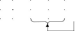
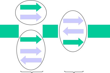
The results of a split transaction are returned by a complete-split transaction. Figure 8-8 shows this conceptual “conversion” for an example interrupt IN transfer type. The host issues a start-split (indicated with 1) to the hub and then can proceed with other high-speed transactions. The start-split causes the hub to issue a full-/low-speed IN token sometime later (indicated by 2). The device responds to the IN token (in this example) with a data packet and the hub responds with a handshake to the device. Finally, the host sometime later issues a complete-split (indicated by 3) to retrieve the data provided by the device. Note that in the example, the hub provided the full-/low-speed handshake (ACK in this example) to the device endpoint before the complete-split, and the complete-split did not provide a high-speed handshake to the hub.
200
|
Universal Serial Bus Specification Revision 2.0 |
|
|
1 |
|
|
|
Start |
SSPLIT |
2 |
|
Split |
|
||
Full/Low-Speed |
|
||
|
|
|
|
|
IN Token |
IN Token |
|
|
|
|
|
Host |
Hub |
Data0 |
Device |
|
CSPLIT |
ACK |
|
|
|
|
|
3 |
IN Token |
|
|
|
|
|
|
Complete |
Data0 |
|
|
Split |
|
|
|
|
High-Speed |
Full-/Low-Speed |
|
|
Bus |
Bus |
|
Figure 8-8. Relationship of Interrupt IN Transaction to High-speed Split Transaction
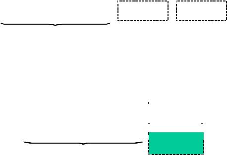
A normal full-/low-speed OUT transaction is similarly conceptually “converted” into start-split and complete-split transactions. Figure 8-9 shows this “conversion” for an example interrupt OUT transfer type. The host issues a start-split transaction consisting of a SSPLIT special token, an OUT token, and a DATA packet. The hub sometime later issues the OUT token and DATA packet on the full-/low- speed bus. The device responds with a handshake. Sometime later, the host issues the complete-split transaction and the hub responds with the results (either full-/low-speed data or handshake) provided by the device.
201
Universal Serial Bus Specification Revision 2.0
1 |
SSPLIT |
|
|
|
|
|
|
|
|
Start |
OUT Token |
2 |
|
|
Split |
Full/Low-speed |
|
||
|
|
|
|
|
|
Data0 |
OUT Token |
|
|
|
|
|
|
|
Host |
|
|
|
|
|
Hub |
Device |
||
|
Data0 |
|||
|
CSPLIT |
|
ACK |
|
|
|
|
||
|
|
|
|
|
3 |
OUT Token |
|
|
|
|
|
|
|
|
Complete
Split
ACK
Full-/Low-Speed
High-Speed Bus
Bus
Figure 8-9. Relationship of Interrupt OUT Transaction to High-speed Split OUT Transaction
The next two sections describe the fields composing the detailed startand complete-split token packets. Figure 8-10 and Figure 8-12 show the fields in the split-transaction token packet. The SPLIT special token follows the general token format and starts with a PID field (after a SYNC) and ends with a CRC5 field (and EOP). Start-split and complete-split token packets are both 4 bytes long. SPLIT transactions must only originate from the host. The start-split token is defined in Section 8.4.2.2 and the complete-split token is defined in Section 8.4.2.3.
8.4.2.2 Start-Split Transaction Token
|
(lsb) |
|
|
|
|
|
|
(msb) |
|
|
|
|
|
|
|
|
|
|
|
Field |
|
SPLIT |
Hub |
SC |
Port |
S |
E |
ET |
CRC5 |
|
|
PID |
Addr |
|
|
|
|
|
|
Bits |
8 |
7 |
1 |
7 |
1 |
1 |
2 |
5 |
|
Figure 8-10. Start-split (SSPLIT) Token
The Hub addr field contains the USB device address of the hub supporting the specified full-/low-speed device for this full-/low-speed transaction. This field has the same definition as the ADDR field definition in Section 8.3.2.1.
A SPLIT special token packet with the SC (Start/Complete) field set to zero indicates that this is a start-split transaction (SSPLIT).
The Port field contains the port number of the target hub for which this full-/low-speed transaction is destined. As shown in Figure 8-11, a total of 128 ports are specified as PORT<6:0>. The host must correctly set the port field for single and multiple TT hub implementations. A single TT hub implementation may ignore the port field.
202