

usb_2.0_english
.pdfUniversal Serial Bus Specification Revision 2.0
6.6.2 Construction
Raw materials used in the fabrication of this cable must be of such quality that the fabricated cable is capable of meeting or exceeding the mechanical and electrical performance criteria of the most current USB Specification revision and all applicable domestic and international safety/testing agency requirements; e.g., UL, CSA, BSA, NEC, etc., for electronic signaling and power distribution cables in its category.
|
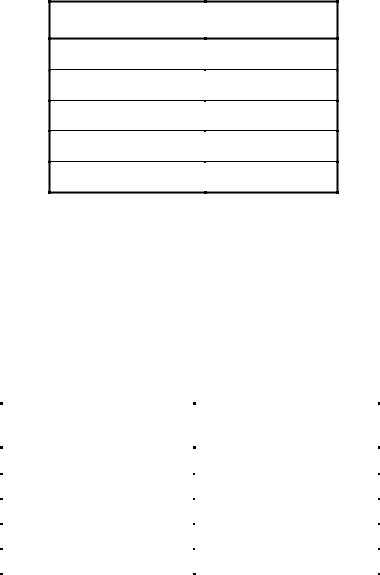
Table 6-2. Power Pair |
|
American Wire |
Nominal Conductor |
Stranded Tinned |
Gauge (AWG) |
Outer Diameter |
Conductors |
|
|
|
|
0.381 mm (0.015”) |
7 x 36 |
28 |
|
|
|
0.406 mm (0.016”) |
19 x 40 |
|
|
|
|
0.483 mm (0.019”) |
7 x 34 |
26 |
|
|
|
0.508 mm (0.020”) |
19 x 38 |
|
|
|
|
0.610 mm (0.024”) |
7 x 32 |
24 |
|
|
|
0.610 mm (0.024”) |
19 x 36 |
|
|
|
|
0.762 mm (0.030”) |
7 x 30 |
22 |
|
|
|
0.787 mm (0.031”) |
19 x 34 |
|
|
|
|
0.890 mm (0.035”) |
7 x 28 |
20 |
|
|
|
0.931 mm (0.037”) |
19 x 32 |
|
|
|
Note: Minimum conductor construction must be stranded tinned copper.
Non-Twisted Power Pair:
A.Wire Gauge: Minimum 28 AWG or as specified by the user contingent upon the specified cable length. Refer to Table 6-2.
B.Wire Insulation: Semirigid polyvinyl chloride (PVC).
1.Nominal Insulation Wall Thickness: 0.25 mm (0.010”)
2.Typical Power (VBUS) Conductor: Red Insulation
3.Typical Ground Conductor: Black Insulation
Signal Pair:
A. Wire Gauge: 28 AWG minimum. Refer to Table 6-3.
103
Universal Serial Bus Specification Revision 2.0
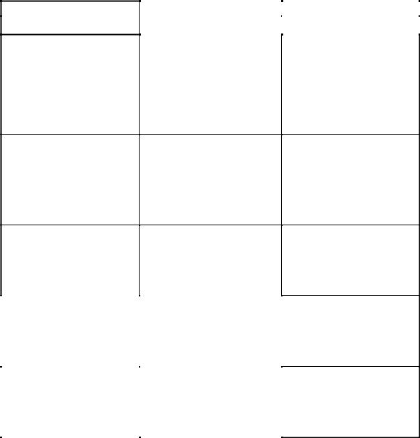
|
Table 6-3. Signal Pair |
|
American Wire |
Nominal Conductor |
Stranded Tinned |
Gauge (AWG) |
Outer Diameter |
Conductors |
|
|
|
|
0.381 mm (0.015”) |
7 x 36 |
28 |
|
|
|
0.406 mm (0.016”) |
19 x 40 |
|
|
|
Note: Minimum conductor construction must be stranded tinned copper.
B.Wire Insulation: High-density polyethylene (HDPE), alternately foamed polyethylene or foamed polypropylene
1.Nominal Insulation Wall Thickness: 0.31 mm (0.012”)
2.Typical Data Plus (+) Conductor: Green Insulation
3.Typical Data Minus (-) Conductor: White Insulation
C.Nominal Twist Ratio (not required for low-speed): One full twist every 60 mm (2.36”) to 80 mm (3.15”)
Aluminum Metallized Polyester Inner Shield (required for low-speed):
A.Substrate Material: Polyethylene terephthalate (PET) or equivalent material
B.Metallizing: Vacuum deposited aluminum
C.Assembly:
1.The aluminum metallized side of the inner shield must be positioned facing out to ensure direct contact with the drain wire.
2.The aluminum metallized inner shield must overlap by approximately one-quarter turn.
Drain Wire (required for low-speed):
A.Wire Gauge: Minimum 28 AWG stranded tinned copper (STC) non-insulated. Refer to Table 6-4.
Table 6-4. Drain Wire Signal Pair
American Wire |
Nominal Conductor |
Stranded Tinned |
Gauge (AWG) |
Outer Diameter |
Conductors |
|
|
|
|
0.381 mm (0.015”) |
7 x 36 |
28 |
|
|
|
0.406 mm (0.016”) |
19 x 40 |
|
|
|
Interwoven (Braided) Tinned Copper Wire (ITCW) Outer Shield (recommended but not required for lowspeed):
A.Coverage Area: Minimum 65%.
B.Assembly: The interwoven (braided) tinned copper wire outer shield must encase the aluminum metallized PET shielded power and signal pairs and must be in direct contact with the drain wire.
Outer Polyvinyl Chloride (PVC) Jacket:
A.Assembly: The outer PVC jacket must encase the fully shielded power and signal pairs and must be in direct contact with the tinned copper outer shield.
104
Universal Serial Bus Specification Revision 2.0
B. Nominal Wall Thickness: 0.64 mm (0.025”).
Marking: The cable must be legibly marked using contrasting color permanent ink.
A.Minimum marking information for high-/full-speed cable must include:
USB SHIELDED <Gauge/2C + Gauge/2C> UL CM 75 oC — UL Vendor ID.
B.Minimum marking information for low-speed cable shall include: USB specific marking is not required for low-speed cable.
Nominal Fabricated Cable Outer Diameter:
This is a nominal value and may vary slightly from manufacturer to manufacturer as a function of the conductor insulating materials and conductor specified. Refer to Table 6-5.
Table 6-5. Nominal Cable Diameter
Shielded USB
Cable Configuration
28/28
28/26
28/24
28/22
28/20
Nominal Outer
Cable Diameter
4.06 mm (0.160”)
4.32 mm (0.170”)
4.57 mm (0.180”)
4.83 mm (0.190”)
5.21 mm (0.205”)
6.6.3 Electrical Characteristics
All electrical characteristics must be measured at or referenced to +20 oC (68 oF).
Voltage Rating: 30 V rms maximum.
Conductor Resistance: Conductor resistance must be measured in accordance with ASTM-D-4566 Section 13. Refer to Table 6-6.
Conductor Resistance Unbalance (Pairs): Conductor resistance unbalance between two (2) conductors of any pair must not exceed five percent (5%) when measured in accordance with ASTM-D-4566 Section 15.
The DC resistance from plug shell to plug shell (or end of integrated cable) must be less than 0.6 ohms.
Table 6-6. Conductor Resistance
American |
Ohms (Ω ) / 100 Meters |
Wire Gauge (AWG) |
Maximum |
|
|
28 |
23.20 |
|
|
26 |
14.60 |
|
|
24 |
9.09 |
|
|
22 |
5.74 |
|
|
20 |
3.58 |
|
|
105

Universal Serial Bus Specification Revision 2.0
6.6.4 Cable Environmental Characteristics
Temperature Range:
A.Operating Temperature Range: 0 oC to +50 oC
B.Storage Temperature Range: -20 oC to +60 oC
C.Nominal Temperature Rating: +20 oC
Flammability: All plastic materials used in the fabrication of this product shall meet or exceed the requirements of NEC Article 800 for communications cables Type CM (Commercial).
6.6.5 Listing
The product shall be UL listed per UL Subject 444, Class 2, Type CM for Communications Cable Requirements.
6.7 Electrical, Mechanical , and Environmental Compliance Standards
Table 6-7 lists the minimum test criteria for all USB cable, cable assemblies, and connectors.
Table 6-7. USB Electrical, Mechanical, and Environmental Compliance Standards
|
Test Description |
|
Test Procedure |
|
Performance Requirement |
|
|
|
|
|
|||
|
|
|
|
|||
|
|
|
|
|
|
|
Visual and Dimensional
Inspection
Insulation Resistance
Dielectric
Withstanding Voltage
EIA 364-18
Visual, dimensional, and functional inspection in accordance with the USB quality inspection plans.
EIA 364-21
The object of this test procedure is to detail a standard method to assess the insulation resistance of USB connectors. This test procedure is used to determine the resistance offered by the insulation materials and the various seals of a connector to a DC potential tending to produce a leakage of current through or on the surface of these members.
EIA 364-20
The object of this test procedure is to detail a test method to prove that a USB connector can operate safely at its rated voltage and withstand momentary over-potentials due to switching, surges, and/or other similar phenomena.
Must meet or exceed the requirements specified by the most current version of Chapter 6 of the USB Specification.
1,000 MΩ minimum.
The dielectric must withstand 500 V AC for one minute at sea level.
106
Universal Serial Bus Specification Revision 2.0
Table 6-7. USB Electrical, Mechanical, and Environmental Compliance Standards (Continued)
Test Description
Low Level
Contact Resistance
Contact Current
Rating
Contact Capacitance
Test Procedure |
Performance Requirement |
|
|
|
EIA 364-23
The object of this test is to detail a standard method to measure the electrical resistance across a pair of mated contacts such that the insulating films, if present, will not be broken or asperity melting will not occur.
30 mΩ maximum when measured at 20 mV maximum open circuit at 100 mA. Mated test contacts must be in a connector housing.
EIA 364-70 — Method B
The object of this test procedure is to detail a standard method to assess the current carrying capacity of mated USB connector contacts.
EIA 364-30
The object of this test is to detail a standard method to determine the capacitance between conductive elements of a USB connector.
1.5 A at 250 V AC minimum when measured at an ambient temperature of 25 °C. With power applied to the contacts, the ∆ T must not exceed +30 °C at any point in the USB connector under test.
2 pF maximum unmated per contact.
|
EIA 364-13 |
|
Insertion Force |
The object of this test is to detail a |
|
standard method for determining |
||
|
||
|
the mechanical forces required for |
|
|
inserting a USB connector. |
|
|
|
35 Newtons maximum at a maximum rate of 12.5 mm (0.492”) per minute.
|
EIA 364-13 |
|
Extraction Force |
The object of this test is to detail a |
|
standard method for determining |
||
|
||
|
the mechanical forces required for |
|
|
extracting a USB connector. |
|
|
|
10 Newtons minimum at a maximum rate of 12.5 mm (0.492”) per minute.
107

Universal Serial Bus Specification Revision 2.0
Table 6-7. USB Electrical, Mechanical, and Environmental Compliance Standards (Continued)
Test Description |
Test Procedure |
Performance Requirement |
|
|
|
|
Durability
Cable Pull-Out
Physical Shock
EIA 364-09
The object of this test procedure is to detail a uniform test method for determining the effects caused by subjecting a USB connector to the conditioning action of insertion and extraction, simulating the expected life of the connectors. Durability cycling with a gauge is intended only to produce mechanical stress. Durability performed with mating components is intended to produce both mechanical and wear stress.
1,500 insertion/extraction cycles at a maximum rate of 200 cycles per hour.
EIA 364-38
Test Condition A
The object of this test procedure is to detail a standard method for determining the holding effect of a USB plug cable clamp without causing any detrimental effects upon the cable or connector components when the cable is subjected to inadvertent axial tensile loads.
EIA 364-27
Test Condition H
The object of this test procedure is to detail a standard method to assess the ability of a USB connector to withstand specified severity of mechanical shock.
After the application of a steady state axial load of 40 Newtons for one minute.
No discontinuities of 1 s or longer duration when mated USB connectors are subjected to 11 ms duration 30 Gs half-sine shock pulses. Three shocks in each direction applied along three mutually perpendicular planes for a total of 18 shocks.
108

Universal Serial Bus Specification Revision 2.0
Table 6-7. USB Electrical, Mechanical, and Environmental Compliance Standards (Continued)
Test Description
Random Vibration
Thermal Shock
Humidity Life
Test Procedure |
|
Performance Requirement |
|
|
|
||
|
|
||
|
|
|
|
EIA 364-28
Test Condition V Test Letter A
This test procedure is applicable to USB connectors that may, in service, be subjected to conditions involving vibration. Whether a USB connector has to function during vibration or merely to survive conditions of vibration should be clearly stated by the detailed product specification. In either case, the relevant specification should always prescribe the acceptable performance tolerances.
No discontinuities of 1 s or longer duration when mated USB connectors are subjected to
5.35 Gs RMS. 15 minutes in each of three mutually perpendicular planes.
EIA 364-32
Test Condition I
The object of this test is to determine the resistance of a USB connector to exposure at extremes of high and low temperatures and to the shock of alternate exposures to these extremes, simulating the worst case conditions for storage, transportation, and application.
EIA 364-31
Test Condition A Method III
The object of this test procedure is to detail a standard test method for the evaluation of the properties of materials used in USB connectors as they are influenced by the effects of high humidity and heat.
10 cycles –55 ° C and +85 ° C. The USB connectors under test must be mated.
168 hours minimum (seven complete cycles). The USB connectors under test must be tested in accordance with
EIA 364-31.
EIA 364-52
The object of this test procedure is to detail a uniform test method for determining USB connector
Solderability solderability. The test procedure contained herein utilizes the solder dip technique. It is not intended to test or evaluate solder cup, solder eyelet, other hand-soldered type, or SMT type terminations.
USB contact solder tails must pass 95% coverage after one hour steam aging as specified in Category 2.
109

Universal Serial Bus Specification Revision 2.0
Table 6-7. USB Electrical, Mechanical, and Environmental Compliance Standards (Continued)
|
Test Description |
|
Test Procedure |
|
Performance Requirement |
|
|
|
|
|
|||
|
|
|
|
|||
|
|
|
|
|
|
|
UL 94 V-0
This procedure is to ensure Flammability thermoplastic resin compliance to
UL flammability standards.
The manufacturer will require its thermoplastic resin vendor to supply a detailed C of C with each resin shipment. The C of C shall clearly show the resin’s UL listing number, lot number, date code, etc.
Cable Impedance
(Only required for high-/full-speed)
The object of this test is to insure the signal conductors have the proper impedance.
1.Connect the Time Domain Reflectometer (TDR) outputs to the impedance/delay/skew
test fixture (Note 1). Use separate 50 Ω cables for the plus (or true) and minus (or complement) outputs. Set the TDR head to differential TDR mode.
2.Connect the Series "A" plug of the cable to be tested to the text fixture, leaving the other end open-circuited.
3.Define a waveform composed of the difference between the true and complement waveforms, to allow measurement of differential impedance.
4.Measure the minimum and maximum impedances found between the connector and the open circuited far end of the cable.
Impedance must be in the range specified in Table 7-9 (ZO).
110

Universal Serial Bus Specification Revision 2.0
Table 6-7. USB Electrical, Mechanical, and Environmental Compliance Standards (Continued)
Test Description |
Test Procedure |
Performance Requirement |
|
|
|
|
Signal Pair Attenuation
(Only required for high-/full-speed)
The object of this test is to insure that adequate signal strength is presented to the receiver to maintain a low error rate.
1.Connect the Network Analyzer output port (port 1) to the input connector on the attenuation test fixture (Note 2).
2.Connect the Series “A” plug of the cable to be tested to the test fixture, leaving the other end open-circuited.
3.Calibrate the network analyzer and fixture using the appropriate calibration standards over the desired frequency range.
4.Follow the method listed in Hewlett Packard Application Note 380-2 to measure the open-ended response of the cable.
5.Short circuit the Series “B” end (or bare leads end, if a captive cable) and measure the shortcircuit response.
6.Using the software in H-P App. Note 380-2 or equivalent, calculate the cable attenuation accounting for resonance effects in the cable as needed.
Refer to Section 7.1.17 for frequency range and allowable attenuation.
111

Universal Serial Bus Specification Revision 2.0
Table 6-7. USB Electrical, Mechanical, and Environmental Compliance Standards (Continued)
Test Description |
Test Procedure |
Performance Requirement |
|
|
|
|
The purpose of the test is to verify the end to end propagation of the cable.
1. Connect one output of the TDR sampling head to the D+ and D- inputs of the impedance/delay/skew test fixture (Note 1). Use one 50 Ω cable for each signal and set the TDR head to differential TDR mode.
2. Connect the cable to be tested to the test fixture. If detachable, plug both connectors in to the matching fixture connectors. If captive,
Propagation Delay plug the series “A” plug into the matching fixture connector and solder the stripped leads on the other end to the test fixture.
3. Measure the propagation delay of the test fixture by connecting a short piece of wire across the fixture from input to output and recording the delay.
4. Remove the short piece of wire and remeasure the propagation delay. Subtract from it the delay of the test fixture measured in the previous step.
High-/full-speed.
See Section 7.1.1.1,
Section 7.1.4, Section 7.1.16, and
Table 7-9 (TFSCBL).
Low-speed.
See Section 7.1.1.2,
Section 7.1.16, and Table 7-9
(TLSCBL).
112