

usb_2.0_english
.pdfUniversal Serial Bus Specification Revision 2.0
|
|
|
|
|
|
|
|
|
|
Port |
|
Port |
|
Port |
|
||
#1 |
|
#2 |
|
#3 |
|
|
||
Upstream |
HUB |
Port |
|
|||||
|
||||||||
Port |
#4 |
|
||||||
|
|
|
||||||
|
Port |
|
Port |
|
Port |
|
||
#7 |
|
#6 |
|
#5 |
|
|
||
|
|
|
|
|
|
|
|
|
Figure 4-3. A Typical Hub
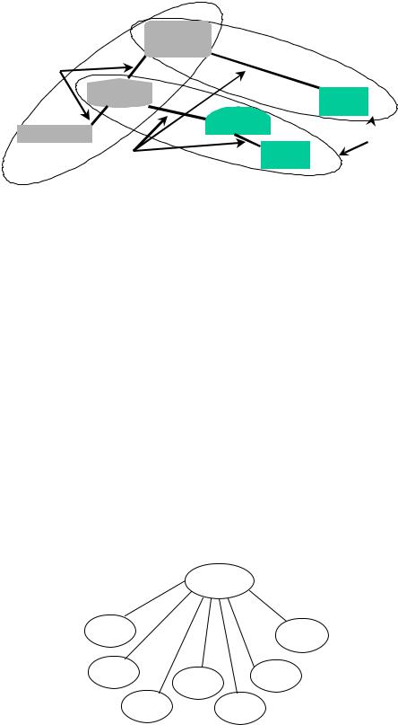
Figure 4-4 illustrates how hubs provide connectivity in a typical desktop computer environment.
USB
|
TYPICAL USB ARCHITECTURAL |
|
|
CONFIGURATION |
|
Hub/Function |
Hub/Function |
Host/Hub |
KBD |
Monitor |
PC |
Pen |
Mouse |
Speaker |
Mic |
Phone |
Hub |
Function |
Function |
Function |
Function |
Function |
Hub |
Figure 4-4. Hubs in a Desktop Computer Environment
23
Universal Serial Specification Revision 2.0
4.8.2.2 Functions
A function is a USB device that is able to transmit or receive data or control information over the bus. A function is typically implemented as a separate peripheral device with a cable that plugs into a port on a hub. However, a physical package may implement multiple functions and an embedded hub with a single USB cable. This is known as a compound device. A compound device appears to the host as a hub with one or more non-removable USB devices.
Each function contains configuration information that describes its capabilities and resource requirements. Before a function can be used, it must be configured by the host. This configuration includes allocating USB bandwidth and selecting function-specific configuration options.
Examples of functions include the following:
•A human interface device such as a mouse, keyboard, tablet, or game controller
•An imaging device such as a scanner, printer, or camera
•A mass storage device such as a CD-ROM drive, floppy drive, or DVD drive
4.9USB Host: Hardware and Software
The USB host interacts with USB devices through the Host Controller. The host is responsible for the following:
•Detecting the attachment and removal of USB devices
•Managing control flow between the host and USB devices
•Managing data flow between the host and USB devices
•Collecting status and activity statistics
•Providing power to attached USB devices
The USB System Software on the host manages interactions between USB devices and host-based device software. There are five areas of interactions between the USB System Software and device software:
•Device enumeration and configuration
•Isochronous data transfers
•Asynchronous data transfers
•Power management
•Device and bus management information
4.10 Architectural Extensions
The USB architecture comprehends extensibility at the interface between the Host Controller Driver and USB Driver. Implementations with multiple Host Controllers, and associated Host Controller Drivers, are possible.
24
Universal Serial Bus Specification Revision 2.0
Chapter 5
USB Data Flow Model
This chapter presents information about how data is moved across the USB. The information in this chapter affects all implementers. The information presented is at a level above the signaling and protocol definitions of the system. Consult Chapter 7 and Chapter 8 for more details about their respective parts of the USB system. This chapter provides framework information that is further expanded in Chapters 9 through 11. All implementers should read this chapter so they understand the key concepts of the USB.
5.1 Implementer Viewpoints
The USB provides communication services between a host and attached USB devices. However, the simple view an end user sees of attaching one or more USB devices to a host, as in Figure 5-1, is in fact a little more complicated to implement than is indicated by the figure. Different views of the system are required to explain specific USB requirements from the perspective of different implementers. Several important concepts and features must be supported to provide the end user with the reliable operation demanded from today’s personal computers. The USB is presented in a layered fashion to ease explanation and allow implementers of particular USB products to focus on the details related to their product.
USB Host |
|
USB Device |
|
||
|
|
|
Figure 5-1. Simple USB Host/Device View
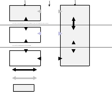
Figure 5-2 shows a deeper overview of the USB, identifying the different layers of the system that will be described in more detail in the remainder of the specification. In particular, there are four focus implementation areas:
•USB Physical Device: A piece of hardware on the end of a USB cable that performs some useful end user function.
•Client Software: Software that executes on the host, corresponding to a USB device. This client software is typically supplied with the operating system or provided along with the USB device.
•USB System Software: Software that supports the USB in a particular operating system. The USB System Software is typically supplied with the operating system, independently of particular USB devices or client software.
•USB Host Controller (Host Side Bus Interface): The hardware and software that allows USB devices to be attached to a host.
There are shared rights and responsibilities between the four USB system components. The remainder of this specification describes the details required to support robust, reliable communication flows between a function and its client.
25
Universal Serial Bus Specification Revision 2.0
Host |
Interconnect Physical Device |
|
|||
|
|
|
|
|
|
Client SW |
|
|
|
Function |
Function Layer |
|
|
|
|||
|
|
|
|||
|
|
|
|
|
|
|
|
|
|
|
|
|
|
|
|
|
|
|
|
|
|
|
|
|
|
|
|
|
|
|
USB System |
|
|
|
|
USB Logical |
USB Device |
||||
|
|
|
|
|
|||||||
|
|
|
|
|
|||||||
|
SW |
|
|
|
|
Device |
|||||
|
|
|
|
|
Layer |
||||||
|
|
|
|
|
|
|
|
|
|
|
USB Bus |
|
|
|
|
|
|
|
|
|
|
|
|
|
|
|
|
|
|
|
|
|
|
|
|
|
|
|
|
|
|
|
|
|
|
|
|
|
|
|
|
|
|
|
|
|
|
|
|
|
|
|
|
|
|
|
|
|
|
|
|
|
USB Host |
|
|
|
|
USB Bus |
|||||
|
|
|
|
|
Interface Layer |
||||||
|
Controller |
|
|
|
|
Interface |
|||||
|
|
|
|
|
|
||||||
|
|
|
|
|
|
|
|
|
|
|
|
|
|
|
|
|
|
|
|
|
|
|
|
Actual communications flow
Logical communications flow
Implementation Focus Area
Figure 5-2. USB Implementation Areas
As shown in Figure 5-2, the simple connection of a host to a device requires interaction between a number of layers and entities. The USB Bus Interface layer provides physical/signaling/packet connectivity between the host and a device. The USB Device layer is the view the USB System Software has for performing generic USB operations with a device. The Function layer provides additional capabilities to the host via an appropriate matched client software layer. The USB Device and Function layers each have a view of logical communication within their layer that actually uses the USB Bus Interface layer to accomplish data transfer.
The physical view of USB communication as described in Chapters 6, 7, and 8 is related to the logical communication view presented in Chapters 9 and 10. This chapter describes those key concepts that affect USB implementers and should be read by all before proceeding to the remainder of the specification to find those details most relevant to their product.
To describe and manage USB communication, the following concepts are important:
•Bus Topology: Section 5.2 presents the primary physical and logical components of the USB and how they interrelate.
•Communication Flow Models: Sections 5.3 through 5.8 describe how communication flows between the host and devices through the USB and defines the four USB transfer types.
•Bus Access Management: Section 5.11 describes how bus access is managed within the host to support a broad range of communication flows by USB devices.
•Special Consideration for Isochronous Transfers: Section 5.12 presents features of the USB specific to devices requiring isochronous data transfers. Device implementers for non-isochronous devices do not need to read Section 5.12.
26
Universal Serial Bus Specification Revision 2.0
5.2 Bus Topology
There are four main parts to USB topology:
•Host and Devices: The primary components of a USB system
•Physical Topology: How USB elements are connected
•Logical Topology: The roles and responsibilities of the various USB elements and how the USB appears from the perspective of the host and a device
•Client Software-to-function Relationships: How client software and its related function interfaces on a USB device view each other
5.2.1 USB Host
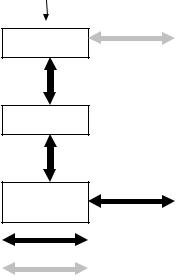
The host’s logical composition is shown in Figure 5-3 and includes the following:
•USB Host Controller
•Aggregate USB System Software (USB Driver, Host Controller Driver, and host software)
•Client
Host
Client SW
USB System SW

USB Host
Controller
Actual communications flow
Logical communications flow
Figure 5-3. Host Composition
The USB host occupies a unique position as the coordinating entity for the USB. In addition to its special physical position, the host has specific responsibilities with regard to the USB and its attached devices. The host controls all access to the USB. A USB device gains access to the bus only by being granted access by the host. The host is also responsible for monitoring the topology of the USB.
For a complete discussion of the host and its duties, refer to Chapter 10.
27
Universal Serial Bus Specification Revision 2.0
5.2.2 USB Devices
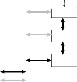
A USB physical device’s logical composition is shown in Figure 5-4 and includes the following:
•USB bus interface
•USB logical device
•Function
USB physical devices provide additional functionality to the host. The types of functionality provided by USB devices vary widely. However, all USB logical devices present the same basic interface to the host. This allows the host to manage the USB-relevant aspects of different USB devices in the same manner.
To assist the host in identifying and configuring USB devices, each device carries and reports configurationrelated information. Some of the information reported is common among all logical devices. Other information is specific to the functionality provided by the device. The detailed format of this information varies, depending on the device class of the device.
For a complete discussion of USB devices, refer to Chapter 9.
Physical Device
Function
USB Logical
Device
USB Bus
Interface
Actual communications flow
Logical communications flow
Figure 5-4. Physical Device Composition
28
Universal Serial Bus Specification Revision 2.0
5.2.3 Physical Bus Topology
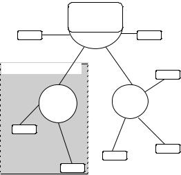
Devices on the USB are physically connected to the host via a tiered star topology, as illustrated in Figure 5-5. USB attachment points are provided by a special class of USB device known as a hub. The additional attachment points provided by a hub are called ports. A host includes an embedded hub called
the root hub. The host provides one or more attachment points via the root hub. USB devices that provide additional functionality to the host are known as functions. To prevent circular attachments, a tiered ordering is imposed on the star topology of the USB. This results in the tree-like configuration illustrated in Figure 5-5.
|
Host |
|
Device |
Root Hub |
Device |
|
|
Compound Device
Device
Hub |
Hub |
Device
Device
Device
Device
Figure 5-5. USB Physical Bus Topology
Multiple functions may be packaged together in what appears to be a single physical device. For example, a keyboard and a trackball might be combined in a single package. Inside the package, the individual functions are permanently attached to a hub and it is the internal hub that is connected to the USB. When multiple functions are combined with a hub in a single package, they are referred to as a compound device. The hub and each function attached to the hub within the compound device is assigned its own device address. A device that has multiple interfaces controlled independently of each other is referred to as a composite device. A composite device has only a single device address. From the host’s perspective, a compound device is the same as a separate hub with multiple functions attached. Figure 5-5 also illustrates a compound device.
29
Universal Serial Bus Specification Revision 2.0
USB 2.0 Host
Controller
High Speed Only
HS Hub |
FS/ LS |
|
Device |
HS Device |
USB 1.1 Hub |
|
|
Full/Low Speed |
FS/ LS |
Device |
 (2 x 12 Mb/s
Capacity)
Figure 5-6. Multiple Full-speed Buses in a High-speed System
The hub plays a special role in a high-speed system. The hub isolates the full-/low-speed signaling environment from the high-speed signaling environment. Figure 5-6 shows a hub operating in high speed supporting a high-speed attached device. The hub also allows USB1.1 hubs to attach and operate at full- /low-speed along with other full-/low-speed only devices. The host controller also directly supports attaching full-/low-speed only devices. Chapter 11 describes the details of how the hub accomplishes the isolation of the two signaling environments.
Each high-speed operating hub essentially adds one (or more) additional full-/low-speed buses; i.e., each hub supports additional (optionally multiple) 12 Mb/s of USB full-/low-speed bandwidth. This allows more full-/low-speed buses to be attached without requiring additional host controllers in a system. Even though there can be several 12 Mb/s full-/low-speed buses, there are only at most 127 USB devices attached to any single host controller.
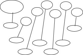
5.2.4 Logical Bus Topology
While devices physically attach to the USB in a tiered, star topology, the host communicates with each logical device as if it were directly connected to the root port. This creates the logical view illustrated in Figure 5-7 that corresponds to the physical topology shown in Figure 5-5. Hubs are logical devices also but are not shown in Figure 5-7 to simplify the picture. Even though most host/logical device activities use this logical perspective, the host maintains an awareness of the physical topology to support processing the removal of hubs. When a hub is removed, all of the devices attached to the hub must be removed from the host’s view of the logical topology. A more complete discussion of hubs can be found in Chapter 11.
|
Host |
||
Logical |
|
Logical |
|
Device |
|
||
|
Device |
||
|
|
||
Logical |
Logical |
Logical |
|
Device |
|||
Device |
|||
Device |
|||
|
|||
Logical |
Logical |
||
|
|||
Device |
|
Device |
|
Figure 5-7. USB Logical Bus Topology
30
Universal Serial Bus Specification Revision 2.0
5.2.5 Client Software-to-function Relationship
Even though the physical and logical topology of the USB reflects the shared nature of the bus, client software (CSw) manipulating a USB function interface is presented with the view that it deals only with its interface(s) of interest. Client software for USB functions must use USB software programming interfaces to manipulate their functions as opposed to directly manipulating their functions via memory or I/O accesses as with other buses (e.g., PCI, EISA, PCMCIA, etc.). During operation, client software should be independent of other devices that may be connected to the USB. This allows the designer of the device and client software to focus on the hardware/software interaction design details. Figure 5-8 illustrates a device designer’s perspective of the relationships of client software and USB functions with respect to the USB logical topology of Figure 5-7.
Client |
CSw |
|
CSw |
Software |
CSw |
CSw |
CSw |
|
|||
|
|
|
|
Func |
CSw |
|
|
|
|
Func |
|
|
|
|
Func
Func Func
Func Func
Figure 5-8. Client Software-to-function Relationships
5.3 USB Communication Flow
The USB provides a communication service between software on the host and its USB function. Functions can have different communication flow requirements for different client-to-function interactions. The USB provides better overall bus utilization by allowing the separation of the different communication flows to a USB function. Each communication flow makes use of some bus access to accomplish communication between client and function. Each communication flow is terminated at an endpoint on a device. Device endpoints are used to identify aspects of each communication flow.
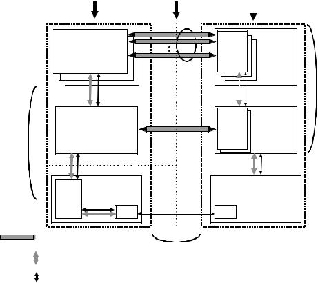
Figure 5-9 shows a more detailed view of Figure 5-2. The complete definition of the actual communication flows of Figure 5-2 supports the logical device and function layer communication flows. These actual communication flows cross several interface boundaries. Chapters 6 through 8 describe the mechanical, electrical, and protocol interface definitions of the USB “wire.” Chapter 9 describes the USB device programming interface that allows a USB device to be manipulated from the host side of the wire.
Chapter 10 describes two host side software interfaces:
•Host Controller Driver (HCD): The software interface between the USB Host Controller and USB System Software. This interface allows a range of Host Controller implementations without requiring all host software to be dependent on any particular implementation. One USB Driver can support different Host Controllers without requiring specific knowledge of a Host Controller implementation. A Host Controller implementer provides an HCD implementation that supports the Host Controller.
•USB Driver (USBD): The interface between the USB System Software and the client software. This interface provides clients with convenient functions for manipulating USB devices.
31
Universal Serial Bus Specification Revision 2.0
Host |
Interconnect |
Physical Device |
||
|
|
|
|
|
|
|
|
|
|
Client SW |
Function |
|
a collection of |
||
Interface x |
||
manages an interface |
interfaces |
|
Pipe Bundle |
|
|
to an interface |
|
Buffers |
No USB |
Interface- |
No USB |
|
Format |
specific |
Format |
|
|
|
USB Logical |
USB System SW |
|
Endpoint |
Device |
|
|
||
manages devices |
|
Zero |
a collection of |
Default Pipe |
|
||
|
endpoints |
||
|
to Endpoint Zero |
|
|
USB Host
(Chapter 10)
Transfers |
USB |
Data Per |
USB |
|
Framed |
Endpoint |
Framed |
|
Data |
|
Data |
|
USB Bus |
USB Bus |
Host |
Interface |
Interface |
USB Framed |
|
|
Controller |
|
|
|
Data |
|
|
SIE |
SIE |
|
Transactions |
USB Wire |
Pipe: represents connection abstraction between two horizontal entities
Mechanical,
Data transport mechanism |
Electrical, |
Protocol
USB-relevant format of transported data
(Chapter 6, 7, 8)
USB Device
(Chapter 9)
Figure 5-9. USB Host/Device Detailed View
A USB logical device appears to the USB system as a collection of endpoints. Endpoints are grouped into endpoint sets that implement an interface. Interfaces are views to the function. The USB System Software manages the device using the Default Control Pipe. Client software manages an interface using pipe bundles (associated with an endpoint set). Client software requests that data be moved across the USB between a buffer on the host and an endpoint on the USB device. The Host Controller (or USB device, depending on transfer direction) packetizes the data to move it over the USB. The Host Controller also coordinates when bus access is used to move the packet of data over the USB.
32