

usb_2.0_english
.pdfUniversal Serial Bus Specification Revision 2.0
6.5 Connector Mechanica l Configuration and Material Requirements
The USB Icon is used to identify USB plugs and the receptacles. Figure 6-5 illustrates the USB Icon.
|
|
All dimensions are ± 5% |
||
|
|
|
L |
|
|
|
Dia:1.33 L |
0.33 L |
|
|
Dia:1.67 L |
|
|
|
|
|
Dia:L |
|
L |
1.50 L |
|
|
Dia:L |
0.33 L |
|
|
|
|
L |
|
|
|
|
0.5 L |
1.50 L |
|
Dia:L |
Dia:L |
L |
|
|
|
|
|
|
|
|
|
L |
|
|
Dia:1.33 L |
L |
|
|
1.67 L |
|
0.33 L |
|
|
|
|
|
|
|
2.33 L |
|
|
|
|
3.75 L |
|
|
|
|
5.00 L |
|
|
|
|
5.17 L |
|
|
|
|
6.25 L |
|
|
|
|
8.00 L |
|
|
|
Figure 6-5. USB Icon
6.5.1 USB Icon Location
The USB Icon is embossed, in a recessed area, on the topside of the USB plug. This provides easy user recognition and facilitates alignment during the mating process. The USB Icon and Manufacturer’s logo should not project beyond the overmold surface. The USB Icon is required, while the Manufacturer’s logo is recommended, for both Series “A” and “B” plug assemblies. The USB Icon is also located adjacent to each receptacle. Receptacles should be oriented to allow the Icon on the plug to be visible during the mating process. Figure 6-6 illustrates the typical plug orientation.
Top View
A
Optional Top
"Locator Detail"
|
A Locator |
|
|
|
Height |
|
|
|
Approximately |
|
|
|
0.6mm |
|
|
|
(0.024") |
|
|
|
Manufacturer’s |
1 |
|
Engraved USB |
Engraved Logo |
2 |
|
|
|||
Icon |
|
||
|
|
||
|
Locator Width |
3 |
|
|
|
||
|
Approximately |
4 |
|
|
0.5mm |
||
Overmolding |
|
||
(0.020") |
|
||
|
|
||
0.6mm (0.024") |
0.6mm (0.024") Max |
|
|
Max |
Manufacturer’s |
Optional Top |
|
USB Icon |
Logo |
||
"Locator Detail" |
|||
Engraving Recess |
Engraving Recess |
Section A - A
(Plug Cross-Section)
Figure 6-6. Typical USB Plug Orientation
93
Universal Serial Bus Specification Revision 2.0
6.5.2 USB Connector Termination Data
Table 6-1 provides the standardized contact terminating assignments by number and electrical value for Series “A” and Series “B” connectors.
Table 6-1. USB Connector Termination Assignment
Contact |
Signal Name |
Typical Wiring |
|
Number |
Assignment |
||
|
|||
|
|
|
|
1 |
VBUS |
Red |
|
|
|
|
|
2 |
D- |
White |
|
|
|
|
|
3 |
D+ |
Green |
|
|
|
|
|
4 |
GND |
Black |
|
|
|
|
|
Shell |
Shield |
Drain Wire |
|
|
|
|
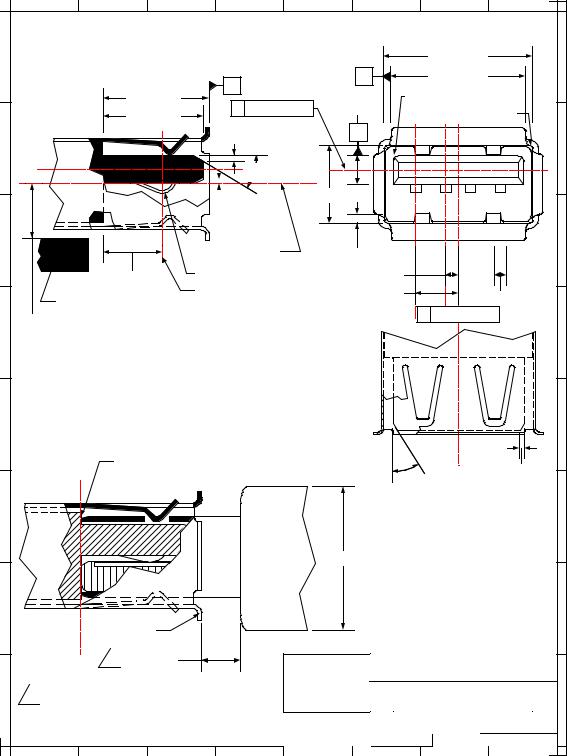
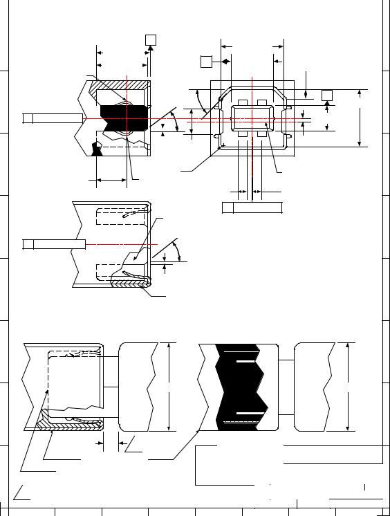
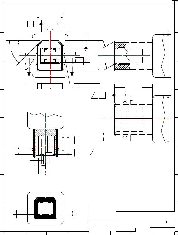
6.5.3 Series “A” and Series “B” Receptacles
Electrical and mechanical interface configuration data for Series "A" and Series "B" receptacles are shown in Figure 6-7 and Figure 6-8. Also, refer to Figure 6-12, Figure 6-13, and Figure 6-14 at the end of this chapter for typical PCB receptacle layouts.
94
Universal Serial Bus Specification Revision 2.0
H
G
F
E
D
C
B
A
8 |
7 |
6 |
5 |
4 |
3 |
2 |
1 |
|
USB Series "A" Receptacle Interface |
|
|
||||
|
|
|
|
|
|
12.50 ± 0.10 |
|
|
|
|
A |
|
C |
11.10 ± 0.10 |
|
|
8.88 ± 0.20 |
|
|
|
|
|
|
|
|
B Center Line |
|
R 0.64 ± 0.13 (Typical) |
|||
|
8.38 ± 0.08 |
|
|
1.84 ± 0.05 |
|
|
|
|
|
|
|
R 0.32 ± 0.13 (Typical) |
|||
|
|
|
0.50 ± 0.10 |
|
B |
|
|
|
|
|
300 ± 20 (2) |
|
1 |
2 3 |
4 |
|
|
|
5.12 ± 0.10 |
|
|
||
|
|
|
0.38 ± 0.13 |
|
|
|
|
|
|
|
Center Line of 5.12 |
|
0.64 ± 0.13 (8) |
|
|
|
4.98 ± 0.25 |
|
Receptacle Contact |
|
1.00 ± 0.05 (2) |
|
|
|
Printed Circuit Board |
|
Contact Point |
|
3.50 ± 0.05 (2) |
1.00 ± 0.05 (4) |
|
|
|
|
|
|
|||
|
|
|
|
|
C Center Line |
|
|
4.13 REF |
|
|
|
|
|
||
|
|
|
|
|
|
||
All dimensions are in millimeters (mm) unless otherwise noted.
USB Series "A" Receptacle and Plug
Mating Features
Fully Mated Series "A"
|
Receptacle and Plug |
|
|
|
|
0.50 ± 0.10 (2) |
||
|
|
|
|
|
|
|
||
|
|
|
|
|
|
300 ± 20 (2) |
|
|
|
|
|
|
Boot |
|
|
|
|
|
|
|
|
Overmold |
8.0 MAX |
|
|
|
|
|
|
|
|
|
|
|
|
|
Receptacle Flange |
|
|
|
|
|
|
|
|
1 |
2.67 MIN |
|
|
Interface and Mating Drawing |
|||
|
|
|
|
|
||||
1 |
Allow a minimum spacing of 2.67mm between |
|
Series "A" Receptacle |
|||||
the face of the receptacle and the plug |
|
|
||||||
|
|
|
|
|
|
|
||
|
overmold boot. |
|
|
|
SIZE |
DATE |
DRAWING NUMBER |
REV |
|
|
|
|
|
A |
2/98 |
N/A |
C |
|
|
|
|
|
SCALE: N/A |
SHEET |
1 of 1 |
|
8 |
7 |
6 |
5 |
4 |
3 |
|
2 |
1 |
H
G
F
E
D
C
B
A
Figure 6-7. USB Series "A" Receptacle Interface and Mating Drawing
95
Universal Serial Bus Specification Revision 2.0
8 |
7 |
6 |
5 |
4 |
3 |
2 |
1 |
USB Series "B" Receptacle Interface
H |
|
A |
|
8.45 + 0.10 |
|
H |
|
|
|
8.88 + 0.20 |
|
|
|
||
|
|
|
5.60 + 0.10 |
|
|
||
|
|
8.38 + 0.08 |
C |
1.63 + 0.05 (2) |
|
||
|
|
|
|
|
|
||
Receptacle Contact |
450 + 0.50 (2) |
|
|
|
|
||
|
|
|
|
|
|
||
|
|
300 + |
20 (4) |
|
|
B |
|
G |
|
2 |
1 |
7.78 + 0.10 |
G |
||
|
|
|
|
|
|
||
B |
Center Line |
|
|
|
|
3.18 + 0.05 |
|
|
|
|
|
3 |
4 |
0.80 + 0.08 |
|
|
|
3.67 + 0.08 |
|
|
|
||
|
|
|
|
|
|
||
|
|
0.38 + 0.13 (4) |
|
|
|
|
|
F |
|
R 0.38 (6) |
|
|
3.67 Center Line |
F |
|
|
|
|
|
|
|||
|
4.98 + 0.25 |
Contact Point |
|
|
|
||
|
|
|
|
|
|||
|
|
|
1.00 + 0.05 (4) |
|
|
1.25 + 0.10 (4) |
|
|
|
|
C |
Center Line |
|
|
|
|
|
|
|
Receptacle Housing |
|
|
|
|
|
|
E |
|
|
|
300 + 20 (2) |
|
|
|
|
|
E |
B |
Center Line |
|
|
|
|
|
|
|
|
|
|
|
|
|
|
|
All dimensions are in millimeters (mm) |
||||
|
|
|
|
|
|
unless otherwise noted. |
|
|
||
|
|
|
|
0.50 + 0.10 (2) |
|
|
|
|
|
|
D |
|
|
|
Receptacle Shell |
|
|
|
|
D |
|
|
|
|
|
|
|
|
|
|
||
|
USB Series "B" Receptacle and Plug Mating Features |
|
|
|||||||
C |
|
|
Boot |
|
|
|
|
Boot |
|
C |
|
|
|
|
|
|
|
|
|
||
|
|
|
Overmold |
10.5 MAX |
|
|
|
Overmold |
11.5 MAX |
|
|
|
|
|
|
|
|
|
|||
B |
|
|
|
|
|
|
|
|
|
B |
|
2.67 MIN |
1 |
|
|
|
|
|
|
|
|
|
|
|
|
|
Interface and Mating Drawing |
|||||
|
|
Receptacle Shell |
|
|
||||||
|
|
|
|
|
|
|
|
|
||
|
Fully Mated Plug and Receptacle |
|
USB Series "B" Receptacle |
|||||||
A |
|
|
|
|
|
|
|
|
|
A |
1 |
Allow a minimum spacing of 2.67mm between the |
|
SIZE |
DATE |
DRAWING NUMBER |
REV |
||||
face of the receptacle and the plug overmold boot. |
|
A |
2/98 |
|
N/A |
C |
||||
|
|
SCALE: N/A |
|
SHEET |
1 of 1 |
|||||
|
|
|
|
|
|
|
||||
8 |
7 |
|
6 |
5 |
4 |
3 |
|
2 |
|
1 |
Figure 6-8. USB Series "B" Receptacle Interface and Mating Drawing
96
Universal Serial Bus Specification Revision 2.0
6.5.3.1 Receptacle Injection M olded Thermoplastic Insulator Material
Minimum UL 94-V0 rated, thirty percent (30%) glass-filled polybutylene terephthalate (PBT) or polyethylene terephthalate (PET) or better.
Typical Colors: Black, gray, and natural.
Flammability Characteristics: UL 94-V0 rated.
Flame Retardant Package must meet or exceed the requirements for UL, CSA, VDE, etc.
Oxygen Index (LOI): Greater than 21%. ASTM D 2863.
6.5.3.2 Receptacle Shell Mate rials
Substrate Material: 0.30 + 0.05 mm phosphor bronze, nickel silver, or other copper based high strength materials.
Plating:
1.Underplate: Optional. Minimum 1.00 micrometers (40 microinches) nickel. In addition, manufacturer may use a copper underplate beneath the nickel.
2.Outside: Minimum 2.5 micrometers (100 microinches) bright tin or bright tin-lead.
6.5.3.3Receptacle Contact M aterials
Substrate Material: 0.30 + 0.05 mm minimum half-hard phosphor bronze or other high strength copper based material.
Plating: Contacts are to be selectively plated.
A.Option I
1.Underplate: Minimum 1.25 micrometers (50 microinches) nickel. Copper over base material is optional.
2.Mating Area: Minimum 0.05 micrometers (2 microinches) gold over a minimum of
0.70micrometers (28 microinches) palladium.
3.Solder Tails: Minimum 3.8 micrometers (150 microinches) bright tin-lead over the underplate.
B.Option II
1.Underplate: Minimum 1.25 micrometers (50 microinches) nickel. Copper over base material is optional.
2.Mating Area: Minimum 0.05 micrometers (2 microinches) gold over a minimum of
0.75micrometers (30 microinches) palladium-nickel.
3.Solder Tails: Minimum 3.8 micrometers (150 microinches) bright tin-lead over the underplate.
C.Option III
1.Underplate: Minimum 1.25 micrometers (50 microinches) nickel. Copper over base material is optional.
2.Mating Area: Minimum 0.75 micrometers (30 microinches) gold.
3.Solder Tails: Minimum 3.8 micrometers (150 microinches) bright tin-lead over the underplate.
97
Universal Serial Bus Specification Revision 2.0
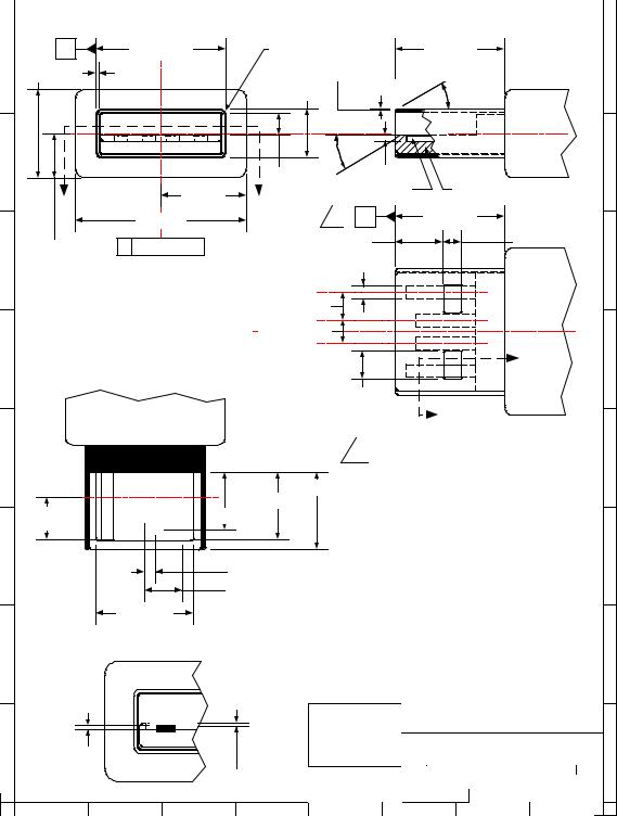
6.5.4 Series “A” and Series “B” Plugs
Electrical and mechanical interface configuration data for Series "A" and Series "B" plugs are shown in Figure 6-9 and Figure 6-10.
98
Universal Serial Bus Specification Revision 2.0
8 |
7 |
6 |
5 |
4 |
3 |
2 |
1 |
B |
|
12.00 ± 0.10 |
|
R 0.64 + 0.13 Typical |
11.75 MIN |
|
||
H 8.0 MAX |
0.315 ± 0.03 Typical |
0.15 ± 0.10 Typical |
300 ± 20 Typical |
H |
||||
|
|
|
|
|
4.50 ± 0.10 |
|
|
|
|
|
|
|
|
300 ± 20 |
|
|
|
|
4 |
3 |
2 |
1 |
|
|
|
|
G |
|
|
|
|
1.95 ± 0.05 |
0.38 ± 0.13 |
|
G |
|
|
|
|
|
|
|
||
A |
|
8.0 MAX |
A |
Plug Contact |
UL 94-V0 Plug Housing |
|
|
A |
11.75 MIN |
||
|
|
16.0 MAX |
1 |
||
4.0 MAX |
B |
Center Line |
5.16 ± 0.10 |
2.00 ± 0.13 (4) |
|
|
|
|
|||
F |
|
|
1.00 ± 0.05 (4) |
F |
|
|
|
2.50 ± 0.05 (2) |
|
Boot |
|
|
Section A - A |
2.00 ± 0.05 (2) |
|
Overmold |
|
|
B Center Line |
|
|
|
|
E |
|
|
B |
|
E |
|
|
|
|
||
|
|
2.50 ± 0.13 (4) |
|
|
|
|
Overmold Boot |
|
B |
|
|
|
|
|
|
|
|
|
|
1 |
Overall connector and cable assembly |
|
|
D |
|
length is measured from Datum ’A’ of |
D |
||
|
|
||||
|
|
the Series "A" Plug to Datum ’A’ of the |
|||
|
|
8.65 ± 0.19 |
|
||
|
|
Series "B" Plug or to the blunt end |
|
||
|
|
7.41 ± 0.31 |
termination. |
|
|
|
|
|
|
|
|
4.2 MIN |
6.41 ± 0.31 |
GOLD PLATE AREA |
All dimensions are in millimeters (mm) |
|
|
|
unless otherwise noted. |
C |
C |
|
1.0 ± 0.05 (2) |
|
3.5 ± 0.05 (2) |
|
9.70 ± 0.13 |
Section B - B
B |
B |
|
|
|
|
|
|
|
Interface Drawing |
|
|
A |
0.16 ± 0.15 |
|
|
|
|
|
USB Series "A" Plug |
||
|
|
|
|
|
|
|
|
A |
|
|
|
|
|
0.13 ± 0.13 |
|
SIZE |
DATE |
DRAWING NUMBER |
REV |
|
|
|
|
|
A |
2/98 |
N/A |
C |
|
|
|
|
|
|
|
||||
|
|
|
|
|
|
SCALE: N/A |
SHEET |
1 of 1 |
|
|
8 |
7 |
6 |
5 |
4 |
3 |
|
2 |
1 |
Figure 6-9. USB Series "A" Plug Interface Drawing
99
Universal Serial Bus Specification Revision 2.0
H
G
F
E
D
C
8 |
7 |
6 |
5 |
4 |
3 |
2 |
1 |
|
8.00 ± 0.10 |
|
|
|
|
C |
|
|
5.83 ± 0.10 |
|
|
|
|
|
0.38 MAX |
|
10.5 MAX |
1.46 ± 0.10 |
|
|
B |
300 ± 20 Typical |
|
450 ± 0.50 (2) |
1 |
2 |
|
|
Boot |
|
|
|
0.80 ± 0.05 |
|
Overmold |
|
|
|
3.29 ± 0.05 |
|
|
|
4 |
3 |
7.26 ± 0.10 |
|
|
|
|
|
|
||
Center Line |
|
|
|
|
|
of 2.85 |
|
|
|
300 ± 20 (2) |
|
A |
|
|
A |
|
|
2.85 ± 0.13 (2) |
C Center Line |
B Center Line |
11.75 MIN |
||
|
|
|
|
|
|
|
|
|
|
|
11.5 MAX |
|
|
|
1 |
A |
3.70 ± 0.13 |
Section A - A
|
6.41 ± 0.31 |
4.20 MIN |
|
Gold Plate Area |
8.65 ± 0.19 |
|
|
1.16 MAX |
7.41 ± 0.31 |
1.25 ± 0.10 (4) |
|
 B
B
|
|
|
|
|
|
|
|
|
|
|
|
|
|
|
|
|
|
|
|
|
|
|
|
|
|
|
|
|
|
|
|
|
|
|
|
|
|
|
|
|
|
|
|
|
Boot |
|
|
|
|
|
|
|
|
|
|
|
|
|
|
|
|
|
|
|
|
|
|
|
|
|
|
|
|
|
|
|
|
|
|
|
|
|
|
|
|
|
|
|
|
|
|
||
|
|
|
|
|
|
|
|
|
|
|
|
|
|
|
|
|
|
|
|
|
|
|
|
|
|
|
|
|
|
|
|
|
|
|
|
|
|
|
|
|
|
|
|
|
||
|
|
|
|
|
|
|
|
|
|
|
|
|
|
|
|
|
|
|
|
|
|
|
|
|
|
|
|
|
|
|
|
|
|
|
|
|
|
|
|
|
|
|
|
|
|
|
|
|
|
|
|
|
|
|
|
|
|
|
|
|
|
|
|
|
|
|
|
|
|
|
|
|
|
|
|
|
|
|
|
|
|
|
|
|
|
|
|
|
|
|
|
|
|
|
|
|
|
|
|
|
|
|
|
|
|
|
|
|
|
|
|
|
|
|
|
|
|
|
|
|
|
|
|
Overmold |
||||||||||||||||
|
|
|
|
|
|
|
|
|
|
|
|
|
|
|
|
|
|
|
|
|
|
|
|
|
|
|
|
|
|
|
|
|
|
|
|
|
|
|
|
|
|
|
|
|
||
0.25 ± 0.05 |
|
|
|
|
|
|
|
|
|
|
|
|
|
|
|
|
|
|
|
|
|
|
|
|
|
|
|
|
|
|
|
|
|
|
||||||||||||
|
|
|
|
|
|
|
|
|
|
|
|
|
|
|
|
|
|
|
|
|
|
|
|
|
|
|
|
|
|
|
|
|
|
|
|
|||||||||||
|
|
|
|
|
|
|
|
|
|
|
|
|
|
|
|
|
|
|
|
|
|
|
|
|
|
|
|
|
|
|
|
|
|
|
|
|
|
|
|
|
|
|
|
|
|
|
|
|
|
|
|
|
|
|
|
|
|
|
|
|
|
|
|
|
|
|
|
|
|
|
|
|
|
|
|
|
|
|
|
|
|
|
|
|
|
|
|
|
|
|
|
|
|
|
|
|
|
|
|
|
|
|
|
|
|
|
|
|
|
|
|
|
|
|
|
|
|
|
|
|
|
|
|
|
|
|
|
|
|
|
|
|
|
|
|
|
|
|
|
|

 B
B
Overall connector and cable assembly length
1is measured from Datum 'A' of the Series "B" Plug to Datum 'A' of the Series "A" Plug or the blunt end termination.


 4.67 ± 0.10
H
G
F
E
D
C
|
|
|
All dimensions are in millimeters (mm) |
|
C |
Center Line |
|||
unless otherwise noted. |
||||
|
|
|
||
|
|
|
||
|
Section B - B |
B |
B |
0.16 ± 0.15 |
|
|
0.13 ± 0.13 |
|
|
Interface Drawing |
|
|
Typical |
|
|
Typical |
|
|
|
||
A |
|
|
|
|
USB Series "B" Plug |
|||
|
|
|
|
|
|
|
A |
|
|
|
|
|
|
SIZE |
DATE |
DRAWING NUMBER |
REV |
|
|
|
|
|
A |
2/98 |
N/A |
C |
|
|
|
|
|
SCALE: |
N/A |
SHEET |
1 of 1 |
8 |
7 |
6 |
5 |
4 |
3 |
|
2 |
1 |
Figure 6-10. USB Series “B” Plug Interface Drawing
100
Universal Serial Bus Specification Revision 2.0
6.5.4.1 Plug Injection Molded Thermoplastic Insulator Material
Minimum UL 94-V0 rated, thirty percent (30%) glass-filled polybutylene terephthalate (PBT) or polyethylene terephthalate (PET) or better.
Typical Colors: Black, gray, and natural.
Flammability Characteristics: UL 94-V0 rated.
Flame Retardant Package must meet or exceed the requirements for UL, CSA, and VDE.
Oxygen Index (LOI): 21%. ASTM D 2863.
6.5.4.2 Plug Shell Materials
Substrate Material: 0.30 + 0.05 mm phosphor bronze, nickel silver, or other suitable material.
Plating:
A.Underplate: Optional. Minimum 1.00 micrometers (40 microinches) nickel. In addition, manufacturer may use a copper underplate beneath the nickel.
B.Outside: Minimum 2.5 micrometers (100 microinches) bright tin or bright tin-lead.
6.5.4.3 Plug (Male) Contact M aterials
Substrate Material: 0.30 + 0.05 mm half-hard phosphor bronze.
Plating: Contacts are to be selectively plated.
A.Option I
1.Underplate: Minimum 1.25 micrometers (50 microinches) nickel. Copper over base material is optional.
2.Mating Area: Minimum 0.05 micrometers (2 microinches) gold over a minimum of
0.70micrometers (28 microinches) palladium.
3.Solder Tails: Minimum 3.8 micrometers (150 microinches) bright tin-lead over the underplate.
B.Option II
1.Underplate: Minimum 1.25 micrometers (50 microinches) nickel. Copper over base material is optional.
2.Mating Area: Minimum 0.05 micrometers (2 microinches) gold over a minimum of
0.75micrometers (30 microinches) palladium-nickel.
3.Wire Crimp/Solder Tails: Minimum 3.8 micrometers (150 microinches) bright tin-lead over the underplate.
C.Option III
1.Underplate: Minimum 1.25 micrometers (50 microinches) nickel. Copper over base material is optional.
2.Mating Area: Minimum 0.75 micrometers (30 microinches) gold.
3.Solder Tails: Minimum 3.8 micrometers (150 microinches) bright tin-lead over the underplate.
101
Universal Serial Bus Specification Revision 2.0
6.6 Cable Mechanical Con figuration and Material Requirements
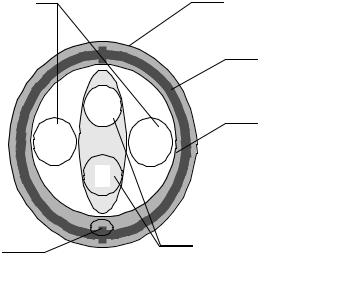
High-/full-speed and low-speed cables differ in data conductor arrangement and shielding. Low-speed recommends, but does not require, use of a cable with twisted data conductors. Low speed recommends, but does not require, use of a cable with a braided outer shield. Figure 6-11 shows the typical high-/full- speed cable construction.
on-Twisted Power Pair: |
Polyvinyl Chloride (PVC) Jacket |
|
Red: |
VBUS |
|
Black: |
Power Ground |
|
|
|
|
Outer Shield > 65% Interwoven
Tinned Copper Braid
W
R B
G
28 AWG Tinned
Copper Drain Wire
Inner Shield Aluminum
Metallized Polyester
Twisted Signaling Pair:
White: D-
Green: D+
Figure 6-11. Typical High-/full-speed Cable Construction
6.6.1 Description
High-/full-speed cable consists of one 28 to 20 AWG non-twisted power pair and one 28 AWG twisted data pair with an aluminum metallized polyester inner shield, 28 AWG stranded tinned copper drain wire,
> 65% tinned copper wire interwoven (braided) outer shield, and PVC outer jacket.
Low-speed cable consists of one 28 to 20 AWG non-twisted power pair and one 28 AWG data pair (a twist is recommended) with an aluminum metallized polyester inner shield, 28 AWG stranded tinned copper drain wire and PVC outer jacket. A > 65% tinned copper wire interwoven (braided) outer shield is recommended.
102