usb_2.0_english
.pdfUniversal Serial Bus Specification Revision 2.0
7.1.7.5 Reset Signaling
A hub signals reset to a downstream port by driving an extended SE0 at the port. After the reset is removed, the device will be in the Default state (refer to Section 9.1).
The reset signaling can be generated on any Hub or Host Controller port by request from the USB System Software. The reset signaling must be driven for a minimum of 10ms (TDRST). After the reset, the hub port will transition to the Enabled state (refer to Section 11.5).
As an additional requirement, Host Controllers and the USB System Software must ensure that resets issued to the root ports drive reset long enough to overwhelm any concurrent resume attempts by downstream devices. It is required that resets from root ports have a duration of at least 50 ms (TDRSTR). It is not required that this be 50 ms of continuous Reset signaling. However, if the reset is not continuous, the interval(s) between reset signaling must be less than 3 ms (TRHRSI), and the duration of each SE0 assertion must be at least 10 ms (TDRST).
A device operating in low-/full-speed mode that sees an SE0 on its upstream facing port for more than 2.5 s (TDETRST) may treat that signal as a reset. The reset must have taken effect before the reset signaling ends.
Hubs will propagate traffic to a newly reset port after the port is in the Enabled state. The device attached to this port must recognize this bus activity and keep from going into the Suspend state.
Hubs must be able to accept all hub requests and devices must be able to accept a SetAddress() request (refer to Section 11.24.2 and Section 9.4 respectively) after the reset recovery time 10 ms (TRSTRCY) after the reset is removed. Failure to accept this request may cause the device not to be recognized by the USB system software. Hubs and devices must complete commands within the times specified in Chapter 9 and Chapter 11.
Reset must wake a device from the Suspend state.
It is required that a high-speed capable device can be reset while in the Powered, Default, Address, Configured, or Suspended states shown in Figure 9-1. The reset signaling is compatible with low-/full-speed reset. This means that a hub must successfully reset any device (even USB 1.X devices), and a device must be successfully reset by any hub (even USB1.X hubs).
If, and only if, a high-speed capable device is reset by a high-speed capable hub which is not high-speed disallowed, both hub and device must be operating in the default state in high-speed signaling mode at the end of reset. The hub port status register must indicate that the port is in high-speed signaling mode. This requirement is met by having such a device and such a hub engage in a low level protocol during the reset signaling time. The protocol is defined in such a way that USB 1.X devices will not be disrupted from their normal reset behaviors.
Note: Because the downstream facing port will not be in Transmit state during the Reset Protocol, high-speed Chirp signaling levels will not provoke disconnect detection. (Refer to Section 7.1.7.3 and Section 11.5.1.7.)
Reset Protocol for high-speed capable hubs and devices
1.The hub checks to make sure the attached device is not low-speed. (A low-speed device is not allowed to support high-speed operation. If the hub determines that it is attached to a low-speed device, it does not conduct the following high-speed detection protocol during reset.)
2.The hub drives SE0. In this description of the Reset Protocol and High-speed Detection Handshake, the start of SE0 is referred to as time T0.
153
Universal Serial Bus Specification Revision 2.0
3.The device detects assertion of SE0.
a)If the device is being reset from suspend, then the device begins a high-speed detection handshake after the detection of SE0 for no less than 2.5 µs (T FILTSE0). Since a suspended device will generally have its clock oscillator disabled, the detection of SE0 will cause the oscillator to be restarted. The clock must be useable (although not necessarily settled to 500 ppm accuracy) in time to detect the high-speed hub chirp as described in Step 8.
b)If the device is being reset from a non-suspended full-speed state, then the device begins a high-speed detection handshake after the detection of SE0 for no less than 2.5 µs and no more than 3.0 ms
(TWTRSTFS).
c)If the device is being reset from a non-suspended high-speed state, then the device must wait no less than 3.0 ms and no more than 3.125 ms (TWTREV) before reverting to full-speed. Reversion to fullspeed is accomplished by removing the high-speed termination and reconnecting the D+ pull-up
resistor. The device samples the bus state, and checks for SE0 (reset as opposed to suspend), no less than 100 s and no more than 875 s (TWTRSTHS) after starting reversion to full-speed. If SE0 (reset) is
detected, then the device begins a high-speed detection handshake.
High-speed Detection Handshake (not performed if low-speed device detected by hub):
Note: In the following handshake, both the hub and device are required to detect Chirp J’s and K’s of specified minimum durations. It is strongly recommended that “gaps” in these Chirp signals as short as 16 high-speed bit times should restart the duration timers.
4.The high-speed device leaves the D+ pull-up resistor connected, leaves the high-speed terminations disabled, and drives the high-speed signaling current into the D- line. This creates a Chirp K on the bus. The device chirp must last no less than 1.0 ms (TUCH) and must end no more than 7.0 ms (TUCHEND) after high-speed Reset time T0.
5. The hub must detect the device chirp after it has seen assertion of the Chirp K for no less than 2.5 µs (T FILT). If the hub does not detect a device chirp, it must continue the assertion of SE0 until the end of reset.
6.No more than 100 µs (T WTDCH) after the bus leaves the Chirp K state, the hub must begin to send an alternating sequence of Chirp K’s and Chirp J’s. There must be no Idle states on the bus between the J’s and K’s. This sequence must continue until a time (TDCHSE0) no more than 500 µs before and no less than 100 µs before the end of Reset. (This will guarantee that the bus remains active, preventing the device from entering the high-speed Suspend state.) Each individual Chirp K and Chirp J must last no less than 40 µs and no more than 60 µs (T DCHBIT).
7.After completing the hub chirp sequence, the hub asserts SE0 until end of Reset. At the end of reset, the hub must transition to the high-speed Enabled state without causing any transitions on the data lines.
8.After the device completes its chirp, it looks for the high-speed hub chirp. At a minimum, the device is required to see the sequence Chirp K-J-K-J-K-J in order to detect a valid hub chirp. Each individual Chirp K and Chirp J must be detected for no less than 2.5 µs (T FILT).
a)If the device detects the sequence Chirp K-J-K-J-K-J, then no more than 500 µs (T WTHS) after detection, the device is required to disconnect the D+ pull-up resistor, enable the high-speed terminations, and enter the high-speed Default state.
b)If the device has not detected the sequence Chirp K-J-K-J-K-J by a time no less than 1.0 ms and no more than 2.5 ms (TWTFS) after completing its own chirp, then the device is required to revert to the full-speed Default state and wait for the end of Reset.
7.1.7.6 Suspending
All devices must support the Suspend state. Devices can go into the Suspend state from any powered state. They begin the transition to the Suspend state after they see a constant Idle state on their upstream facing bus lines for more than 3.0 ms. The device must actually be suspended, drawing only suspend current from the bus after no more than 10 ms of bus inactivity on all its ports. Any bus activity on the upstream facing port will keep
154
Universal Serial Bus Specification Revision 2.0
a device out of the Suspend state. In the absence of any other bus traffic, the SOF token (refer to Section 8.4.3) will occur once per (micro)frame to keep full-/high-speed devices from suspending. In the absence of any lowspeed traffic, low-speed devices will see at least one keep-alive (defined in Table 7-2) in every frame in which an SOF occurs, which keeps them from suspending. Hubs generate this keep-alive as described in
Section 11.8.4.1.
While in the Suspend state, a device must continue to provide power to its D+ (full-/high-speed) or D- (lowspeed) pull-up resistor to maintain an idle so that the upstream hub can maintain the correct connectivity status for the device.
Additional Requirements for High-speed Capable Devices
From the perspective of a device operating in high-speed mode, a Reset and a Suspend are initially indistinguishable, so the first part of the device response is the same as for a Reset. When a device operating in high-speed mode detects that the data lines have been in the high-speed Idle state for at least 3.0 ms, it must revert to the full-speed configuration no later than 3.125 ms (TWTREV) after the start of the idle state. Reversion to full-speed is accomplished by disconnecting its termination resistors and reconnecting its D+ pull-up resistor. No earlier than 100 s and no later than 875 s (TWTRSTHS) after reverting to full-speed, the device must sample the state of the line. If the state is a full-speed J, the device continues with the Suspend process. (SE0 would have indicated that the downstream facing port was driving reset, and the device would have gone into the “High-speed Detection Handshake” as described in Section 7.1.7.5.)
A device or downstream facing port which is suspended from high-speed operation actually transitions to fullspeed signaling during the suspend process, but is required to remember that it was operating in high-speed mode when suspended. When the resume occurs, the device or downstream facing transceiver must revert to high-speed as discussed in Section 7.1.7.7 without the need for a reset.
7.1.7.6.1 Global Suspend
Global suspend is used when no communication is desired anywhere on the bus and the entire bus is placed in the Suspend state. The host signals the start of global suspend by ceasing all its transmissions (including the SOF token). As each device on the bus recognizes that the bus is in the Idle state for the appropriate length of time, it goes into the Suspend state.
After 3.0 ms of continuous idle state, a downstream facing transceiver operating in high-speed must revert to the full-speed idle configuration (high-speed terminations disabled), but it does not enable full-speed disconnect detection until 1.0 ms later. This is to make sure that the device has returned to the full-speed Idle state prior to the enabling of full-speed disconnect detection, thereby preventing an unintended disconnect detection. After reenabling the full-speed disconnect detection mechanism, the hub continues with the suspend process.
7.1.7.6.2 Selective Suspend
Segments of the bus can be selectively suspended by sending the command SetPortFeature(PORT_SUSPEND) to the hub port to which that segment is attached. The suspended port will block activity to the suspended bus segment, and devices on that segment will go into the Suspend state after the appropriate delay as described above.
When a downstream facing port operating in high-speed mode receives the SetPortFeature(PORT_SUSPEND) command, the port immediately reverts to the full-speed Idle state and blocks any activity to the suspend segment. Full-speed disconnect detection is disabled until the port has been in full-speed idle for 4.0 ms. This prevents an unintended disconnect detection. After re-enabling the full-speed disconnect detection mechanism, the hub continues with the suspend process.
Section 11.5 describes the port Suspend state and its interaction with the port state machine. Suspend is further described in Section 11.9.
155
Universal Serial Bus Specification Revision 2.0
7.1.7.7 Resume
If a device is in the Suspend state, its operation is resumed when any non-idle signaling is received on its upstream facing port. Additionally, the device can signal the system to resume operation if its remote wakeup capability has been enabled by the USB System Software. Resume signaling is used by the host or a device to bring a suspended bus segment back to the active condition. Hubs play an important role in the propagation and generation of resume signaling. The following description is an outline of a general global resume sequence. A complete description of the resume sequence, the special cases caused by selective suspend, and the role of the hub are given in Section 11.9.
The host may signal resume (TDRSMDN) at any time. It must send the resume signaling for at least 20 ms and then end the resume signaling in one of two ways, depending on the speed at which its port was operating when it was suspended. If the port was in low-/full-speed when suspended, the resume signaling must be ended with a standard, low-speed EOP (two low-speed bit times of SE0 followed by a J). If the port was operating in highspeed when it was suspended, the resume signaling must be ended with a transition to the high-speed idle state.
The 20 ms of resume signaling ensures that all devices in the network that are enabled to see the resume are awakened. The connectivity established by the resume signaling is torn down by the End of Resume, which prepares the hubs for normal operation. After resuming the bus, the host must begin sending bus traffic (at least the SOF token) within 3 ms of the start of the idle state to keep the system from going back into the Suspend state.
A device with remote wakeup capability may not generate resume signaling unless the bus has been continuously in the Idle state for 5 ms (TWTRSM). This allows the hubs to get into their Suspend state and prepare for propagating resume signaling. The remote wakeup device must hold the resume signaling for at least 1 ms but for no more than 15 ms (TDRSMUP). At the end of this period, the device stops driving the bus (puts its drivers into the high-impedance state and does not drive the bus to the J state).
If the hub upstream of a remote wakeup device is suspended, it will propagate the resume signaling to its upstream facing port and to all of its enabled downstream facing ports, including the port that originally signaled the resume. When a hub is propagating resume signaling from a downstream device, it may transition from the idle state to K with a risetime faster than is normally allowed. The hub must begin this rebroadcast (TURSM) of the resume signaling within 1 ms of receiving the original resume. The resume signal will propagate in this manner upstream until it reaches the host or a non-suspended hub (refer to Section 11.9), which will reflect the resume downstream and take control of resume timing. This hub is termed the controlling hub. Intermediate hubs (hubs between the resume initiator and the controlling hub) drive resume (TDRSMUP) on their upstream facing port for at least 1 ms during which time they also continue to drive resume on enabled downstream facing ports. An intermediate hub will stop driving resume on the upstream facing port and reverse the direction of connectivity from upstream to downstream within 15 ms after first asserting resume on its upstream facing port. When all intermediate hubs have reversed connectivity, resume is being driven from the controlling hub through all intermediate hubs and to all enabled ports. The controlling hub must rebroadcast the resume signaling within 1 ms (TURSM) and ensures that resume is signaled for at least 20 ms (TDRSMDN). The hub may then begin normal operation by terminating the resume process as described above.
The USB System Software must provide a 10 ms resume recovery time (TRSMRCY) during which it will not attempt to access any device connected to the affected (just-activated) bus segment.
Port connects and disconnects can also cause a hub to send a resume signal and awaken the system. These events will cause a hub to send a resume signal only if the hub has been enabled as a remote-wakeup source. Refer to Section 11.4.4 for more details.
Refer to Section 7.2.3 for a description of power control during suspend and resume.
If the hub port and device were operating in high-speed prior to suspend, they are required to "remember" that they were previously operating in high-speed, and they must transition back to high-speed operation, without arbitration, within two low-speed bit times of the K to SE0 transition. The inactivity timers must be started two low-speed bit times after the K to SE0 transition. Note that the transition from SE0 to J which would normally
156
Universal Serial Bus Specification Revision 2.0
occur at the end of full-speed resume signaling is omitted if the link was operating in high-speed at the time when it was suspended.
It is required that the host begin sending SOF’s in time to prevent the high-speed tree from suspending.
7.1.8 Data Encoding/Decoding
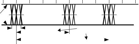
The USB employs NRZI data encoding when transmitting packets. In NRZI encoding, a “1” is represented by no change in level and a “0” is represented by a change in level. Figure 7-31 shows a data stream and the NRZI equivalent. The high level represents the J state on the data lines in this and subsequent figures showing NRZI encoding. A string of zeros causes the NRZI data to toggle each bit time. A string of ones causes long periods with no transitions in the data.
'DWD
15=,
,GOH
J
K ,GOH
Figure 7-31. NRZI Data Encoding
7.1.9 Bit Stuffing
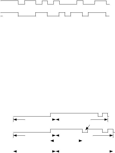
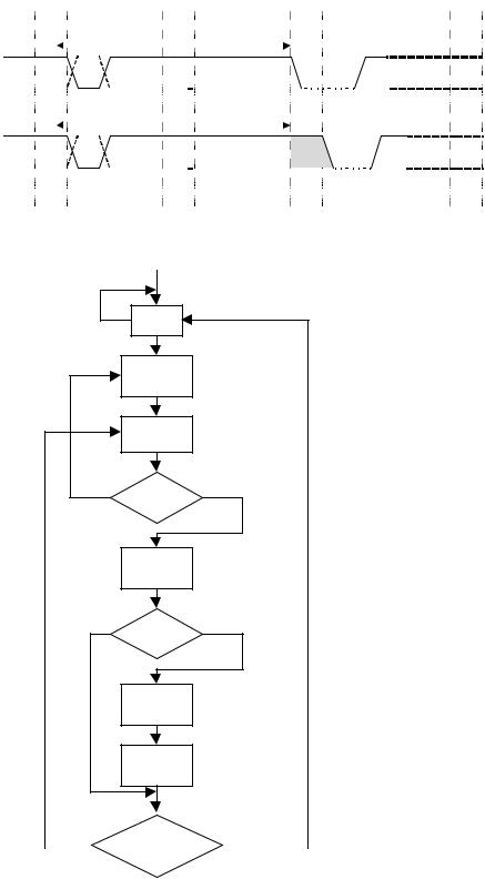
In order to ensure adequate signal transitions, bit stuffing is employed by the transmitting device when sending a packet on USB (see Figure 7-32 and Figure 7-34). A zero is inserted after every six consecutive ones in the data stream before the data is NRZI encoded, to force a transition in the NRZI data stream. This gives the receiver logic a data transition at least once every seven bit times to guarantee the data and clock lock. Bit stuffing is enabled beginning with the Sync Pattern. The data “one” that ends the Sync Pattern is counted as the first one in a sequence. Bit stuffing by the transmitter is always enforced, except during high-speed EOP. If required by the bit stuffing rules, a zero bit will be inserted even if it is the last bit before the end-of-packet (EOP) signal.
The receiver must decode the NRZI data, recognize the stuffed bits, and discard them.
7.1.9.1 Full-/low-speed
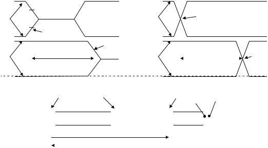
Full-/low-speed signaling uses bit stuffing throughout the packet without exception. If the receiver sees seven consecutive ones anywhere in the packet, then a bit stuffing error has occurred and the packet should be ignored. The time interval just before an EOP is a special case. The last data bit before the EOP can become stretched by hub switching skews. This is known as dribble and can lead to the case illustrated in Figure 7-33, which shows where dribble introduces a sixth bit that does not require a bit stuff. Therefore, the receiver must accept a packet for which there are up to six full bit times at the port with no transitions prior to the EOP.
Data Encoding Sequence:
Raw Data
Sync Pattern |
|
|
|
|
Packet Data |
|
|
||||
|
|
|
|
|
|
Stuffed Bit
Bit Stuffed Data
Sync Pattern |
|
|
|
|
|
|
|
|
Packet Data |
||
|
|
|
|
|
|||||||
|
|
|
|
|
|
|
|
|
|
|
|
|
|
|
|
|
|
|
Six Ones |
|
|
|
|
|
|
|
|
|
|
|
|
|
|||
|
|
|
|
|
|
|
|
|
|
|
|
|
|
|
|
|
|
|
|
|
|
|
|
NRZI |
Idle |
|
|
|
|
|
|
|
|
|
|
|
|
|
|
|
|
|
|
|
|
Encoded Data |
|
|
|
|
|
|
|
|
|
|
|
|
|
|
|
|
|
|
|
|
|
|
|
|
|
|
Sync Pattern |
|
|
|
|
|
Packet Data |
|
|
|
|
||||||
|
|
|
|
|
|
|
|
|
|
|
|
|
|
|
|
||||||
|
|
|
|
|
|
|
|
|
|
|
|
|
|
|
|
|
|
|
|
|
|
Figure 7-32. Bit Stuffing
157
Universal Serial Bus Specification Revision 2.0
Transmitted |
0 |
0 |
1 |
|
|
1 |
|
1 |
1 |
|
|
1 EOP |
|
EOP J |
|
|
|
|
|||||||||||||||||||||||||||||
|
Data |
|
|
|
|
|
|
|
|
|
|
||||||||||||||||||||||||||||||||||||
|
|
|
|
|
|
|
|
|
|
|
|
|
|
|
|
|
|
|
|
|
|
|
|
|
|
|
|
|
|
|
|
|
|
|
|
|
|
|
|
|
|||||||
|
|
|
|
|
|
|
|
|
|
|
|
|
|
|
|
|
|
|
|
|
|
|
|
|
|
|
|
|
|
|
|
|
|
|
|
|
|
|
|
|
|
|
|
|
|
|
|
|
|
|
|
|
|
|
|
|
|
|
|
|
|
|
|
|
|
CRC |
|
|
|
|
|
|
|
|
|
|
|
|
|
|
|
|
|
|
|
|
|
|
|
|
|
|
|||
|
|
|
Data from |
|
|
|
|
|
|
|
|
|
|
|
|
|
|
|
|
|
|
|
|
|
|
|
|
|
|
|
|
|
|
|
|
|
|
|
|
||||||||
|
|
|
|
|
|
|
|
|
|
|
|
|
|
|
|
|
|
|
|
|
|
|
|
|
|
|
|
|
|
|
|
|
|
|
|
|
|
|
|
|
|
|
|||||
|
|
|
|
|
|
|
|
|
|
|
|
|
|
|
|
|
|
|
|
|
|
|
|
|
|
|
|
|
|
|
|
|
|
|
|
|
|
|
|
|
|
|
|||||
|
|
|
|
|
|
|
|
|
|
|
|
|
|
|
|
|
|
|
|
|
|
|
|
|
|
|
|
|
|
|
|
|
|
|
|
|
|
|
|
|
|
|
|||||
|
|
|
|
|
|
|
|
|
|
|
|
|
|
|
|
|
|
|
|
|
|
|
|
|
|
|
|
|
|
EOP |
|
|
|
|
|
|
|
|
|
||||||||
|
|
Transmitter |
|
|
|
|
|
|
|
|
|
|
|
|
|
|
|
|
|
|
|
|
|
|
|
|
|
|
|
|
|
|
|
|
|||||||||||||
|
|
|
|
|
|
|
|
|
|
|
|
|
|
|
|
|
|
|
|
|
|
|
|
|
|
|
|
|
|
|
|
|
|
|
|
|
|
|
|
|
|
|
|
|
|
|
|
|
|
|
|
|
|
|
|
|
|
|
|
|
|
|
|
|
|
|
|
|
|
|
|
|
|
|
|
|
|
|
|
|
|
|
|
|
|
|
|
|
|
|
|
|
|||
Acceptable |
|
|
|
|
|
|
|
|
|
|
|
|
|
|
|
|
|
CRC |
|
|
|
|
|
|
|
|
|
|
|
|
|
|
|
|
|
|
|
|
|
|
|
|
|
|
|||
|
|
Data at |
|
|
|
|
|
|
|
|
|
|
|
|
|
|
|
|
|
|
|
|
Extra |
|
|
|
|
|
|
|
|
|
|
|
|
||||||||||||
|
|
|
|
|
|
|
|
|
|
|
|
|
|
|
|
|
|
|
|
|
|
|
|
|
|
|
|
|
|
|
|
|
|
|
|
|
|
||||||||||
|
|
|
|
|
|
|
|
|
|
|
|
|
|
|
|
|
|
|
|
|
|
|
|
|
|
|
|
|
|
|
|
|
|
|
|
|
|
||||||||||
|
|
|
|
|
|
|
|
|
|
|
|
|
|
|
|
|
|
|
|
|
|
|
|
|
|
|
|
|
|
|
|
|
|
|
|
|
|
||||||||||
Extra Bit, |
|
|
|
|
|
|
|
|
|
|
|
|
|
|
|
|
|
|
|
|
|
|
|
|
|
|
|
|
EOP |
|
|
|
|
|
|||||||||||||
No Error |
|
|
Receiver |
|
|
|
|
|
|
|
|
|
|
|
|
|
|
|
|
|
|
|
|
|
|
|
|
|
bit |
|
|
|
|
|
|
|
|
|
|
|
|
||||||
|
|
|
|
|
|
|
|
|
|
|
|
|
|
|
|
|
|
|
|
|
|
|
|
|
|
|
|
|
|
|
|
|
|
|
|
|
|
|
|
|
|
||||||
|
|
|
|
|
|
|
|
|
|
|
|
|
|
|
|
|
|
|
|
|
|
|
|
|
|
|
|
|
|
|
|
|
|
|
|
|
|
|
|
|
|
|
|
|
|
|
|
Figure 7-33. Illustration of Extra Bit Preceding EOP (Full-/low-speed)
Power Up
No Packet
Transmission
Idle
Begin Packet Transmission
Reset Bit
Counter to 0
Get Next
Bit
=0 |
Bit |
=1 |
|
Value? |
|
|
Increment |
|
|
the Counter |
|
No |
Counter |
Yes |
|
= 6? |
|
|
Insert a |
|
|
Zero Bit |
|
|
Reset Bit |
|
|
Counter to 0 |
|
No |
Is Packet |
Yes |
|
Transfer |
|
|
|
|
|
Done? |
|
Figure 7-34. Flow Diagram for Bit Stuffing
158

Universal Serial Bus Specification Revision 2.0
7.1.9.2 High-Speed
High-speed signaling uses bit stuffing throughout the packet, with the exception of the intentional bit stuff errors used in the high-speed EOP as described in Section 7.1.13.2.
7.1.10 Sync Pattern
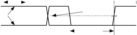
The SYNC pattern used for low-/full-speed transmission is required to be 3 KJ pairs followed by 2 K’s for a total of eight symbols. Figure 7-35 shows the NRZI bit pattern, which is prefixed to each low-/full-speed packet.
15=, 'DWD |
|
|
|
6<1& 3$77(51 |
|
|
|
|
|
||
,GOH |
|
|
3,' 3,' |
||
(QFRGLQJ |
|
|
|
|
|
|
|
Figure 7-35. |
Sync Pattern (Low-/full-speed) |
||
The SYNC pattern used for high-speed transmission is required to be 15 KJ pairs followed by 2 K’s, for a total of 32 symbols. Hubs are allowed to drop up to 4 bits from the start of the SYNC pattern when repeating packets. Hubs must not corrupt any repeated bits of the SYNC field, however. Thus, after being repeated by 5 hubs, a packet’s SYNC field may be as short as 12 bits.
7.1.11 Data Signaling Rate
The high-speed data rate (THSDRAT) is nominally 480.00 Mb/s, with a required bit rate accuracy of ± 500 ppm. For hosts, hubs, and high-speed capable functions, the required data-rate accuracy when transmitting at any speed is ±0.05% (500 ppm). The full-speed rate for such hubs and functions is T FDRATHS. The low-speed rate for such hubs is TLDRATHS (a low-speed function must not support high-speed).
The full-speed data rate is nominally 12.000 Mb/s. For full-speed only functions, the required data-rate when transmitting (TFDRATE) is 12.000 Mb/s ± 0.25% (2,500 ppm).
The low-speed data rate is nominally 1.50 Mb/s. For low-speed functions, the required data-rate when transmitting (TLDRATE) is 1.50 Mb/s ± 1.5% (15,000 ppm). This allows the use of resonators in low cost, lowspeed devices.
Hosts and hubs must be able to receive data from any compliant low-speed, full-speed, or high-speed source. High-speed capable functions must be able to receive data from any compliant full-speed or high-speed source. Full-speed only functions must be able to receive data from any compliant full-speed source. Low-speed only functions must be able to receive data from any compliant low-speed source.
The above accuracy numbers include contributions from all sources:
•Initial frequency accuracy
•Crystal capacitive loading
•Supply voltage on the oscillator
•Temperature
•Aging
7.1.12 Frame Interval
The USB defines a frame interval (TFRAME) to be 1.000 ms ±500 ns long. The USB defines a microframe interval (THSFRAM) to be 125.0 µs ±62.5 ns long. The (micro )frame interval is measured from any point in an SOF token in one (micro)frame to the same point in the SOF token of the next (micro)frame.
159