

usb_2.0_english
.pdfUniversal Serial Bus Specification Revision 2.0
(LSb) |
(MSb) |
||||
Port 0 |
Port 1 |
Port 2 |
Port 3 Port 4 |
Port 5 |
Port 6 |
|
|
|
|
|
|
Figure 8-11. Port Field
The S (Speed) field specifies the speed for this interrupt or control transaction as follows:
•0 – Full speed
•1 – Low speed
For bulk IN/OUT and isochronous IN start-splits, the S field must be set to zero. For bulk/control IN/OUT, interrupt IN/OUT, and isochronous IN start-splits, the E field must be set to zero.
For full-speed isochronous OUT start-splits, the S1 (Start) and E (End) fields specify how the high-speed data payload corresponds to data for a full-speed data packet as shown in Table 8-2.
Table 8-2. Isochronous OUT Payload Continuation Encoding
S |
E |
High-speed to Full-speed Data Relation |
|
|
|
00 High-speed data is the middle of the fullspeed data payload
01 High-speed data is the end of the full-speed data payload
10 High-speed data is the beginning of the fullspeed data payload
11 High-speed data is all of the full-speed data payload.
Isochronous OUT start-split transactions use these encodings to allow the hub to detect various error cases due to lack of receiving start-split transactions for an endpoint with a data payload that requires multiple start-splits. For example, a large full-speed data payload may require three start-split transactions: a startsplit/beginning, a start-split/middle and a start-split/end. If any of these transactions is not received by the hub, it will either ignore the full-speed transaction (if the start-split/beginning is not received), or it will force an error for the corresponding full-speed transaction (if one of the other two transactions are not received). Other error conditions can be detected by not receiving a start-split during a microframe.
The ET (Endpoint Type) field specifies the endpoint type of the full-/low-speed transaction as shown in Table 8-3.
1 The S bit can be reused for these encodings since isochronous transactions must not be low speed.
203
Universal Serial Bus Specification Revision 2.0
Table 8-3. Endpoint Type Values in Split Special Token
ET value |
Endpoint |
(msb:lsb) |
Type |
|
|
00 |
Control |
|
|
01 |
Isochronous |
|
|
10Bulk
11Interrupt
This field tells the hub which split transaction state machine to use for this full-/low-speed transaction.
The full-/low-speed device address and endpoint number information is contained in the normal token packet that follows the SPLIT special token packet.
8.4.2.3 Complete-Split Transaction Token
|
(lsb) |
|
|
|
|
|
|
(msb) |
|
|
|
|
|
|
|
|
|
|
|
Field |
|
SPLIT |
Hub |
SC |
Port |
S |
U |
ET |
CRC5 |
|
|
PID |
Addr |
|
|
|
|
|
|
Bits |
8 |
7 |
1 |
7 |
1 |
1 |
2 |
5 |
|
Figure 8-12. Complete-split (CSPLIT) Transaction Token
A SPLIT special token packet with the SC field set to one indicates that this is a complete-split transaction (CSPLIT).
The U bit is reserved/unused and must be reset to zero(0B).
The other fields of the complete-split token packet have the same definitions as for the start-split token packet.
8.4.3 Start-of-Frame Packets
Start-of-Frame (SOF) packets are issued by the host at a nominal rate of once every 1.00 ms ± 0.0005 ms for a full-speed bus and 125 µs ± 0.0625 µs for a high-speed bus. SOF packets consist of a PID indicating packet type followed by an 11-bit frame number field as illustrated in Figure 8-13.
|
(lsb) |
|
(msb) |
|
|
|
|
|
|
Field |
|
PID |
FrameNumber |
CRC5 |
|
|
|
|
|
Bits |
8 |
11 |
5 |
|
|
|
|
|
|
Figure 8-13. SOF Packet
The SOF token comprises the token-only transaction that distributes an SOF marker and accompanying frame number at precisely timed intervals corresponding to the start of each frame. All high-speed and fullspeed functions, including hubs, receive the SOF packet. The SOF token does not cause any receiving function to generate a return packet; therefore, SOF delivery to any given function cannot be guaranteed.
204

Universal Serial Bus Specification Revision 2.0
The SOF packet delivers two pieces of timing information. A function is informed that an SOF has occurred when it detects the SOF PID. Frame timing sensitive functions, that do not need to keep track of frame number (e.g., a full-speed operating hub), need only decode the SOF PID; they can ignore the frame number and its CRC. If a function needs to track frame number, it must comprehend both the PID and the time stamp. Full-speed devices that have no particular need for bus timing information may ignore the SOF packet.
8.4.3.1 USB Frames and Microframes
USB defines a full-speed 1 ms frame time indicated by a Start Of Frame (SOF) packet each and every 1ms period with defined jitter tolerances. USB also defines a high-speed microframe with a 125 s frame time with related jitter tolerances (See Chapter 7). SOF packets are generated (by the host controller or hub transaction translator) every 1ms for full-speed links. SOF packets are also generated after the next seven 125 s periods for high-speed links.
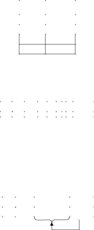
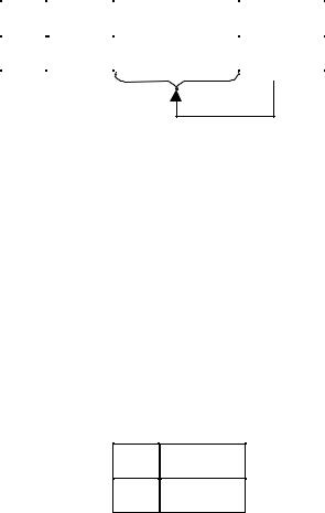
Figure 8-14 shows the relationship between microframes and frames.
Full / Low-Speed Frame Size (1 ms)
1 ms |
|
|
1 ms |
|
|
|
|
|
|||||
|
|
|
|
|
|
||||||||
|
|
|
|
|
|
|
|
|
|
|
|
|
|
|
|
|
|
|
|
|
|
|
|
|
|
|
|
|
|
|
|
|
|
|
|
|
|
|
|
|
|
|
Full-Speed USB Frame Ticks |
|
Full-Speed Isochronous Data Payload |
||||||||||
|
|
||||||||||||
|
|
||||||||||||
|
|
|
|
|
|
|
|
|
|
|
|
|
|
|
|
|
|
|
|
|
|
|
|
|
|
|
|
High-Speed Micro-Frames (125 us)
|
|
|
|
|
|
|
|
|
|
|
|
|
|
|
|
|
|
|
|
|
|
|
|
|
|
|
|
|
|
|
|
|
|
|
|
|
|
|
|
|
|
|
|
|
|
|
|
|
|
|
|
|
|
|
|
|
|
|
|
|
|
|
|
|
|
|
|
|
|
|
|
|
|
|
|
|
|
|
|
|
|
|
|
|
|
|
|
|
|
|
|
|
|
|
|
|
|
|
|
|
|
|
|
|
|
|
|
|
|
|
|
|
|
|
|
|
|
|
|
|
|
|
|
|
|
|
|
|
|
|
|
|
|
|
|
|
|
|
|
|
|
|
|
|
|
|
|
|
|
|
|
|
|
|
|
|
|
|
|
|
|
|
|
|
USB 2.0 Micro-Frame Ticks |
|
High-Speed Isochronous Data Payload |
||||||||||||||||||||||||||||||||||||||||||||||||
|
|
|
|
||||||||||||||||||||||||||||||||||||||||||||||||||
|
|||||||||||||||||||||||||||||||||||||||||||||||||||||
|
|
|
|||||||||||||||||||||||||||||||||||||||||||||||||||
|
|
|
(1/8th Full-Speed Frame) |
|
|||||||||||||||||||||||||||||||||||||||||||||||||
|
|
|
|
|
|
|
|
|
|
|
|
|
|
|
|
|
|
|
|
|
|
|
|
|
|
|
|
|
|||||||||||||||||||||||||
|
|
|
|
|
|
|
|
|
|
|
|
|
|
|
|
|
|
|
|
|
|
|
|
|
|
|
|
|
|
|
|
|
|
|
|
|
|
|
|
|
|
|
|
|
|
|
|
|
|
|
|
|
|
Figure 8-14. Relationship between Frames and Microframes
High-speed devices see an SOF packet with the same frame number eight times (every 125 s) during each 1 ms period. If desired, a high-speed device can locally determine a particular microframe “number” by detecting the SOF that had a different frame number than the previous SOF and treating that as the zeroth microframe. The next seven SOFs with the same frame number can be treated as microframes 1 through 7.
205
Universal Serial Bus Specification Revision 2.0
8.4.4 Data Packets
A data packet consists of a PID, a data field containing zero or more bytes of data, and a CRC as shown in Figure 8-15. There are four types of data packets, identified by differing PIDs: DATA0, DATA1, DATA2 and MDATA. Two data packet PIDs (DATA0 and DATA1) are defined to support data toggle synchronization (refer to Section 8.6). All four data PIDs are used in data PID sequencing for high bandwidth high-speed isochronous endpoints (refer to Section 5.9). Three data PIDs (MDATA, DATA0, DATA1) are used in split transactions (refer to Sections 11.17-11.21).
|
(lsb) |
|
(msb) |
|
|
|
|
|
|
Field |
|
PID |
DATA |
CRC16 |
|
|
|
|
|
Bits |
8 |
0-8192 |
16 |
|
|
|
|
|
|
Figure 8-15. Data Packet Format
Data must always be sent in integral numbers of bytes. The data CRC is computed over only the data field in the packet and does not include the PID, which has its own check field.
The maximum data payload size allowed for low-speed devices is 8 bytes. The maximum data payload size for full-speed devices is 1023. The maximum data payload size for high-speed devices is 1024 bytes.
8.4.5 Handshake Packets
Handshake packets, as shown in Figure 8-16, consist of only a PID. Handshake packets are used to report the status of a data transaction and can return values indicating successful reception of data, command acceptance or rejection, flow control, and halt conditions. Only transaction types that support flow control can return handshakes. Handshakes are always returned in the handshake phase of a transaction and may be returned, instead of data, in the data phase. Handshake packets are delimited by an EOP after one byte of packet field. If a packet decodes as an otherwise valid handshake but does not terminate with an EOP after one byte, it must be considered invalid and ignored by the receiver.
(lsb) (msb)
Field PID
Bits 8
Figure 8-16. Handshake Packet
There are four types of handshake packets and one special handshake packet:
•ACK indicates that the data packet was received without bit stuff or CRC errors over the data field and that the data PID was received correctly. ACK may be issued either when sequence bits match and the receiver can accept data or when sequence bits mismatch and the sender and receiver must resynchronize to each other (refer to Section 8.6 for details). An ACK handshake is applicable only in transactions in which data has been transmitted and where a handshake is expected. ACK can be returned by the host for IN transactions and by a function for OUT, SETUP, or PING transactions.
•NAK indicates that a function was unable to accept data from the host (OUT) or that a function has no data to transmit to the host (IN). NAK can only be returned by functions in the data phase of IN transactions or the handshake phase of OUT or PING transactions. The host can never issue NAK.
206
Universal Serial Bus Specification Revision 2.0
NAK is used for flow control purposes to indicate that a function is temporarily unable to transmit or receive data, but will eventually be able to do so without need of host intervention.
•STALL is returned by a function in response to an IN token or after the data phase of an OUT or in response to a PING transaction (see Figure 8-30 and Figure 8-38). STALL indicates that a function is unable to transmit or receive data, or that a control pipe request is not supported. The state of a function after returning a STALL (for any endpoint except the default endpoint) is undefined. The host is not permitted to return a STALL under any condition.
The STALL handshake is used by a device in one of two distinct occasions. The first case, known as “functional stall,” is when the Halt feature associated with the endpoint is set. (The Halt feature is specified in Chapter 9 of this document.) A special case of the functional stall is the “commanded stall.” Commanded stall occurs when the host explicitly sets the endpoint’s Halt feature, as detailed in Chapter 9. Once a function’s endpoint is halted, the function must continue returning STALL until the condition causing the halt has been cleared through host intervention.
The second case, known as “protocol stall,” is detailed in Section 8.5.3. Protocol stall is unique to control pipes. Protocol stall differs from functional stall in meaning and duration. A protocol STALL is returned during the Data or Status stage of a control transfer, and the STALL condition terminates at the beginning of the next control transfer (Setup). The remainder of this section refers to the general case of a functional stall.
•NYET is a high-speed only handshake that is returned in two circumstances. It is returned by a highspeed endpoint as part of the PING protocol described later in this chapter. NYET may also be returned by a hub in response to a split-transaction when the full-/low-speed transaction has not yet been completed or the hub is otherwise not able to handle the split-transaction. See Chapter 11 for more details.
•ERR is a high-speed only handshake that is returned to allow a high-speed hub to report an error on a full-/low-speed bus. It is only returned by a high-speed hub as part of the split transaction protocol. See Chapter 11 for more details.
8.4.6 Handshake Responses
Transmitting and receiving functions must return handshakes based upon an order of precedence detailed in Table 8-4 through Table 8-6. Not all handshakes are allowed, depending on the transaction type and whether the handshake is being issued by a function or the host. Note that if an error occurs during the transmission of the token to the function, the function will not respond with any packets until the next token is received and successfully decoded.
8.4.6.1 Function Response to IN Transactions
Table 8-4 shows the possible responses a function may make in response to an IN token. If the function is unable to send data, due to a halt or a flow control condition, it issues a STALL or NAK handshake, respectively. If the function is able to issue data, it does so. If the received token is corrupted, the function returns no response.
207
|
Universal Serial Bus Specification Revision 2.0 |
||
|
Table 8-4. Function Responses to IN Transactions |
||
|
|
|
|
Token Received |
Function Tx |
Function Can |
Action Taken |
Corrupted |
Endpoint Halt |
Transmit Data |
|
|
Feature |
|
|
Yes |
Don’t care |
Don’t care |
Return no response |
|
|
|
|
No |
Set |
Don’t care |
Issue STALL handshake |
|
|
|
|
No |
Not set |
No |
Issue NAK handshake |
|
|
|
|
No |
Not set |
Yes |
Issue data packet |
|
|
|
|
8.4.6.2 Host Response to IN Transactions
Table 8-5 shows the host response to an IN transaction. The host is able to return only one type of handshake: ACK. If the host receives a corrupted data packet, it discards the data and issues no response. If the host cannot accept data from a function, (due to problems such as internal buffer overrun) this condition is considered to be an error and the host returns no response. If the host is able to accept data and the data packet is received error-free, the host accepts the data and issues an ACK handshake.
Table 8-5. Host Responses to IN Transactions
Data Packet |
Host Can |
Handshake Returned by Host |
Corrupted |
Accept Data |
|
Yes |
N/A |
Discard data, return no response |
|
|
|
No |
No |
Discard data, return no response |
|
|
|
No |
Yes |
Accept data, issue ACK |
|
|
|
8.4.6.3 Function Response to an OUT Transaction
Handshake responses for an OUT transaction are shown in Table 8-6. Assuming successful token decode, a function, upon receiving a data packet, may return any one of the three handshake types. If the data packet was corrupted, the function returns no handshake. If the data packet was received error-free and the function’s receiving endpoint is halted, the function returns STALL. If the transaction is maintaining sequence bit synchronization and a mismatch is detected (refer to Section 8.6 for details), then the function returns ACK and discards the data. If the function can accept the data and has received the data error-free, it returns ACK. If the function cannot accept the data packet due to flow control reasons, it returns NAK.
208

Universal Serial Bus Specification Revision 2.0
Table 8-6. Function Responses to OUT Transactions in Order of Precedence
Data Packet |
Receiver |
Sequence Bits |
Function Can |
Handshake Returned |
Corrupted |
Halt |
Match |
Accept Data |
by Function |
|
Feature |
|
|
|
Yes |
N/A |
N/A |
N/A |
None |
|
|
|
|
|
No |
Set |
N/A |
N/A |
STALL |
|
|
|
|
|
No |
Not set |
No |
N/A |
ACK |
|
|
|
|
|
No |
Not set |
Yes |
Yes |
ACK |
|
|
|
|
|
No |
Not set |
Yes |
No |
NAK |
|
|
|
|
|
8.4.6.4 Function Response to a SETUP Transaction
SETUP defines a special type of host-to-function data transaction that permits the host to initialize an endpoint’s synchronization bits to those of the host. Upon receiving a SETUP token, a function must accept the data. A function may not respond to a SETUP token with either STALL or NAK, and the receiving function must accept the data packet that follows the SETUP token. If a non-control endpoint receives a SETUP token, it must ignore the transaction and return no response.
8.5 Transaction Packet Sequences
The packets that comprise a transaction varies depending on the endpoint type. There are four endpoint types: bulk, control, interrupt, and isochronous.
A host controller and device each require different state machines to correctly sequence each type of transaction. Figures in the following sections show state machines that define the correct sequencing of packets within a transaction of each type. The diagrams should not be taken as a required implementation, but to specify the required behavior.
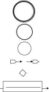
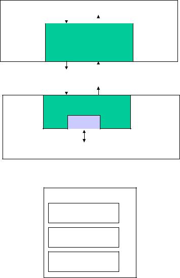
Figure 8-17 shows the legend for the state machine diagrams. A circle with a three-line border indicates a reference to another (hierarchical) state machine. A circle with a two-line border indicates an initial state. A circle with a single-line border represents a simple state.
209
Universal Serial Bus Specification Revision 2.0
State
Hierarchy
Initial
State
State
&
-Contains other state machines
-Initial state of a state machine
-State in a state machine
-Entry and exit of state machine
-Joint used to connect transitions
Condition
Actions
-Transition: taken when condition is true and performs actions
Figure 8-17. Legend for State Machines
The “tab” shapes with arrows are the entry or exit (respectively in the legend) to/from the state machine. The entry/exit relates to another state in a state machine at a higher level in the state machine hierarchy.
A diamond (joint) is used to join several transitions to a common point. A joint allows a single input transition with multiple output transitions or multiple input transitions and a single output transition. All conditions on the transitions of a path involving a joint must be true for the path to be taken. A path is simply a sequence of transitions involving one or more joints.
A transition is labeled with a block with a line in the middle separating the (upper) condition and the (lower) actions. The condition is required to be true to take the transition. The syntax for actions and conditions is VHDL. The actions are performed if the transition is taken. A circle includes a name in bold and optionally one or more actions that are performed upon entry to the state.
The host controller and device state machines are in a context as shown in Figure 8-18. The host controller determines the next transaction to run for an endpoint and issues a command (HC_cmd) to the host controller state machines. This causes the host controller state machines to issue one or more packets to move over the downstream bus (HSD1).
The device receives these packets from the bus (HSD2), reacts to the received packet, and interacts with its function(s) via the state of the corresponding endpoint (in the EP_array). Then the device may respond with a packet on the upstream bus (HSU1). The host controller state machines can receive a packet from the bus (HSU2) and provide a result of the transaction back to the host controller (HC_resp). The details of what packets are sent on the bus is determined by the transfer type for the endpoint and what bus activity the state machines observe.
The state machines are presented in a hierarchical form. Figure 8-19 shows the top level state machines for the host controller. The non-split transactions are presented in the remainder of this chapter. The split transaction state machines (HC_Do_start and HC_Do_complete) are described and shown in Chapter 11.
210
Universal Serial Bus Specification Revision 2.0
|
Transaction |
Transaction |
Host |
||||
|
commands |
Results |
|||||
|
|
|
|
|
|
|
Controller |
|
|
|
|
|
|
|
|
|
|
|
|
|
|
|
|
|
HC_cmd |
|
HC_resp |
|
|||
|
|
|
|
||||
|
|
|
|
|
|
|
|
Host state machines
HSD1 HSU2
|
|
|
|
|
Downstream |
|
|
Upstream |
|
Bus |
|
|
Bus |
|
|
|
|
|
|
HSD2 HSU1
Device state machines
Ep array
Device
Functions
Figure 8-18. State Machine Context Overview
HC_Process_command
HC_Do_start
HC_Do_complete
HC_Do_nonsplit
Figure 8-19. Host Controller Top Level Transaction State Machine Hierarchy Overview
The host controller state machines are located in the host controller. The host controller causes packets to be issued downstream (labeled as HSD1) and it receives upstream packets (labeled as HSU2).
The device state machines are located in the device. The device causes packets to be issued upstream (labeled as HSU1) and it receives downstream packets (labeled as HSD2).
The host controller has commands that tell it what transaction to issue next for an endpoint. The host controller tracks transactions for several endpoints. The host controller state machines sequence to determine what the host controller needs to do next for the current endpoint. The device has a state for each of its endpoints. The device state machines sequence to determine what reaction the device has to a transaction.
The appendix includes some declarations that were used in constructing the state machines and may be useful in understanding additional details of the state machines. There are several pseudo-code procedures and functions for conditions and actions. Simple descriptions of them are also included in the appendix.
Figure 8-20 shows an overview of the overall state machine hierarchy for the host controller for the nonsplit transaction types. Figure 8-21 shows the hierarchy of the device state machines. The state machines
211

Universal Serial Bus Specification Revision 2.0
common to endpoint types are presented first. The lowest level endpoint type specific state machines are presented in each following endpoint type section.
HC_Do_nonsplit
HC_HS_BCO
HC_Do_BCINTO
HC_Do_BCINTI
HC_Do_IsochO
HC_Do_IsochI
Figure 8-20. Host Controller Non-split Transaction State Machine Hierarchy Overview
Device_Process_trans
Dev_do_OUT
Dev_Do_IsochO
Dev_Do_BCINTO
Dev_HS_BCO
Dev_do_IN
Dev_Do_IsochI
Dev_Do_BCINTI
Dev_HS_ping
Figure 8-21. Device Transaction State Machine Hierarchy Overview
212