

usb_2.0_english
.pdfUniversal Serial Bus Specification Revision 2.0
Table 7-10. Low-speed Source Electrical Characteristics (Continued)
Parameter |
Symbol |
Conditions |
Min. |
Max. |
Units |
Source SE0 interval of EOP |
TLEOPT |
Figure 7-50 |
1.25 |
1.50 |
µs |
Receiver SE0 interval of EOP |
TLEOPR |
Note 13; Section 7.1.13.2; |
670 |
|
ns |
|
|
Figure 7-50 |
|
|
|
Width of SE0 interval during |
TLST |
Section 7.1.4 |
|
210 |
ns |
differential transition |
|
|
|
|
|
Table 7-11. Hub/Repeater Electrical Characteristics
Parameter |
Symbol |
Conditions |
Min. |
Max. |
Units |
Full-speed Hub Characteristics (as measured at connectors):
Driver Characteristics: |
|
Upstream facing port and |
|
|
|
(Refer to Table 7-9) |
|
downstream facing ports |
|
|
|
|
|
configured as full-speed |
|
|
|
Hub Differential Data Delay: |
|
Note 7, 8 |
|
|
|
(with cable) |
THDD1 |
Figure 7-52A |
|
70 |
ns |
(without cable) |
THDD2 |
Figure 7-52B |
|
44 |
ns |
Hub Differential Driver Jitter: |
|
Note 7, 8; Figure 7-52, |
|
|
|
(including cable) |
|
Section 7.1.14 |
|
|
|
To Next Transition |
THDJ1 |
|
-3 |
3 |
ns |
For Paired Transitions |
THDJ2 |
|
-1 |
1 |
ns |
Data Bit Width Distortion after SOP |
TFSOP |
Note 8; Figure 7-52 |
-5 |
5 |
ns |
Hub EOP Delay Relative to THDD |
TFEOPD |
Note 8; Figure 7-53 |
0 |
15 |
ns |
Hub EOP Output Width Skew |
TFHESK |
Note 8; Figure 7-53 |
-15 |
15 |
ns |
Low-speed Hub Characteristics (as measured at connectors):
Driver Characteristics: |
|
Downstream facing ports |
|
|
|
(Refer to Table 7-10) |
|
configured as low-speed |
|
|
|
Hub Differential Data Delay |
TLHDD |
Note 7, 8; Figure 7-52 |
|
300 |
ns |
Hub Differential Driver Jitter |
|
Note 7, 8; Figure 7-52 |
|
|
|
(including cable): |
|
|
|
|
|
Downstream facing port : |
|
|
|
|
|
To Next Transition |
TLDHJ1 |
|
-45 |
45 |
ns |
For Paired Transitions |
TLDHJ2 |
|
-15 |
15 |
ns |
Upstream facing port: |
|
|
|
|
|
To Next Transition |
TLUHJ1 |
|
-45 |
45 |
ns |
For Paired Transitions |
TLUHJ2 |
|
-45 |
45 |
ns |
Data Bit Width Distortion after SOP |
TLSOP |
Note 8; Figure 7-52 |
-60 |
60 |
ns |
Hub EOP Delay Relative to THDD |
TLEOPD |
Note 8; Figure 7-53 |
0 |
200 |
ns |
Hub EOP Output Width Skew |
TLHESK |
Note 8; Figure 7-53 |
-300 |
+300 |
ns |
183

Universal Serial Bus Specification Revision 2.0
Table 7-11. Hub/Repeater Electrical Characteristics (Continued)
Parameter |
Symbol |
Conditions |
Min. |
Max. |
Units |
High-speed Hub Characteristics (as measured at connectors):
Driver Characteristics: |
|
Upstream facing port and |
(Refer to Table 7-8) |
|
downstream facing ports |
|
|
configured as high-speed |
Hub Data Delay (without cable): |
THSHDD |
Section 7.1.14.2 |
|
|
|
36 highspeed bit times + 4 ns
Hub Data Jitter: |
|
Specified by eye patterns |
|
|
|
|
in Section 7.1.2.2 |
|
|
Hub Delay Variation Range: |
THSHDV |
Section 7.1.14.2 |
|
5 high- |
|
|
|
|
speed bit |
|
|
|
|
times |
184

Universal Serial Bus Specification Revision 2.0
Table 7-12. Cable Characteristics (Note 14)
Parameter |
|
|
|
Symbol |
|
Conditions |
Min |
Max |
Units |
|
VBUS Voltage drop for |
|
VBUSD |
Section 7.2.2 |
|
125 |
mV |
||||
detachable cables |
|
|
|
|
|
|
|
|||
GND Voltage drop (for all |
|
VGNDD |
Section 7.2.2 |
|
125 |
mV |
||||
cables) |
|
|
|
|
|
|
|
|
|
|
Differential Cable Impedance |
|
ZO |
(90 Ω |
± 15%); |
76.5 |
103.5 |
Ω |
|||
(full-/high-speed) |
|
|
|
|
|
|
|
|
||
Common mode cable |
|
ZCM |
(30 Ω |
± 30%); |
21.0 |
39.0 |
Ω |
|||
impedance (full-/high-speed) |
|
|
|
|
|
|
|
|||
Cable Delay (one way) |
|
|
Section 7.1.16 |
|
|
|
||||
Full-/high-speed |
|
TFSCBL |
|
|
|
26 |
ns |
|||
Low-speed |
|
|
|
|
TLSCBL |
|
|
|
18 |
ns |
Cable Skew |
|
|
|
|
TSKEW |
Section 7.1.3 |
|
100 |
ps |
|
Unmated Contact Capacitance |
|
CUC |
Section 6.7 |
|
2 |
pF |
||||
Cable loss |
|
|
|
|
|
Specified by table and |
|
|
|
|
|
|
|
|
|
|
graph in Section 7.1.17 |
|
|
|
|
Note 1: Measured at A plug. |
|
|
|
|
|
|
||||
Note 2: Measured at A receptacle. |
|
|
|
|
|
|||||
Note 3: Measured at B receptacle. |
|
|
|
|
|
|||||
Note 4: Measured at A or B connector. |
|
|
|
|
|
|||||
Note 5: Measured with RL of 1.425 kΩ |
to 3.6 V. |
|
|
|
|
|||||
Note 6: Measured with RL of 14.25 kΩ |
to GND. |
|
|
|
|
|||||
Note 7: |
Timing difference between the differential data signals. |
|
|
|
||||||
Note 8: |
Measured at crossover point of differential data signals. |
|
|
|
||||||
Note 9: The maximum load specification is the maximum effective capacitive load allowed that meets the target VBUS drop of 330 mV.
Note 10: Excluding the first transition from the Idle state.
Note 11: The two transitions should be a (nominal) bit time apart.
Note 12: For both transitions of differential signaling.
Note 13: Must accept as valid EOP.
Note 14: Single-ended capacitance of D+ or D- is the capacitance of D+/D- to all other conductors and, if present, shield in the cable. That is, to measure the single-ended capacitance of D+, short D-, VBUS, GND, and the shield line together and measure the capacitance of D+ to the other conductors.
Note 15: For high power devices (non-hubs) when enabled for remote wakeup.
185

Universal Serial Bus Specification Revision 2.0
Table 7-13. Hub Event Timings
Event Description |
Symbol |
Conditions |
Min |
Max |
Unit |
|
|
|
|
|
|
Time to detect a downstream |
TDCNN |
Section 11.5 and |
|
|
|
facing port connect event |
|
Section 7.1.7.3 |
|
|
s |
Awake Hub |
|
|
2.5 |
2000 |
|
Suspended Hub |
|
|
2.5 |
12000 |
s |
|
|
|
|
|
|
Time to detect a disconnect event |
TDDIS |
Section 7.1.7.3 |
2 |
2.5 |
s |
at a hub’s downstream facing port |
|
|
|
|
|
|
|
|
|
|
|
Duration of driving resume to a |
TDRSMDN |
Nominal; Section |
20 |
|
ms |
downstream port; only from a |
|
7.1.7.7 and |
|
|
|
controlling hub |
|
Section 11.5 |
|
|
|
|
|
|
|
|
|
Time from detecting downstream |
TURSM |
Section 7.1.7.7 |
|
1.0 |
ms |
resume to rebroadcast |
|
|
|
|
|
|
|
|
|
|
|
Duration of driving reset to a |
TDRST |
Only for a |
10 |
20 |
ms |
downstream facing port |
|
SetPortFeature |
|
|
|
|
|
(PORT_RESET) |
|
|
|
|
|
request; |
|
|
|
|
|
Section 7.1.7.5 and |
|
|
|
|
|
Section 11.5 |
|
|
|
|
|
|
|
|
|
Overall duration of driving reset to |
TDRSTR |
Only for root hubs; |
50 |
|
ms |
downstream facing port, root hub |
|
Section 7.1.7.5 |
|
|
|
|
|
|
|
|
|
Maximum interval between reset |
TRHRSI |
Only for root hubs; |
|
3 |
ms |
segments used to create TDRSTR |
|
each reset pulse must |
|
|
|
|
|
be of length TDRST; |
|
|
|
|
|
Section 7.1.7.5 |
|
|
|
|
|
|
|
|
|
Time to detect a long K from |
TURLK |
Section 11.6 |
2.5 |
100 |
s |
upstream |
|
|
|
|
|
|
|
|
|
|
|
Time to detect a long SE0 from |
TURLSE0 |
Section 11.6 |
2.5 |
10000 |
s |
upstream |
|
|
|
|
|
|
|
|
|
|
|
Duration of repeating SE0 |
TURPSE0 |
Section 11.6 |
|
23 |
FS bit |
upstream (for low-/full-speed |
|
|
|
|
times |
repeater) |
|
|
|
|
|
|
|
|
|
|
|
Duration of sending SE0 upstream |
TUDEOP |
Optional |
|
2 |
FS bit |
after EOF1 (for low-/full-speed |
|
Section 11.6 |
|
|
times |
repeater) |
|
|
|
|
|
|
|
|
|
|
|
Inter-packet Delay (for high- |
THSIPDSD |
Section 7.1.18.2 |
88 |
|
bit |
speed) for packets traveling in |
|
|
|
|
times |
same direction |
|
|
|
|
|
|
|
|
|
|
|
Inter-packet Delay (for high- |
THSIPDOD |
Section 7.1.18.2 |
8 |
|
bit |
speed) for packets traveling in |
|
|
|
|
times |
opposite direction |
|
|
|
|
|
|
|
|
|
|
|
186
Universal Serial Bus Specification Revision 2.0
Table 7-13. Hub Event Timings (Continued)
Event Description |
Symbol |
|
Conditions |
Min |
Max |
Unit |
|
|
|
|
|
|
|
Inter-packet delay for device/root |
THSRSPIPD1 |
|
Section 7.1.18.2 |
|
192 |
bit |
hub response w/detachable cable |
|
|
|
|
|
times |
for high-speed |
|
|
|
|
|
|
|
|
|
|
|
|
|
Reset Handshake Protocol: |
|
|
|
|
|
|
|
|
|
|
|
|
|
Time for which a Chirp J or Chirp |
TFILT |
Section 7.1.7.5 |
2.5 |
|
s |
|
K must be continuously detected |
|
|
|
|
|
|
(filtered) by hub or device during |
|
|
|
|
|
|
Reset handshake |
|
|
|
|
|
|
|
|
|
|
|
|
|
Time after end of device Chirp K |
TWTDCH |
Section 7.1.7.5 |
|
100 |
s |
|
by which hub must start driving |
|
|
|
|
|
|
first Chirp K in the hub’s chirp |
|
|
|
|
|
|
sequence |
|
|
|
|
|
|
|
|
|
|
|
|
|
Time for which each individual |
TDCHBIT |
Section 7.1.7.5 |
40 |
60 |
s |
|
Chirp J or Chirp K in the chirp |
|
|
|
|
|
|
sequence is driven downstream |
|
|
|
|
|
|
by hub during reset |
|
|
|
|
|
|
|
|
|
|
|
|
|
Time before end of reset by which |
TDCHSE0 |
Section 7.1.7.5 |
100 |
500 |
s |
|
a hub must end its downstream |
|
|
|
|
|
|
chirp sequence |
|
|
|
|
|
|
|
|
|
|
|
|
|
187

Universal Serial Bus Specification Revision 2.0
Table 7-14. Device Event Timings
Parameter |
Symbol |
Conditions |
Min |
Max |
Units |
|
|
|
|
|
|
Time from internal power good to |
TSIGATT |
|
|
100 |
ms |
device pulling D+/D- beyond VIHZ |
|
|
|
|
|
(min) (signaling attach) |
|
Figure 7-29 |
|
|
|
|
|
|
|
|
|
Debounce interval provided by |
TATTDB |
|
|
100 |
ms |
USB system software after attach |
|
|
|
|
|
|
|
Figure 7-29 |
|
|
|
|
|
|
|
|
|
Maximum time a device can draw |
T2SUSP |
Section 7.1.7.6 |
|
10 |
ms |
power >suspend power when bus |
|
|
|
|
|
is continuously in idle state |
|
|
|
|
|
|
|
|
|
|
|
Maximum duration of suspend |
TSUSAVGI |
Section 7.2.3 |
|
1 |
s |
averaging interval |
|
|
|
|
|
|
|
|
|
|
|
Period of idle bus before device |
TWTRSM |
Device must be |
5 |
|
ms |
can initiate resume |
|
remote-wakeup |
|
|
|
|
|
enabled |
|
|
|
|
|
Section 7.1.7.5 |
|
|
|
|
|
|
|
|
|
Duration of driving resume |
TDRSMUP |
Section 7.1.7.7 |
1 |
15 |
ms |
upstream |
|
|
|
|
|
|
|
|
|
|
|
Resume Recovery Time |
TRSMRCY |
Provided by USB |
10 |
|
ms |
|
|
System Software; |
|
|
|
|
|
Section 7.1.7.7 |
|
|
|
|
|
|
|
|
|
Time to detect a reset from |
TDETRST |
Section 7.1.7.5 |
2.5 |
10000 |
s |
upstream for non high-speed |
|
|
|
|
|
capable devices |
|
|
|
|
|
|
|
|
|
|
|
Reset Recovery Time |
TRSTRCY |
Section 7.1.7.5 |
|
10 |
ms |
|
|
|
|
|
|
Inter-packet Delay (for low-/full- |
TIPD |
Section 7.1.18 |
2 |
|
bit |
speed) |
|
|
|
|
times |
|
|
|
|
|
|
Inter-packet delay for device |
TRSPIPD1 |
Section 7.1.18 |
|
6.5 |
bit |
response w/detachable cable for |
|
|
|
|
times |
low-/full-speed |
|
|
|
|
|
|
|
|
|
|
|
Inter-packet delay for device |
TRSPIPD2 |
Section 7.1.18 |
|
7.5 |
bit |
response w/captive cable for low- |
|
|
|
|
times |
/full-speed |
|
|
|
|
|
|
|
|
|
|
|
188
Universal Serial Bus Specification Revision 2.0
Table 7-14. Device Event Timings (Continued)
Parameter |
Symbol |
Conditions |
Min |
Max |
Units |
|
|
|
|
|
|
SetAddress() Completion Time |
TDSETADDR |
Section 9.2.6.3 |
|
50 |
ms |
|
|
|
|
|
|
Time to complete standard |
TDRQCMPLTND |
Section 9.2.6.4 |
|
50 |
ms |
request with no data |
|
|
|
|
|
|
|
|
|
|
|
Time to deliver first and |
TDRETDATA1 |
Section 9.2.6.4 |
|
500 |
ms |
subsequent (except last) data for |
|
|
|
|
|
standard request |
|
|
|
|
|
|
|
|
|
|
|
Time to deliver last data for |
TDRETDATAN |
Section 9.2.6.4 |
standard request |
|
|
|
|
|
Inter-packet delay for device |
THSRSPIPD2 |
Section 7.1.18.2 |
response w/captive cable (high- |
|
|
speed) |
|
|
|
|
|
SetAddress() Completion Time
Time to complete standard request with no data
Reset Handshake Protocol:
Time for which a suspended highspeed capable device must see a continuous SE0 before beginning the high-speed detection handshake
TDSETADDR
TDRQCMPLTND
TFILTSE0
Section 9.2.6.3
Section 9.2.6.4
Section 7.1.7.5
Time a high-speed capable device |
TWTRSTFS |
Section 7.1.7.5 |
|
||
operating in non-suspended full- |
|
|
speed must wait after start of SE0 |
|
|
before beginning the high-speed |
|
|
detection handshake |
|
|
|
|
|
Time a high-speed capable device |
TWTREV |
Section 7.1.7.5 |
|
||
operating in high-speed must wait |
|
|
after start of SE0 before reverting |
|
|
to full-speed |
|
|
|
|
|
Time a device must wait after |
TWTRSTHS |
Section 7.1.7.5 |
|
||
reverting to full-speed before |
|
|
sampling the bus state for SE0 |
|
|
and beginning the high-speed |
|
|
detection handshake |
|
|
|
|
|
50 |
ms |
|
|
192 bit times |
|
+ 52 ns |
|
|
|
50 |
ms |
|
|
50 |
ms |
|
|
|
|
2.5 |
|
s |
|
|
|
2.5 |
3000 |
s |
|
|
|
3.0 |
3.125 |
ms |
|
|
|
100 |
875 |
s |
|
|
|
189
Universal Serial Bus Specification Revision 2.0
Table 7-14. Device Event Timings (Continued)
Parameter |
Symbol |
Conditions |
Min |
Max |
Units |
|
|
|
|
|
|
Minimum duration of a Chirp K |
TUCH |
Section 7.1.7.5 |
1.0 |
|
ms |
|
|
||||
from a high-speed capable device |
|
|
|
|
|
within the reset protocol |
|
|
|
|
|
|
|
|
|
|
|
Time after start of SE0 by which a |
TUCHEND |
Section 7.1.7.5 |
|
7.0 |
ms |
|
|
||||
high-speed capable device is |
|
|
|
|
|
required to have completed its |
|
|
|
|
|
Chirp K within the reset protocol |
|
|
|
|
|
|
|
|
|
|
|
Time between detection of |
TWTHS |
Section 7.1.7.5 |
|
500 |
s |
downstream chirp and entering |
|
|
|
|
|
high-speed state |
|
|
|
|
|
|
|
|
|
|
|
Time after end of upstream chirp |
TWTFS |
Section 7.1.7.5 |
1.0 |
2.5 |
ms |
at which device reverts to full- |
|
|
|
|
|
speed default state if no |
|
|
|
|
|
downstream chirp is detected |
|
|
|
|
|
|
|
|
|
|
|
190
Universal Serial Bus Specification Revision 2.0
7.3.3 Timing Waveforms
TPERIOD 

Differential 
Data Lines 
Crossover
Points
Consecutive
Transitions
N * TPERIOD + TxDJ1
Paired
Transitions
N * TPERIOD + TxDJ2
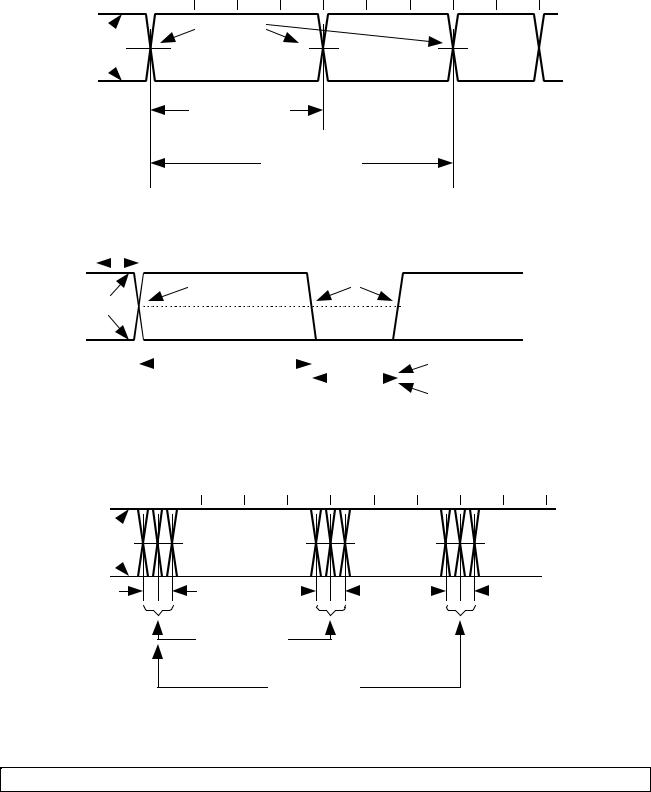
Figure 7-49. Differential Data Jitter for Low-/full-speed
TPERIOD |
|
|
|
|
|
|
|
|
|
|
|
|
|
|
Crossover Point |
|
|
|
|
|
|
|
|
|
|
|||
|
|
|
|
|
|
|
|
|
|
|
|
|
|
|
|
|
||||||||||||
|
|
|
|
|
|
|
|
|
|
Crossover |
|
Extended |
||||||||||||||||
Differential |
|
|
|
|
|
|
|
Point |
|
|
|
|
|
|
|
|
|
|
|
|
|
|
||||||
Data Lines |
|
|
|
|
|
|
|
|
|
|
|
|
|
|
|
|
|
|
|
|
|
|
|
|
|
|
||
|
|
|
|
|
|
|
|
|
|
|
|
|
|
|
|
|
|
|
|
|
|
|
|
|
|
|||
|
|
|
|
|
|
|
|
|
|
|
|
|
|
|
|
|
|
|
|
|
|
|
|
|
||||
|
|
|
|
|
|
|
|
|
|
Diff. Data-to- |
|
|
|
|
|
|
|
|
|
|
|
|
|
|
|
|||
|
|
|
|
|
|
|
|
|
|
SE0 Skew |
|
|
|
|
|
|
|
|
|
Source EOP Width: TFEOPT |
||||||||
|
|
|
|
|
|
|
|
|
|
|
|
|
|
|
|
|
||||||||||||
|
|
|
|
|
|
|
|
|
|
N * TPERIOD + TxDEOP |
|
|
|
|
|
|
|
|
|
|
|
|
|
|
TLEOPT |
|||
|
|
|
|
|
|
|
|
|
|
|
|
|
|
|
|
|
|
|
|
|
|
|
||||||
|
|
|
|
|
|
|
|
|
|
|
|
|
|
|
|
|
|
|
|
|
|
Receiver EOP Width: TFEOPR, |
||||||
|
|
|
|
|
|
|
|
|
|
|
|
|
|
|
|
|
|
|
|
|
||||||||
|
|
|
|
|
|
|
|
|
|
|
|
|
|
|
|
|
|
|
|
|
|
|
|
|
|
|
|
TLEOPR |
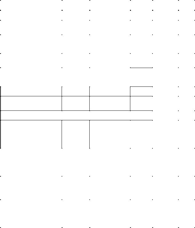
Figure 7-50. Differential-to-EOP Transition Skew and EOP Width for Low-/full-speed
TPERIOD 

Differential 
Data Lines 
TxJR |
|
|
|
|
TxJR1 |
|
|
|
|
TxJR2 |
|
|
|
|
|
|
Consecutive
Transitions
N * TPERIOD + TxJR1
Paired
Transitions
N * TPERIOD + TxJR2
Figure 7-51. Receiver Jitter Tolerance for Low-/full-speed
TPERIOD is the data rate of the receiver that can have the range as defined in Section 7.1.11.
191
Universal Serial Bus Specification Revision 2.0
Upstream |
|
|
|
|
|
|
|
|
|
|
|
|
|
|
Upstream |
|
|
|
|
|
Crossover |
|
|
||||||||
|
|
|
|
|
|
|
|
|
|
|
|
|
|
|
|
|
|
|
|
|
|||||||||||
|
|
|
|
|
|
|
|
|
|
|
|
|
|
|
|
|
|
|
|
|
|||||||||||
|
|
|
|
|
|
|
|
|
|
|
|
|
|
|
|
|
|
|
|
|
|||||||||||
End of |
|
|
|
|
|
|
|
|
|
|
|
|
|
|
|
|
|
|
|
|
|
||||||||||
|
|
|
|
|
|
|
|
|
|
|
|
|
|
Port of hub |
|
|
|
|
|
Point |
|
|
|||||||||
Cable |
|
|
|
|
|
50% Point of |
|
|
|
|
|
|
|
|
|||||||||||||||||
|
|
|
|
|
|
|
|
|
|
|
|
|
|
|
|
|
|
|
|
|
|
||||||||||
|
|
|
|
|
|
|
|
|
|
|
|
|
|
|
|
|
|
|
|
|
|
|
|
||||||||
|
|
|
|
|
|
|
Initial Swing |
|
|
|
|
|
|
|
|
|
|
|
|
|
|
|
|
|
|||||||
VSS |
|
|
|
|
|
|
|
|
|
VSS |
|
|
|
|
|
|
|
|
|
|
50% Point of |
||||||||||
|
|
|
|
|
|
|
|
|
|
|
|
|
|
|
|
|
|
|
|
|
|
|
|
|
|
||||||
|
|
|
|
|
|
|
|
|
|
|
|
|
|
|
|
|
|
|
|
|
|
|
|||||||||
Downstream |
|
|
|
|
|
|
|
|
|
|
|
|
|
|
|
|
|
|
|
|
|
|
|
|
|
|
|
|
|||
|
|
|
|
|
|
|
|
|
|
|
|
|
|
|
|
|
|
|
|
|
|
|
|
|
|
|
|
||||
|
|
|
|
|
Hub Delay |
|
|
|
|
|
|
|
|
Downstream |
|
|
|
|
|
Hub Delay |
|
|
|||||||||
|
|
|
|
|
|
|
|
|
|
|
|
|
|
|
|
|
|
|
|
Initial Swing |
|||||||||||
Port of hub |
|
|
|
|
|
|
|
|
|
|
|
|
|
|
|
|
|
|
|||||||||||||
|
|
|
|
|
Downstream |
|
|
|
|
|
|
|
|
Port of hub |
|
|
|
|
|
Downstream |
|
|
|
|
|||||||
|
|
|
|
|
|
|
|
|
|
|
|
|
|
|
|
|
|
|
|
|
|
|
|
||||||||
|
|
|
|
|
|
|
THDD1 |
|
|
|
|
|
|
|
|
|
|
|
|
|
|
|
|
|
|
|
THDD2 |
|
|
|
|
|
|
|
|
|
|
|
|
|
|
|
|
|
|
|
|
|
|
|
|
|
|
|
|
|
|
|
|
|
|
|
|
VSS |
|
|
|
|
|
|
|
|
|
|
|
|
|
|
|
|
|
VSS |
|
|
|
|
|
|
|
|
|
|
|
||
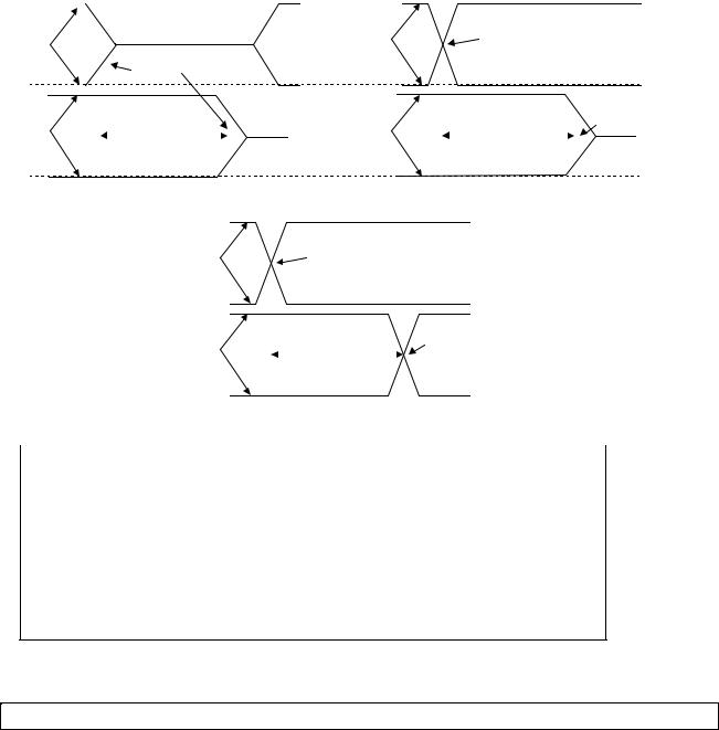
|
A. Downstream Hub Delay with Cable |
|
|
B. Downstream Hub Delay without Cable |
|||||||||||||||||||||||||||
|
|
|
|||||||||||||||||||||||||||||
|
|
|
|
|
|
|
|
|
|
Crossover |
|
|
|
|
|
|
|
|
|
|
|||||||||||
|
|
|
|
|
|
|
Downstream |
|
|
|
|
|
|
|
|
|
|
|
|
||||||||||||
|
|
|
|
|
|
|
Port of hub |
|
|
|
|
Point |
|
|
|
|
|
|
|
|
|
|
|||||||||
|
|
|
|
|
|
|
|
|
|
|
|
|
|
|
|
|
|
|
|
|
|
||||||||||
|
|
|
|
|
|
|
VSS |
|
|
|
|
|
|
|
|
|
|
|
|
|
|
|
|
|
|
|
|||||
|
|
|
|
|
|
|
|
|
|
|
|
|
|
|
|
|
|
|
|
|
|
|
|
|
|
|
|
||||
|
|
|
|
|
|
|
Upstream |
|
|
|
Hub Delay |
|
|
|
|
Crossover |
|
|
|||||||||||||
|
|
|
|
|
|
|
|
|
|
|
|
|
|||||||||||||||||||
|
|
|
|
|
|
|
|
|
|
Upstream |
|
|
|
|
|
Point |
|
|
|||||||||||||
|
|
|
|
|
|
|
Port or End |
|
|
|
|
|
|
|
|
|
|||||||||||||||
|
|
|
|
|
|
|
|
|
|
|
THDD1 |
|
|
|
|
|
|
|
|
|
|
|
|
|
|
|
|||||
|
|
|
|
|
|
|
of Cable |
|
|
|
|
|
|
|
|
|
|
|
|
|
|
|
|
|
|
|
|||||
|
|
|
|
|
|
|
|
|
|
|
|
|
|
|
|
THDD2 |
|
|
|
|
|
|
|
|
|
|
|
|
|
|
|
|
|
|
|
|
|
|
|
|
|
|
|
|
|
|
|
|
|
|
|
|
|
|
|
|
|
|
|
|
|||
|
|
|
|
|
|
|
VSS |
|
|
|
|
|
|
|
|
|
|
|
|
|
|
|
|
|
|||||||
|
|
|
|
|
|
|
C. Upstream Hub Delay with or without Cable |
|
|
||||||||||||||||||||||
|
|
|
|
|
|
|
|
|
|
|
|
|
|
|
|
|
|
|
|
|
|
|
|
|
|
|
|
||||
|
Hub Differential Jitter: |
|
|
|
|
|
|
|
|
|
|
|
|
|
|
|
|
|
|||||||||||||
|
THDJ1 = THDDx(J) - THDDx(K) or THDDx(K) - THDDx(J) |
Consecutive Transitions |
|
|
|||||||||||||||||||||||||||
|
THDJ2 = THDDx(J) - THDDx(J) or THDDx(K) - THDDx(K) |
Paired Transitions |
|
|
|||||||||||||||||||||||||||
Bit after SOP Width Distortion (same as data jitter for SOP and next J transition): TFSOP = THDDx(next J) - THDDx(SOP)
Low-speed timings are determined in the same way for:
TLHDD, TLDHJ1, TLDJH2, TLUHJ1, TLUJH2, and TLSOP
Figure 7-52. Hub Differential Delay, Differential Jitter, and SOP Distortion for Low-/full-speed
Measurement locations referenced in Figure 7-52 and Figure 7-53 are specified in Figure 7-38.
192