

usb_2.0_english
.pdfUniversal Serial Bus Specification Revision 2.0
Pipe |
Pipe |
IRP 1 |
|
|
|
|
IRP 2 |
|
|
|
||
|
Transaction |
|
Transaction |
Transaction |
|
|
Transaction |
|
Transaction |
Transaction |
|
1-0 |
|
1-1 |
1-2 |
|
|
2-0 |
|
2-1 |
2-2 |
|
|
|
|
|
|
|
|
|
|
|
|
|
|
|
|
|
|
|
|
|
|
Frame 1 |
|
|
|
Frame 2 |
|
|
|
|||
|
|
|
|
|
|
|
|
|
|
|
Token Data, |
Token, Data, |
|
Token, Data, |
Token, Data, |
||||||
|
Handshake |
|
Handshake |
|
|
|
Handshake |
|
Handshake |
|
|
(1-0) |
|
(2-0) |
|
|
|
(2-1) |
|
(1-1) |
|
|
|
|
|
|
|
|
|
|
|
|
Figure 5-15. Arrangement of IRPs to Transactions/(Micro)frames
5.11.3 Calculating Bus Transaction Times
When the USB System Software allows a new pipe to be created for the bus, it must calculate how much bus time is required for a given transaction. That bus time is based on the maximum packet size information reported for an endpoint, the protocol overhead for the specific transaction type request, the overhead due to signaling imposed bit stuffing, inter-packet timings required by the protocol, inter-transaction timings, etc. These calculations are required to ensure that the time available in a (micro)frame is not exceeded. The equations used to determine transaction bus time are:
KEY:
Data_bc |
The byte count of data payload |
Host_Delay |
The time required for the host or transaction |
|
translator to prepare for or recover from the |
|
transmission; Host Controller implementation-specific |
Floor() |
The integer portion of argument |
Hub_LS_Setup |
The time provided by the Host Controller for hubs to |
|
enable low-speed ports; measured as the delay from the |
|
end of the PRE PID to the start of the low-speed SYNC; |
|
minimum of four full-speed bit times |
BitStuffTime |
Function that calculates theoretical additional time |
|
required due to bit stuffing in signaling; worst case |
|
is (1.1667*8*Data_bc) |
63
Universal Serial Bus Specification Revision 2.0
High-speed (Input)
Non-Isochronous Transfer (Handshake Included)
= (55 * 8 * 2.083) + (2.083 * Floor(3.167 + BitStuffTime(Data_bc))) + Host_Delay
Isochronous Transfer (No Handshake)
= (38 * 8 * 2.083) + (2.083 * Floor(3.167 + BitStuffTime(Data_bc))) + Host_Delay
High-speed (Output)
Non-Isochronous Transfer (Handshake Included)
= (55 * 8 * 2.083) + (2.083 * Floor(3.167 + BitStuffTime(Data_bc))) + Host_Delay
Isochronous Transfer (No Handshake)
= (38 * 8 * 2.083) + (2.083 * Floor(3.167 + BitStuffTime(Data_bc))) + Host_Delay
Full-speed (Input)
Non-Isochronous Transfer (Handshake Included)
= 9107 + (83.54 * Floor(3.167 + BitStuffTime(Data_bc))) + Host_Delay
Isochronous Transfer (No Handshake)
= 7268 + (83.54 * Floor(3.167 + BitStuffTime(Data_bc))) + Host_Delay
Full-speed (Output)
Non-Isochronous Transfer (Handshake Included)
= 9107 + (83.54 * Floor(3.167 + BitStuffTime(Data_bc))) + Host_Delay
Isochronous Transfer (No Handshake)
= 6265 + (83.54 * Floor(3.167 + BitStuffTime(Data_bc))) + Host_Delay
Low-speed (Input)
= 64060 + (2 * Hub_LS_Setup) +
(676.67 * Floor(3.167 + BitStuffTime(Data_bc))) + Host_Delay
Low-speed (Output)
= 64107 + (2 * Hub_LS_Setup) +
(667.0 * Floor(3.167 + BitStuffTime(Data_bc))) + Host_Delay
The bus times in the above equations are in nanoseconds and take into account propagation delays due to the distance the device is from the host. These are typical equations that can be used to calculate bus time; however, different implementations may choose to use coarser approximations of these times.
The actual bus time taken for a given transaction will almost always be less than that calculated because bit stuffing overhead is data-dependent. Worst case bit stuffing is calculated as 1.1667 (7/6) times the raw time (i.e., the BitStuffTime function multiplies the Data_bc by 8*1.1667 in the equations). This means that there will almost always be time unused on the bus (subject to data pattern specifics) after all regularly scheduled transactions have completed. The bus time made available due to less bit stuffing can be reused as discussed in Section 5.11.5.
The Host_Delay term in the equations is Host Controller-, Transaction Translator(TT)-, and systemdependent and allows for additional time a Host Controller (or TT) may require due to delays in gaining access to memory or other implementation dependencies. This term is incorporated into an implementation of these equations by using the transfer management functions provided by the HCD interface. These equations are typically implemented by a combination of USBD and HCD software working in cooperation.
64
Universal Serial Bus Specification Revision 2.0
The results of these calculations are used to determine whether a transfer or pipe creation can be supported in a given USB configuration.
5.11.4 Calculating Buffer Sizes in Functions and Software
Client software and functions both need to provide buffer space for pending data transactions awaiting their turn on the bus. For non-isochronous pipes, this buffer space needs to be just large enough to hold the next data packet. If more than one transaction request is pending for a given endpoint, the buffering for each transaction must be supplied. Methods to calculate the precise absolute minimum buffering a function may require because of specific interactions defined between its client software and the function are outside the scope of this specification.
The Host Controller is expected to be able to support an unlimited number of transactions pending for the bus subject to available system memory for buffer and descriptor space, etc. Host Controllers are allowed to limit how many (micro)frames into the future they allow a transaction to be requested.
For isochronous pipes, Section 5.12.4 describes details affecting host side and device side buffering requirements. In general, buffers need to be provided to hold approximately twice the amount of data that can be transferred in 1ms for full-speed endpoints or 125 s for high-speed endpoints.
5.11.5 Bus Bandwidth Reclamation
The USB bandwidth and bus access are granted based on a calculation of worst-case bus transmission time and required latencies. However, due to the constraints placed on different transfer types and the fact that the bit stuffing bus time contribution is calculated as a constant but is data-dependent, there will frequently be bus time remaining in each (micro)frame time versus what the (micro)frame transmission time was calculated to be. In order to support the most efficient use of the bus bandwidth, control and bulk transfers are candidates to be moved over the bus as bus time becomes available. Exactly how a Host Controller supports this is implementation-dependent. A Host Controller can take into account the transfer types of pending IRPs and implementation-specific knowledge of remaining (micro)frame time to reuse reclaimed bandwidth.
5.12 Special Considerations for Isochronous Transfers
Support for isochronous data movement between the host and a device is one of the system capabilities supported by the USB. Delivering isochronous data reliably over the USB requires careful attention to detail. The responsibility for reliable delivery is shared by several USB entities:
•The device/function
•The bus
•The Host Controller
•One or more software agents
Because time is a key part of an isochronous transfer, it is important for USB designers to understand how time is dealt with within the USB by these different entities.
Note: The examples in this section describe USB for an example involving full-speed endpoints. The general example details are also appropriate for high-speed endpoints when corresponding changes are made; for example, frame replaced with microframe, 1 ms replaced with 125 s, rate adjustments made between full-speed and high-speed, etc.
All isochronous devices must report their capabilities in the form of device-specific descriptors. The capabilities should also be provided in a form that the potential customer can use to decide whether the device offers a solution to his problem(s). The specific capabilities of a device can justify price differences.
65
Universal Serial Bus Specification Revision 2.0
In any communication system, the transmitter and receiver must be synchronized enough to deliver data robustly. In an asynchronous communication system, data can be delivered robustly by allowing the transmitter to detect that the receiver has not received a data item correctly and simply retrying transmission of the data.
In an isochronous communication system, the transmitter and receiver must remain timeand datasynchronized to deliver data robustly. The USB does not support transmission retry of isochronous data so that minimal bandwidth can be allocated to isochronous transfers and time synchronization is not lost due to a retry delay. However, it is critical that a USB isochronous transmitter/receiver pair still remain synchronized both in normal data transmission cases and in cases where errors occur on the bus.
In many systems that deal with isochronous data, a single global clock is used to which all entities in the system synchronize. An example of such a system is the PSTN (Public Switched Telephone Network). Given that a broad variety of devices with different natural frequencies may be attached to the USB, no single clock can provide all the features required to satisfy the synchronization requirements of all devices and software while still supporting the cost targets of mass-market PC products. The USB defines a clock model that allows a broad range of devices to coexist on the bus and have reasonable cost implementations.
This section presents options or features that can be used by isochronous endpoints to minimize behavior differences between a non-USB implemented function and a USB version of the function. An example is included to illustrate the similarities and differences between the non-USB and USB versions of a function.
The remainder of the section presents the following key concepts:
•USB Clock Model: What clocks are present in a USB system that have impact on isochronous data transfers
•USB (micro)frame Clock-to-function Clock Synchronization Options: How the USB (micro)frame clock can relate to a function clock
•SOF Tracking: Responsibilities and opportunities of isochronous endpoints with respect to the SOF token and USB (micro)frames
•Data Prebuffering: Requirements for accumulating data before generation, transmission, and consumption
•Error Handling: Isochronous-specific details for error handling
•Buffering for Rate Matching: Equations that can be used to calculate buffer space required for isochronous endpoints
5.12.1 Example Non-USB Isochronous Application
The example used is a reasonably generalized example. Other simpler or more complex cases are possible and the relevant USB features identified can be used or not as appropriate.
The example consists of an 8 kHz mono microphone connected through a mixer driver that sends the input data stream to 44 kHz stereo speakers. The mixer expects the data to be received and transmitted at some sample rate and encoding. A rate matcher driver on input and output converts the sample rate and encoding from the natural rate and encoding of the device to the rate and encoding expected by the mixer.
Figure 5-16 illustrates this example.
66
Universal Serial Bus Specification Revision 2.0
Each DD has independent service rate
Mixer Device
Driver
|
|
1 speaker DD |
Rate |
Rate |
service period |
Matcher |
Matcher |
(n sample) |
|
Master Clock |
slop buffer |
|
|
20ms service |
Microphone |
Transfer |
Transfer |
Speaker |
20ms service |
|
period |
Device Driver |
Device Driver |
period |
|||
Complete |
||||||
|
|
Complete |
|
|
||
|
|
Interrupt |
|
|
||
|
|
Interrupt |
|
|
||
|
|
|
|
|
||
|
2x160 Byte Buffer |
DMA |
|
2x3528 Byte Buffer |
Software |
|
|
|
Hardware |
||||
|
(2 Services, |
controller |
|
(2 Services, |
||
|
|
|
||||
|
160 samples per service) |
|
|
882 samples per service) |
|
Traditional Bus
(e.g. PCI, ISA, ...)
Single sample
transfers
1 sample at a time |
|
|
|
1 sample at a time |
|
8MHz Bus Clock |
|
||
|
|
|
|
|
|
|
|
|
|
|
|
|
|
|
Mono |
CD Stereo |
Microphone |
Speakers |
2x1 Byte Buffer |
2x4 Byte Buffer |
(2 Samples) |
(2 Samples) |
8kHz Sample Clock (1 byte/sample)
44.1KHz Sample Clock
(4 bytes/sample)
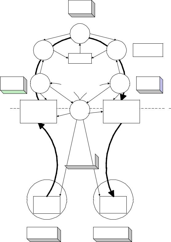
Figure 5-16. Non-USB Isochronous Example
67
Universal Serial Bus Specification Revision 2.0
A master clock (which can be provided by software driven from the real time clock) in the PC is used to awaken the mixer to ask the input source for input data and to provide output data to the output sink. In this example, assume it awakens every 20 ms. The microphone and speakers each have their own sample clocks that are unsynchronized with respect to each other or the master mixer clock. The microphone produces data at its natural rate (one-byte samples, 8,000 times a second) and the speakers consume data at their natural rate (four-byte samples, 44,100 times a second). The three clocks in the system can drift and jitter with respect to each other. Each rate matcher may also be running at a different natural rate than either the mixer driver, the input source/driver, or output sink/driver.
The rate matchers also monitor the long-term data rate of their device compared to the master mixer clock and interpolate an additional sample or merge two samples to adjust the data rate of their device to the data rate of the mixer. This adjustment may be required every couple of seconds, but typically occurs infrequently. The rate matchers provide some additional buffering to carry through a rate match.
Note: Some other application might not be able to tolerate sample adjustment and would need some other means of accommodating master clock-to-device clock drift or else would require some means of synchronizing the clocks to ensure that no drift could occur.
The mixer always expects to receive exactly a service period of data (20 ms service period) from its input device and produce exactly a service period of data for its output device. The mixer can be delayed up to less than a service period if data or space is not available from its input/output device. The mixer assumes that such delays do not accumulate.
The input and output devices and their drivers expect to be able to put/get data in response to a hardware interrupt from the DMA controller when their transducer has processed one service period of data. They expect to get/put exactly one service period of data. The input device produces 160 bytes (ten samples) every service period of 20 ms. The output device consumes 3,528 bytes (882 samples) every 20 ms service period. The DMA controller can move a single sample between the device and the host buffer at a rate much faster than the sample rate of either device.
The input and output device drivers provide two service periods of system buffering. One buffer is always being processed by the DMA controller. The other buffer is guaranteed to be ready before the current buffer is exhausted. When the current buffer is emptied, the hardware interrupt awakens the device driver and it calls the rate matcher to give it the buffer. The device driver requests a new IRP with the buffer before the current buffer is exhausted.
The devices can provide two samples of data buffering to ensure that they always have a sample to process for the next sample period while the system is reacting to the previous/next sample.
The service periods of the drivers are chosen to survive interrupt latency variabilities that may be present in the operating system environment. Different operating system environments will require different service periods for reliable operation. The service periods are also selected to place a minimum interrupt load on the system, because there may be other software in the system that requires processing time.
68
Universal Serial Bus Specification Revision 2.0
5.12.2 USB Clock Model
Time is present in the USB system via clocks. In fact, there are multiple clocks in a USB system that must be understood:
•Sample Clock: This clock determines the natural data rate of samples moving between client software on the host and the function. This clock does not need to be different between non-USB and USB implementations.
•Bus Clock: This clock runs at a 1.000 ms period (1 kHz frequency) on full-speed segments and 125.000 s (8 kHz frequency) on high-speed segments of the bus and is indicated by the rate of SOF
packets on the bus. This clock is somewhat equivalent to the 8 MHz clock in the non-USB example. In the USB case, the bus clock is often a lower-frequency clock than the sample clock, whereas the bus clock is almost always a higher-frequency clock than the sample clock in a non-USB case.
•Service Clock: This clock is determined by the rate at which client software runs to service IRPs that may have accumulated between executions. This clock also can be the same in the USB and non-USB cases.
In most existing operating systems, it is not possible to support a broad range of isochronous communication flows if each device driver must be interrupted for each sample for fast sample rates. Therefore, multiple samples, if not multiple packets, will be processed by client software and then given to the Host Controller to sequence over the bus according to the prenegotiated bus access requirements. Figure 5-17 presents an example for a reasonable USB clock environment equivalent to the non-USB example in Figure 5-16.
69
Universal Serial Bus Specification Revision 2.0
Each DD has independent service rate
Mixer Device
Driver
|
|
|
|
|
|
1 speaker DD |
|
Rate |
|
|
|
Rate |
service period |
|
Matcher |
|
|
|
Matcher |
(n sample) |
|
|
|
Master Clock |
|
|
slop buffer |
|
|
|
|
|
|
|
20ms service |
|
|
|
|
|
|
period |
|
|
|
|
|
|
|
|
Transfer |
|
Transfer |
|
|
|
|
Complete |
|
|
|
|
|
|
|
Complete |
|
|
|
|
|
Interrupt |
|
|
|
|
|
Microphone |
|
Interrupt |
Speaker |
20ms service |
|
1 sample |
|
|
||||
Device Driver |
|
|
|
Device Driver |
period |
|
slop buffer |
|
USB SW |
|
|||
QueueBuffer |
QueueBuffer |
|
||||
|
|
|||||
2x161 Byte Buffer |
Host |
2x3532 Byte Buffer |
|
1x3 Byte Buffer |
|
Software |
(2 Services, |
|
(2 Services, |
|
|
||
|
|
(1 Services, |
|
Hardware |
||
159-161 samples per |
Controller |
881-883 samples per |
|
|
||
|
1 feedback per service |
|
|
|||
service, |
|
service |
|
|
|
|
|
|
1 packets/service) |
|
|
||
20 packets/service) |
|
20 packets/service) |
|
|
|
|
|
|
|
|
|
||
|
|
|
|
|
|
|
1KHz Bus Clock
7-9 Byte Packets
172-184 Byte Packets
7-9 samples per packet
43-46 samples per packet
3 byte packets Feedback Info
Hub
Mono |
|
CD Stereo |
|
Microphone |
|
Speakers |
|
8+9 Byte Buffer |
(44+45+1+1)x4 |
1x3 Byte |
|
Byte Buffer |
Buffer |
||
(2 Packets) |
|||
(2 Packets) |
(1 Packets) |
||
|
8kHz Sample Clock (1 byte/sample)
44.1KHz Sample Clock
(4 bytes/sample)
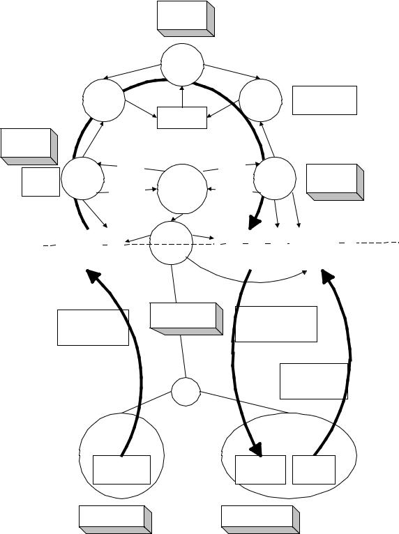
Figure 5-17. USB Full-speed Isochronous Application
70
Universal Serial Bus Specification Revision 2.0
Figure 5-17 shows a typical round trip path of information from a microphone as an input device to a speaker as an output device. The clocks, packets, and buffering involved are also shown. Figure 5-17 will be explored in more detail in the following sections.
The focus of this example is to identify the differences introduced by the USB compared to the previous non-USB example. The differences are in the areas of buffering, synchronization given the existence of a USB bus clock, and delay. The client software above the device drivers can be unaffected in most cases.
5.12.3 Clock Synchronization
In order for isochronous data to be manipulated reliably, the three clocks identified above must be synchronized in some fashion. If the clocks are not synchronized, several clock-to-clock attributes can be present that can be undesirable:
•Clock Drift: Two clocks that are nominally running at the same rate can, in fact, have implementation differences that result in one clock running faster or slower than the other over long periods of time. If uncorrected, this variation of one clock compared to the other can lead to having too much or too little data when data is expected to always be present at the time required.
•Clock Jitter: A clock may vary its frequency over time due to changes in temperature, etc. This may also alter when data is actually delivered compared to when it is expected to be delivered.
•Clock-to-clock Phase Differences: If two clocks are not phase locked, different amounts of data may be available at different points in time as the beat frequency of the clocks cycle out over time. This can lead to quantization/sampling related artifacts.
The bus clock provides a central clock with which USB hardware devices and software can synchronize to one degree or another. However, the software will, in general, not be able to phaseor frequency-lock precisely to the bus clock given the current support for “real time-like” operating system scheduling support in most PC operating systems. Software running in the host can, however, know that data moved over the USB is packetized. For isochronous transfer types, a unit of data is moved exactly once per (micro)frame and the (micro)frame clock is reasonably precise. Providing the software with this information allows it to adjust the amount of data it processes to the actual (micro)frame time that has passed.
Note: For high-speed high-bandwidth endpoints, the data exchanged in the two or three transactions per microframe is still considered to belong to the same “single packet.” The large amount of data per packet is split into two or three transactions only for bus efficiency reasons.
5.12.4 Isochronous Devices
The USB includes a framework for isochronous devices that defines synchronization types, how isochronous endpoints provide data rate feedback, and how they can be connected together. Isochronous devices include sampled analog devices (for example, audio and telephony devices) and synchronous data devices. Synchronization type classifies an endpoint according to its capability to synchronize its data rate to the data rate of the endpoint to which it is connected. Feedback is provided by indicating accurately what the required data rate is, relative to the SOF frequency. The ability to make connections depends on the quality of connection that is required, the endpoint synchronization type, and the capabilities of the host application that is making the connection. Additional device class-specific information may be required, depending on the application.
Note: The term “data” is used very generally, and may refer to data that represents sampled analog information (like audio), or it may be more abstract information. “Data rate” refers to the rate at which analog information is sampled, or the rate at which data is clocked.
71

Universal Serial Bus Specification Revision 2.0
The following information is required in order to determine how to connect isochronous endpoints:
•Synchronization type:
−Asynchronous: Unsynchronized, although sinks provide data rate feedback
−Synchronous: Synchronized to the USB’s SOF
−Adaptive: Synchronized using feedback or feedforward data rate information
•Available data rates
•Available data formats
Synchronization type and data rate information are needed to determine if an exact data rate match exists between source and sink, or if an acceptable conversion process exists that would allow the source to be connected to the sink. It is the responsibility of the application to determine whether the connection can be supported within available processing resources and other constraints (like delay). Specific USB device classes define how to describe synchronization type and data rate information.
Data format matching and conversion is also required for a connection, but it is not a unique requirement for isochronous connections. Details about format conversion can be found in other documents related to specific formats.
5.12.4.1 Synchronization Type
Three distinct synchronization types are defined. Table 5-12 presents an overview of endpoint synchronization characteristics for both source and sink endpoints. The types are presented in order of increasing capability.
Table 5-12. Synchronization Characteristics
|
|
Source |
Sink |
|
|
|
|
|
Asynchronous |
Free running Fs |
Free running Fs |
|
|
Provides implicit feedforward (data |
Provides explicit feedback (isochronous |
|
|
stream) |
pipe) |
|
|
|
|
|
Synchronous |
Fs locked to SOF |
Fs locked to SOF |
|
|
Uses implicit feedback (SOF) |
Uses implicit feedback (SOF) |
|
|
|
|
|
Adaptive |
Fs locked to sink |
Fs locked to data flow |
|
|
Uses explicit feedback (isochronous pipe) |
Uses implicit feedforward (data stream) |
|
|
|
|
5.12.4.1.1 Asynchronous
Asynchronous endpoints cannot synchronize to SOF or any other clock in the USB domain. They source or sink an isochronous data stream at either a fixed data rate (single-frequency endpoints), a limited number of data rates (32 kHz, 44.1 kHz, 48 kHz, …), or a continuously programmable data rate. If the data rate is programmable, it is set during initialization of the isochronous endpoint. Asynchronous devices must report their programming capabilities in the class-specific endpoint descriptor as described in their device class specification. The data rate is locked to a clock external to the USB or to a free-running internal clock. These devices place the burden of data rate matching elsewhere in the USB environment. Asynchronous source endpoints carry their data rate information implicitly in the number of samples they produce per
72