

usb_2.0_english
.pdfUniversal Serial Bus Specification Revision 2.0
3.3Feature List
The USB Specification provides a selection of attributes that can achieve multiple price/performance integration points and can enable functions that allow differentiation at the system and component level. Features are categorized by the following benefits:
Easy to use for end user
•Single model for cabling and connectors
•Electrical details isolated from end user (e.g., bus terminations)
•Self-identifying peripherals, automatic mapping of function to driver and configuration
•Dynamically attachable and reconfigurable peripherals
Wide range of workloads and applications
•Suitable for device bandwidths ranging from a few kb/s to several hundred Mb/s
•Supports isochronous as well as asynchronous transfer types over the same set of wires
•Supports concurrent operation of many devices (multiple connections)
•Supports up to 127 physical devices
•Supports transfer of multiple data and message streams between the host and devices
•Allows compound devices (i.e., peripherals composed of many functions)
•Lower protocol overhead, resulting in high bus utilization
Isochronous bandwidth
•Guaranteed bandwidth and low latencies appropriate for telephony, audio, video, etc.
Flexibility
•Supports a wide range of packet sizes, which allows a range of device buffering options
•Allows a wide range of device data rates by accommodating packet buffer size and latencies
•Flow control for buffer handling is built into the protocol
Robustness
•Error handling/fault recovery mechanism is built into the protocol
•Dynamic insertion and removal of devices is identified in user-perceived real-time
•Supports identification of faulty devices
Synergy with PC industry
•Protocol is simple to implement and integrate
•Consistent with the PC plug-and-play architecture
•Leverages existing operating system interfaces
13
Universal Serial Bus Specification Revision 2.0
Low-cost implementation
•Low-cost subchannel at 1.5 Mb/s
•Optimized for integration in peripheral and host hardware
•Suitable for development of low-cost peripherals
•Low-cost cables and connectors
•Uses commodity technologies
Upgrade path
•Architecture upgradeable to support multiple USB Host Controllers in a system
14
Universal Serial Bus Specification Revision 2.0
Chapter 4
Architectural Overview
This chapter presents an overview of the Universal Serial Bus (USB) architecture and key concepts. The USB is a cable bus that supports data exchange between a host computer and a wide range of simultaneously accessible peripherals. The attached peripherals share USB bandwidth through a hostscheduled, token-based protocol. The bus allows peripherals to be attached, configured, used, and detached while the host and other peripherals are in operation.
Later chapters describe the various components of the USB in greater detail.
4.1 USB System Description
A USB system is described by three definitional areas:
•USB interconnect
•USB devices
•USB host
The USB interconnect is the manner in which USB devices are connected to and communicate with the host. This includes the following:
•Bus Topology: Connection model between USB devices and the host.
•Inter-layer Relationships: In terms of a capability stack, the USB tasks that are performed at each layer in the system.
•Data Flow Models: The manner in which data moves in the system over the USB between producers and consumers.
•USB Schedule: The USB provides a shared interconnect. Access to the interconnect is scheduled in order to support isochronous data transfers and to eliminate arbitration overhead.
USB devices and the USB host are described in detail in subsequent sections.
15
Universal Serial Specification Revision 2.0
4.1.1 Bus Topology
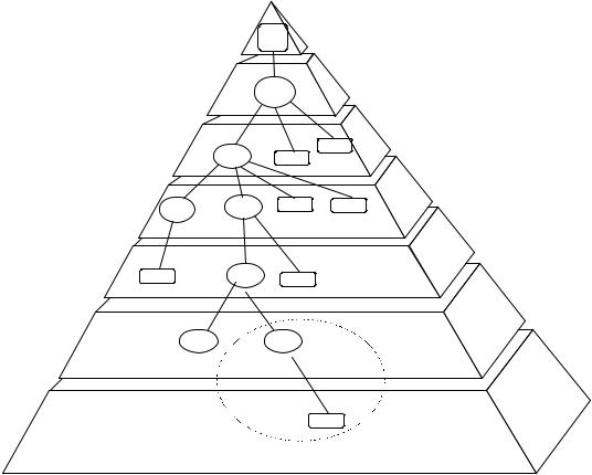
The USB connects USB devices with the USB host. The USB physical interconnect is a tiered star topology. A hub is at the center of each star. Each wire segment is a point-to-point connection between the host and a hub or function, or a hub connected to another hub or function. Figure 4-1 illustrates the topology of the USB.
Due to timing constraints allowed for hub and cable propagation times, the maximum number of tiers allowed is seven (including the root tier). Note that in seven tiers, five non-root hubs maximum can be supported in a communication path between the host and any device. A compound device (see Figure 4-1) occupies two tiers; therefore, it cannot be enabled if attached at tier level seven. Only functions can be enabled in tier seven.
Host
RootHub
Hub 1
Host (Tier 1)
Tier 2
Tier 3
Func
Hub 2 |
Func |
Tier 4
Hub 3 |
Hub 4 |
Func |
Func |
|
|
||
|
|
|
|
Func |
Hub 5 |
Func |
|
|
|
Tier 5
Tier 6
Compound Device
Hub 6 |
Hub 7 |
Tier 7
Func
Figure 4-1. Bus Topology
4.1.1.1 USB Host
There is only one host in any USB system. The USB interface to the host computer system is referred to as the Host Controller. The Host Controller may be implemented in a combination of hardware, firmware, or software. A root hub is integrated within the host system to provide one or more attachment points.
Additional information concerning the host may be found in Section 4.9 and in Chapter 10.
16
Universal Serial Bus Specification Revision 2.0
4.1.1.2 USB Devices
USB devices are one of the following:
•Hubs, which provide additional attachment points to the USB
•Functions, which provide capabilities to the system, such as an ISDN connection, a digital joystick, or speakers
USB devices present a standard USB interface in terms of the following:
•Their comprehension of the USB protocol
•Their response to standard USB operations, such as configuration and reset
•Their standard capability descriptive information
Additional information concerning USB devices may be found in Section 4.8 and in Chapter 9.
4.2 Physical Interface
The physical interface of the USB is described in the electrical (Chapter 7) and mechanical (Chapter 6) specifications for the bus.
4.2.1 Electrical
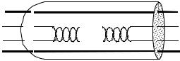
The USB transfers signal and power over a four-wire cable, shown in Figure 4-2. The signaling occurs over two wires on each point-to-point segment.
There are three data rates:
•The USB high-speed signaling bit rate is 480 Mb/s.
•The USB full-speed signaling bit rate is 12 Mb/s.
•A limited capability low-speed signaling mode is also defined at 1.5 Mb/s.
USB 2.0 host controllers and hubs provide capabilities so that full-speed and low-speed data can be transmitted at high-speed between the host controller and the hub, but transmitted between the hub and the device at full-speed or low-speed. This capability minimizes the impact that full-speed and low-speed devices have upon the bandwidth available for high-speed devices.
The low-speed mode is defined to support a limited number of low-bandwidth devices, such as mice, because more general use would degrade bus utilization.
The clock is transmitted, encoded along with the differential data. The clock encoding scheme is NRZI with bit stuffing to ensure adequate transitions. A SYNC field precedes each packet to allow the receiver(s) to synchronize their bit recovery clocks.
VBUS |
|
VBUS |
D+ |
... |
D+ |
D- |
... |
D- |
GND |
|
|
|
GND |
|
|
|
|
|
Figure 4-2. USB Cable |
|
17
Universal Serial Specification Revision 2.0
The cable also carries VBUS and GND wires on each segment to deliver power to devices. VBUS is nominally +5 V at the source. The USB allows cable segments of variable lengths, up to several meters, by choosing the appropriate conductor gauge to match the specified IR drop and other attributes such as device power budget and cable flexibility. In order to provide guaranteed input voltage levels and proper termination impedance, biased terminations are used at each end of the cable. The terminations also permit the detection of attach and detach at each port and differentiate between high/full-speed and low-speed devices.
4.2.2 Mechanical
The mechanical specifications for cables and connectors are provided in Chapter 6. All devices have an upstream connection. Upstream and downstream connectors are not mechanically interchangeable, thus eliminating illegal loopback connections at hubs. The cable has four conductors: a twisted signal pair of standard gauge and a power pair in a range of permitted gauges. The connector is four-position, with shielded housing, specified robustness, and ease of attach-detach characteristics.
4.3 Power
The specification covers two aspects of power:
•Power distribution over the USB deals with the issues of how USB devices consume power provided by the host over the USB.
•Power management deals with how the USB System Software and devices fit into the host-based power management system.
4.3.1 Power Distribution
Each USB segment provides a limited amount of power over the cable. The host supplies power for use by USB devices that are directly connected. In addition, any USB device may have its own power supply. USB devices that rely totally on power from the cable are called bus-powered devices. In contrast, those that have an alternate source of power are called self-powered devices. A hub also supplies power for its connected USB devices. The architecture permits bus-powered hubs within certain constraints of topology that are discussed later in Chapter 11.
4.3.2 Power Management
A USB host may have a power management system that is independent of the USB. The USB System Software interacts with the host’s power management system to handle system power events such as suspend or resume. Additionally, USB devices typically implement additional power management features that allow them to be power managed by system software.
The power distribution and power management features of the USB allow it to be designed into powersensitive systems such as battery-based notebook computers.
4.4 Bus Protocol
The USB is a polled bus. The Host Controller initiates all data transfers.
Most bus transactions involve the transmission of up to three packets. Each transaction begins when the Host Controller, on a scheduled basis, sends a USB packet describing the type and direction of transaction, the USB device address, and endpoint number. This packet is referred to as the “token packet.” The USB device that is addressed selects itself by decoding the appropriate address fields. In a given transaction, data is transferred either from the host to a device or from a device to the host. The direction of data transfer is specified in the token packet. The source of the transaction then sends a data packet or indicates it has no
18
Universal Serial Bus Specification Revision 2.0
data to transfer. The destination, in general, responds with a handshake packet indicating whether the transfer was successful.
Some bus transactions between host controllers and hubs involve the transmission of four packets. These types of transactions are used to manage the data transfers between the host and full-/low- speed devices.
The USB data transfer model between a source or destination on the host and an endpoint on a device is referred to as a pipe. There are two types of pipes: stream and message. Stream data has no USB-defined structure, while message data does. Additionally, pipes have associations of data bandwidth, transfer service type, and endpoint characteristics like directionality and buffer sizes. Most pipes come into existence when a USB device is configured. One message pipe, the Default Control Pipe, always exists once a device is powered, in order to provide access to the device’s configuration, status, and control information.
The transaction schedule allows flow control for some stream pipes. At the hardware level, this prevents buffers from underrun or overrun situations by using a NAK handshake to throttle the data rate. When NAKed, a transaction is retried when bus time is available. The flow control mechanism permits the construction of flexible schedules that accommodate concurrent servicing of a heterogeneous mix of stream pipes. Thus, multiple stream pipes can be serviced at different intervals and with packets of different sizes.
4.5 Robustness
There are several attributes of the USB that contribute to its robustness:
•Signal integrity using differential drivers, receivers, and shielding
•CRC protection over control and data fields
•Detection of attach and detach and system-level configuration of resources
•Self-recovery in protocol, using timeouts for lost or corrupted packets
•Flow control for streaming data to ensure isochrony and hardware buffer management
•Data and control pipe constructs for ensuring independence from adverse interactions between functions
4.5.1 Error Detection
The core bit error rate of the USB medium is expected to be close to that of a backplane and any glitches will very likely be transient in nature. To provide protection against such transients, each packet includes error protection fields. When data integrity is required, such as with lossless data devices, an error recovery procedure may be invoked in hardware or software.
The protocol includes separate CRCs for control and data fields of each packet. A failed CRC is considered to indicate a corrupted packet. The CRC gives 100% coverage on singleand double-bit errors.
4.5.2 Error Handling
The protocol allows for error handling in hardware or software. Hardware error handling includes reporting and retry of failed transfers. A USB Host Controller will try a transmission that encounters errors up to three times before informing the client software of the failure. The client software can recover in an implementation-specific way.
4.6 System Configuration
The USB supports USB devices attaching to and detaching from the USB at any time. Consequently, system software must accommodate dynamic changes in the physical bus topology.
19
Universal Serial Specification Revision 2.0
4.6.1 Attachment of USB Devices
All USB devices attach to the USB through ports on specialized USB devices known as hubs. Hubs have status bits that are used to report the attachment or removal of a USB device on one of its ports. The host queries the hub to retrieve these bits. In the case of an attachment, the host enables the port and addresses the USB device through the device’s control pipe at the default address.
The host assigns a unique USB address to the device and then determines if the newly attached USB device is a hub or a function. The host establishes its end of the control pipe for the USB device using the assigned USB address and endpoint number zero.
If the attached USB device is a hub and USB devices are attached to its ports, then the above procedure is followed for each of the attached USB devices.
If the attached USB device is a function, then attachment notifications will be handled by host software that is appropriate for the function.
4.6.2 Removal of USB Devices
When a USB device has been removed from one of a hub’s ports, the hub disables the port and provides an indication of device removal to the host. The removal indication is then handled by appropriate USB System Software. If the removed USB device is a hub, the USB System Software must handle the removal of both the hub and of all of the USB devices that were previously attached to the system through the hub.
4.6.3 Bus Enumeration
Bus enumeration is the activity that identifies and assigns unique addresses to devices attached to a bus. Because the USB allows USB devices to attach to or detach from the USB at any time, bus enumeration is an on-going activity for the USB System Software. Additionally, bus enumeration for the USB also includes the detection and processing of removals.
4.7 Data Flow Types
The USB supports functional data and control exchange between the USB host and a USB device as a set of either uni-directional or bi-directional pipes. USB data transfers take place between host software and a particular endpoint on a USB device. Such associations between the host software and a USB device endpoint are called pipes. In general, data movement though one pipe is independent from the data flow in any other pipe. A given USB device may have many pipes. As an example, a given USB device could have an endpoint that supports a pipe for transporting data to the USB device and another endpoint that supports a pipe for transporting data from the USB device.
The USB architecture comprehends four basic types of data transfers:
•Control Transfers: Used to configure a device at attach time and can be used for other device-specific purposes, including control of other pipes on the device.
•Bulk Data Transfers: Generated or consumed in relatively large and bursty quantities and have wide dynamic latitude in transmission constraints.
•Interrupt Data Transfers: Used for timely but reliable delivery of data, for example, characters or coordinates with human-perceptible echo or feedback response characteristics.
•Isochronous Data Transfers: Occupy a prenegotiated amount of USB bandwidth with a prenegotiated delivery latency. (Also called streaming real time transfers).
A pipe supports only one of the types of transfers described above for any given device configuration. The USB data flow model is described in more detail in Chapter 5.
20
Universal Serial Bus Specification Revision 2.0
4.7.1 Control Transfers
Control data is used by the USB System Software to configure devices when they are first attached. Other driver software can choose to use control transfers in implementation-specific ways. Data delivery is lossless.
4.7.2 Bulk Transfers
Bulk data typically consists of larger amounts of data, such as that used for printers or scanners. Bulk data is sequential. Reliable exchange of data is ensured at the hardware level by using error detection in hardware and invoking a limited number of retries in hardware. Also, the bandwidth taken up by bulk data can vary, depending on other bus activities.
4.7.3 Interrupt Transfers
A limited-latency transfer to or from a device is referred to as interrupt data. Such data may be presented for transfer by a device at any time and is delivered by the USB at a rate no slower than is specified by the device.
Interrupt data typically consists of event notification, characters, or coordinates that are organized as one or more bytes. An example of interrupt data is the coordinates from a pointing device. Although an explicit timing rate is not required, interactive data may have response time bounds that the USB must support.
4.7.4 Isochronous Transfers
Isochronous data is continuous and real-time in creation, delivery, and consumption. Timing-related information is implied by the steady rate at which isochronous data is received and transferred. Isochronous data must be delivered at the rate received to maintain its timing. In addition to delivery rate, isochronous data may also be sensitive to delivery delays. For isochronous pipes, the bandwidth required is typically based upon the sampling characteristics of the associated function. The latency required is related to the buffering available at each endpoint.
A typical example of isochronous data is voice. If the delivery rate of these data streams is not maintained, drop-outs in the data stream will occur due to buffer or frame underruns or overruns. Even if data is delivered at the appropriate rate by USB hardware, delivery delays introduced by software may degrade applications requiring real-time turn-around, such as telephony-based audio conferencing.
The timely delivery of isochronous data is ensured at the expense of potential transient losses in the data stream. In other words, any error in electrical transmission is not corrected by hardware mechanisms such as retries. In practice, the core bit error rate of the USB is expected to be small enough not to be an issue. USB isochronous data streams are allocated a dedicated portion of USB bandwidth to ensure that data can be delivered at the desired rate. The USB is also designed for minimal delay of isochronous data transfers.
4.7.5 Allocating USB Bandwidth
USB bandwidth is allocated among pipes. The USB allocates bandwidth for some pipes when a pipe is established. USB devices are required to provide some buffering of data. It is assumed that USB devices requiring more bandwidth are capable of providing larger buffers. The goal for the USB architecture is to ensure that buffering-induced hardware delay is bounded to within a few milliseconds.
The USB’s bandwidth capacity can be allocated among many different data streams. This allows a wide range of devices to be attached to the USB. Further, different device bit rates, with a wide dynamic range, can be concurrently supported.
The USB Specification defines the rules for how each transfer type is allowed access to the bus.
21
Universal Serial Specification Revision 2.0
4.8 USB Devices
USB devices are divided into device classes such as hub, human interface, printer, imaging, or mass storage device. The hub device class indicates a specially designated USB device that provides additional USB attachment points (refer to Chapter 11). USB devices are required to carry information for selfidentification and generic configuration. They are also required at all times to display behavior consistent with defined USB device states.
4.8.1 Device Characterizations
All USB devices are accessed by a USB address that is assigned when the device is attached and enumerated. Each USB device additionally supports one or more pipes through which the host may communicate with the device. All USB devices must support a specially designated pipe at endpoint zero to which the USB device’s USB control pipe will be attached. All USB devices support a common access mechanism for accessing information through this control pipe.
Associated with the control pipe at endpoint zero is the information required to completely describe the USB device. This information falls into the following categories:
•Standard: This is information whose definition is common to all USB devices and includes items such as vendor identification, device class, and power management capability. Device, configuration, interface, and endpoint descriptions carry configuration-related information about the device. Detailed information about these descriptors can be found in Chapter 9.
•Class: The definition of this information varies, depending on the device class of the USB device.
•USB Vendor: The vendor of the USB device is free to put any information desired here. The format, however, is not determined by this specification.
Additionally, each USB device carries USB control and status information.
4.8.2 Device Descriptions
Two major divisions of device classes exist: hubs and functions. Only hubs have the ability to provide additional USB attachment points. Functions provide additional capabilities to the host.
4.8.2.1 Hubs
Hubs are a key element in the plug-and-play architecture of the USB. Figure 4-3 shows a typical hub. Hubs serve to simplify USB connectivity from the user’s perspective and provide robustness at relatively low cost and complexity.
Hubs are wiring concentrators and enable the multiple attachment characteristics of the USB. Attachment points are referred to as ports. Each hub converts a single attachment point into multiple attachment points. The architecture supports concatenation of multiple hubs.
The upstream port of a hub connects the hub towards the host. Each of the downstream ports of a hub allows connection to another hub or function. Hubs can detect attach and detach at each downstream port and enable the distribution of power to downstream devices. Each downstream port can be individually enabled and attached to either high-, fullor low-speed devices.
A USB 2.0 hub consists of three portions: the Hub Controller, the Hub Repeater, and the Transaction Translator. The Hub Repeater is a protocol-controlled switch between the upstream port and downstream ports. It also has hardware support for reset and suspend/resume signaling. The Host Controller provides the communication to/from the host. Hub-specific status and control commands permit the host to configure a hub and to monitor and control its ports. The Transaction Translator provides the mechanisms that support full-/low-speed devices behind the hub, while transmitting all device data between the host and the hub at high-speed.
22