

Книги по МРТ КТ на английском языке / MRI for Orthopaedic Surgeons Khanna ed 2010
.pdf150 III Lower Extremity
A
B
Fig. 7.5 Zone classification. (A) An artist’s depiction of the left and right hemipelves. The acetabulum has been subdivided into six zones: 1, anterior-inferior; 2, anterior-superior; 3, central superior; 4, posterior-superior; 5, posterior-inferior; and 6, acetabular notch. (B) An artist’s depiction of the left and right proximal femurs. (Left) The frontal view of the femoral head is divided into six zones around the acetabular fossa (there is a dotted line around the ligamentum teres [LT]): 1, anterior-inferior; 2, anterior-superior; 3, central
anatomic zones of labral vascularity. They reported that cadaveric specimens have relatively avascular hip labra, with no statistically significant (p >.05) di erences among the anterior, superior, posterior, or inferior labral lesions, or in torn versus
superior; 4, posterior-superior; 5, posterior-inferior; and 6, area around the ligamentum teres. (Right) The superior view shows the three subdivisions of zones 2, 3, and 4: medial (M), superior (S), and lateral (L). (From Ilizaliturri VM Jr, Byrd JWT, Sampson TG, et al. A geographic zone method to describe intra-articular pathology in hip arthroscopy: cadaveric study and preliminary report. Arthroscopy 2008;24:534–539. Reprinted by permission.)
intact specimens. However, slightly increased vascularity was seen on the capsular compared with the articular side, suggesting that the vascularity usually is supplied by the capsule. Those authors also noted that all labral tears were associated

7 The Hip 151
with increased microvascularity at the labral base, adjacent to the attachment of bone. Such studies have important future implications for labral surgery in terms of determining the type and location of tears that would be amenable to successful repair, as opposed to arthroscopic debridement.
MRI evaluation of the postoperative labrum is similar to that of the postoperative meniscus in the knee. Because labral debridement causes a persistent intralabral signal secondary to abnormally mobile water in the degenerative fibrocartilage, the presence of abnormal signal alone should not serve as a primary indicator of a re-tear. The most reliable indicator of a re-tear of a labral remnant is the presence of a displaced fragment.
Stress Fractures
Stress fractures, which result from cyclic mechanical stress, can be subdivided into one of two groups: fatigue or insufficiency. Military recruits and athletes are more susceptible than the general population to fatigue fractures, given that they occur in normal bone that is exposed to a repetitive mechanical overload that overwhelms the normal remodeling process.18 Insu ciency fractures occur more commonly in the elderly secondary to osteoporosis, osteomalacia, or other processes that weaken the bone, permitting osseous failure to occur after fewer loading cycles than in normal bone. Insu ciency fractures in the athletic population have also been described in female athletes, in association with the female athletic triad.19 Stress fractures can occur on the compression or the tension side of the femoral neck.20 Compression stress fractures are more common and begin at the inferior cortex of the femoral neck. Tension stress fractures begin in the superior cortex, have a greater propensity to displace, and thus require more aggressive treatment. A fracture line with a benign periosteal reaction may be visualized on conventional radiography or CT, and bone scintigraphy may be sensitive but not specific for the diagnosis of femoral neck stress fracture. However, MRI is sensitive and specific to the presence of underlying bone marrow lesions, and a linear fracture line associated with the preservation of fatty marrow should be sought to confirm the diagnosis of a stress fracture.20,21 Fat-suppressed or STIR coronal images show a linear pattern of increased signal intensity, which is compatible with an acute or subacute fracture (Fig. 7.6). MRI is also useful for excluding underlying lesions, such as a tumor, or marrow disorders that may be the cause of a pathologic stress fracture.
Traumatic Posterior Subluxation/
Dislocation/Lateral Impaction
A traumatic posterior hip dislocation most commonly occurs as a result of a motor vehicle accident when the hip and knee are flexed and the knee impacts on the dashboard, producing
Fig. 7.6 A coronal fat-suppressed image obtained with a body coil technique, showing increased signal intensity (arrow) surrounding a stress fracture at the medial aspect of the left femoral neck. (© 2009 Hospital for Special Surgery, New York, NY.)
a posteriorly directed force on the hip. In the acute setting, MRI may aid in the diagnosis of the following22,23:
•Femoral head contusions
•Labral disruptions
•Sciatic nerve injury
•Intraarticular fragments
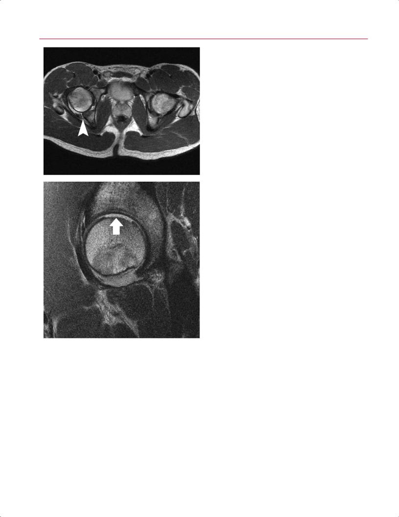
Hip subluxation usually has a more subtle presentation than does hip dislocation because of its lower energy mechanism of injury, such as a fall on a flexed hip and knee; however, subluxation is a potentially devastating injury that may be misdiagnosed as a simple hip strain or sprain. Traumatic posterior subluxation events in football or other high-level athletic activities may cause symptomatic cartilage-shear- ing injuries and labral tears, but they are not associated with radiographic documentation of a dislocation.24 Depending on the degree of force applied to the hip at the time of translation, the posterior labrum or wall may be displaced and/or combined with anterior labral tears, disruption of the iliofemoral ligament, and parafoveal cartilage shearing injuries; the latter two typically are sustained at the time of reduction (Fig. 7.7). MRI is also a useful tool for detecting the complication of osteonecrosis and for assisting in the determination of when athletes may return safely to sports activity24,25 (see Osteonecrosis, below). Byrd26 described a lateral impaction injury as a direct blow to the greater trochanter, resulting in isolated traumatic chondral injuries in young, physically fit individuals as a consequence of sports
152 III Lower Extremity
Fig. 7.7 Posterior hip subluxation. Axial body coil (A) and sagittal surface coil (B,C) FSE images of the hip in an 18-year-old patient with sequelae of posterior hip subluxation. An intact right posterior hip capsule is seen, attached to a posterior wall fracture (A, arrowhead), and associated with a large full-thickness chondral shear injury of the femoral head (B, arrow). Cartilaginous debris (C, arrow) is seen within the anteroinferior dependent recess of the joint. (From Shindle MK, Foo LF, Kelly BT, et al. Magnetic resonance imaging of cartilage in the athlete: current techniques and spectrum of disease. J Bone Joint Surg Am 2006;88:27–46. Reprinted by permission. © 2009 Hospital for Special Surgery, New York, NY.)
A
B 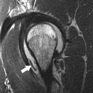 C
C
or activity. MRI is useful in this scenario for determining the extent of chondral damage and for evaluating the presence of osteochondral loose bodies.
Greater Trochanteric Pain Syndrome
Greater trochanteric pain syndrome is a common regional pain syndrome that encompasses greater trochanteric bursitis and tears/tendinosis of the gluteus medius and minimus. The major clinical findings are nonspecific, usually with tenderness localized to the lateral aspect of the hip or thigh. Clinically, distinguishing isolated bursal pathologic changes from tendon abnormalities or other soft-tissue lesions is difficult; therefore, the di erential diagnosis is quite broad and
requires consideration of articular, periarticular, and distant processes as a source of lateral hip pain.27
Trochanteric Bursitis
The surface of the greater trochanter has four distinct facets:
•Anterior
•Posterior
•Lateral
•Superoposterior
The overlying trochanteric bursa is composed of three discrete components27:

|
7 The Hip 153 |
||
|
|
|
|
• Subgluteus maximus bursa |
show hyperintensity with abnormal morphology of the torn |
||
• Subgluteus medius bursa |
tendon fibers, and full-thickness tears show a fluid-filled gap |
||
• Subgluteus minimus bursa |
with a retracted tendon (Fig. 7.8B). Some patients have “in- |
||
Excessive friction from the overlying ITB is the most likely |
tractable” complaints of trochanteric bursitis despite multi- |
||
ple injections and nonoperative treatment. For such patients, |
|||
etiology, but trochanteric bursitis often is a manifestation of |
|||
MRI may be diagnostic for a gluteus medius or minimus rup- |
|||
underlying abductor tendon pathology. Thus, the presence of |
|||
ture.32 The MRI appearance of abductor tendinosis or tears, |
|||
trochanteric bursitis should prompt careful attention to the |
|||
which includes alterations in tendon caliber and signal, is |
|||
underlying abductor tendons. Fat-suppressed MR sequences, |
|||
the same as that in other locations. |
|||
particularly coronal and axial images, should be evaluated |
|||
|
|
||
for bursal distention with high signal intensity. |
|
|
|
Abductor Tears
The gluteus medius inserts onto the superoposterior and lateral facets, and the gluteus minimus inserts onto the anterior facet of the greater trochanter. MRI evaluation of the hip in patients more than 40 years old usually reveals several pathologic processes, including some degree of the following28,29:
•Cartilage degeneration
•Degenerative labral lesions
•Extracapsular abnormalities (including abductor or iliopsoas tendinosis)
Abductor tears have been termed the “rotator cu tears of the hip” and are highly prevalent in patients with osteoarthritis.30,31 Again, the coronal and axial sequences should be evaluated for the presence or absence of such tears. Greater trochanteric bursitis is usually indicated by increased signal on fat-suppressed images (Fig. 7.8A). Partial-thickness tears
Snapping Hip Syndrome (Coxa Saltans)
The snapping hip syndrome, or coxa saltans, is characterized by an audible or palpable snapping of the hip with flexion and extension of the hip, occasionally resulting in pain. The etiology of coxa saltans has been divided into three categories33:
•Intraarticular
•Internal (snapping of iliopsoas tendon against an osseous ridge)
•External (snapping of the ITB or gluteus maximus muscle over the greater trochanter)
It is important to accurately determine the source of the snapping so that the appropriate treatment can be given. MRI is useful for excluding other intraor extraarticular hip abnormalities, but its role in diagnosing coxa saltans is limited because of its lack of dynamic capabilities. With internal coxa saltans, fat-suppressed images may display a hyperintense iliopsoas bursa fluid. With external coxa saltans,
A
Fig. 7.8 Hip abductor tear. (A) A coronal fat-suppressed image of the hip showing a fluid-filled space that should be occupied by the left hip abductors, indicating a tear (arrow). (B) An FSE image showing
B
tendinosis of the gluteus medius tendon (arrow) with dehiscence of its insertion from the greater trochanter. (© 2009 Hospital for Special Surgery, New York, NY.)

154 III Lower Extremity
fat-suppressed images may show a hyperintense ITB, tro- |
are equivalent to muscle strains in the adult. During running |
|
chanteric bursa, and anterior border of the gluteus maximus. |
and jumping activities, the hamstring origins at the ischial |
|
Because of MRI’s lack of dynamic capabilities, dynamic so- |
tuberosity may be avulsed; these injuries have been referred |
|
nography of the hip is beneficial as an adjuvant to confirm the |
to as hurdler’s fractures.37 Apophyseal injuries of the pelvis |
|
diagnosis. |
may also involve the rectus femoris or sartorius muscles at |
|
|
the anteroinferior or anterosuperior iliac spines, respectively. |
|
Piriformis Syndrome |
In competitive sports that require kicking motions with ex- |
|
treme hip flexion, avulsions of the iliopsoas tendon o the |
||
|
||
The sciatic nerve exits the pelvis through the greater sci- |
lesser trochanter may be seen. |
|
atic notch, which is formed, in part, by the piriformis ten- |
The most commonly strained muscles around the hip |
|
don. Although variations exist, the nerve usually is located |
joint are the following: |
|
immediately anterior to the piriformis muscle. Irritation of |
• Hamstrings (biceps femoris, semimembranosus, and |
|
the piriformis musculotendinous unit can cause compres- |
||
semitendinosus) |
||
sion of the sciatic nerve, which in turn may cause pain and |
||
• Rectus femoris |
||
dysesthesias in the gluteal region or radicular-type symp- |
||
• Adductors |
||
toms.34 MRI may show an abnormal hypertrophic piriformis |
||
The adductor group is frequently involved, especially in |
||
muscle and/or hyperintensity of the sciatic nerve on fat- |
||
suppressed images or a variant course of the nerve through |
hockey, soccer, and football players; in those athletes, medial |
|
the piriformis muscle. There is usually a mass e ect, result- |
thigh or groin pain is the presenting complaint.36 The MRI |
|
ing in displacement of the muscle from anterior to poste- |
classification is based on the extent of disruption present: |
|
rior with a loss of normal muscle striations. There may be |
in general, on fat-suppressed images, muscle avulsions and |
|
e acement of fat in the greater sciatic foramen, and gluteal |
tears have high signal intensity in areas of hemorrhage or |
|
atrophy may be present.35 Neurophysiologic testing may be |
edema. First-degree strains have a minor degree of fiber dis- |
|
required to confirm the diagnosis.34 |
ruption and a “feathery” pattern of increased signal intensity |
|
|
on fat-suppressed T2-weighted images secondary to intersti- |
|
Muscle Strains |
tial edema and hemorrhage that extends into the adjacent |
|
muscle fascicles. Second-degree strains have a partial tear |
||
|
||
The most frequent injuries about the groin and hip are |
without retraction and often also have a hematoma at the |
|
muscle strains and tears. These injuries usually a ect the |
myotendinous junction. Third-degree strains have a com- |
|
myotendinous junction, which is the weakest point of the |
plete rupture of the myotendinous unit.38 Acute tendinous |
|
musculotendinous unit, but they may also occur via avul- |
avulsion injuries of the rectus femoris tendon at its origin |
|
sion at the osseous insertion or origin.36 Apophyseal avul- |
at the anterior inferior iliac spine can be seen. This injury |
|
sion injuries usually occur in the adolescent population and |
occurs most commonly after forceful extension of the hip35 |
|
|
(Fig. 7.9). Hamstring tears are usually partial-thickness, and |
|
|
the proximal long head of the biceps femoris is the most fre- |
|
|
quently injured structure, followed by the semitendinosus |
|
|
and semimembranosus muscles. Injuries usually occur at the |
|
|
musculotendinous junction with the characteristic feather- |
|
|
like edema pattern described above. |
Fig. 7.9 An axial FSE image obtained with a body coil technique, showing avulsion of the proximal portion of the rectus femoris from the left anterior inferior iliac spine (left arrow). A normal low signal tendinous insertion is seen on the right (right arrow). (© 2009 Hospital for Special Surgery, New York, NY)
■ Bone Marrow Abnormalities
Osteonecrosis
Osteonecrosis (also termed avascular necrosis or aseptic necrosis) of the femoral head is the cellular necrosis of the bone and bone marrow elements that compromise a part of or the entire femoral head. Osteonecrosis is the preferred term because it makes no reference to the pathophysiology of the disease. There are numerous predisposing causes, including the following39:
•Corticosteroid usage
•Collagen vascular disease
7 The Hip 155
|
activity. However, if there is evidence of osteonecrosis, pa- |
|
|
tients are at increased risk for subsequent collapse and joint |
|
|
degeneration.24 |
|
|
A limited MRI examination may be obtained for the de- |
|
|
tection of femoral head osteonecrosis and quantification of |
|
|
the size of the lesion in selected patients.48 Several methods |
|
|
have been proposed to measure the extent of osteonecro- |
|
|
sis for prognosis and treatment planning. La orgue et al49 |
|
|
measured the α angle on the coronal T1-weighted images, |
|
|
selecting the largest area of necrosis and determining the |
|
|
angle formed at the center of the femoral head. An angle of |
|
|
more than 75 degrees was considered to have a poor prog- |
|
|
nosis, and an angle of less than 46 degrees corresponded to |
|
|
a satisfactory clinical response. Koo and Kim50 measured the |
|
|
angle formed from the center of the femoral head on midcor- |
|
|
onal and midsagittal MR images to quantify the size of the |
|
|
lesion objectively. Cherian et al51 modified this method for |
|
|
quantifying the extent of osteonecrosis of the femoral head |
|
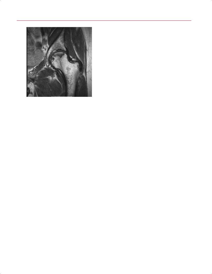
Fig. 7.10 A coronal FSE image of the left hip showing a region of os- |
by using the coronal and sagittal MR images with maximal |
|
teonecrosis at the weight-bearing surface of the femoral head with |
femoral head involvement. They concluded that that method |
|
a classic serpentine line of demarcation from the adjacent normal |
was a reproducible and reliable way of determining the ex- |
|
bone. (© 2009 Hospital for Special Surgery, New York, NY.) |
tent of osteonecrosis. |
|
|
A low percentage of involvement of the femoral head |
|
|
weight-bearing surface has been well correlated with a fa- |
|
• Dislocation of the hip |
vorable outcome in patients with early stages of the dis- |
|
ease49 and the unlikelihood of femoral head collapse after |
||
• Femoral neck fracture |
||
core decompressive surgery.52 In one study, femoral head |
||
• Hemoglobinopathies |
||
collapse did not occur when the MRI showed that less than |
||
MRI has been shown to be more sensitive than conven- |
||
25% of the weight-bearing surface was involved.52 However, |
||
tional radiography, nuclear scintigraphy, or CT for the early |
when more than 50% of the surface was involved, 87% of hips |
|
detection of osteonecrosis.40–43 Besides aiding in this early |
had femoral head collapse.52 |
|
detection, MRI is useful for di erentiating osteonecrosis |
MRI is also useful for identifying and localizing the ne- |
|
from other pathologic processes and for predicting the likeli- |
crotic lesion before performing a core decompression proce- |
|
hood of femoral head collapse.44,45 Osteonecrosis of the fem- |
dure. It is also not infrequent to see cartilage loss and geode |
|
oral head has a characteristic MRI appearance: a low-signal, |
formation on the acetabular side as a result of osteonecrosis |
|
crescent-shaped rim in a subchondral location that corre- |
of the femoral head.49 This finding is important because it |
|
sponds to the interface between normal and ischemic bone |
may change the treatment approach—for example, total hip |
|
(Fig. 7.10). A second rim of increased signal that is pathogno- |
replacement rather than femoral head resurfacing or core |
|
monic of osteonecrosis usually is present on fat-suppressed |
decompression. |
|
images.42,44 The presence of a band of low signal intensity |
|
|
on T1-weighted images or of the “double-line” sign on T2- |
Idiopathic Transient Osteoporosis |
|
weighted or fat-suppressed proton-density images are each |
|
|
reported to be an early specific sign of nontraumatic osteo- |
Idiopathic transient osteoporosis is a rare and often unrec- |
|
necrosis of the femoral head.42,43 The double-line sign, which |
ognized cause of hip pain that is usually seen healthy young |
|
appears as a low signal intensity peripheral line and a paral- |
adults. The condition most commonly a ects women in the |
|
lel inner line of high signal intensity, can be observed in up |
third trimester of pregnancy and middle-aged men. Symptoms |
|
to 80% of lesions.46 These MRI abnormalities represent the |
often present insidiously, with pain in the a ected hip, and then |
|
reactive interface between necrotic and viable bone.42,47 MRI |
progress to gait disturbance and functional disability. Transient |
|
may also show a joint e usion on fat-suppressed sequences. |
osteoporosis of the hip should be considered after more com- |
|
In the presence of a posterior hip subluxation, MRI is a |
mon causes of hip pain (such as infection, stress fractures, or |
|
useful tool for detecting osteonecrosis. In the acute setting, |
malignancy) are ruled out. Conventional radiographs usually |
|
MRI is not an accurate predictor of osteonecrosis, and a re- |
show focal osteopenia of the femoral head and neck with loss |
|
peat study is usually obtained at 6 weeks. If there is no evi- |
of cortical continuity, although this finding may be subtle and |
|
dence of osteonecrosis, patients may safely return to sports |
is frequently missed. Fat-suppressed MR images show di use |
156 III Lower Extremity
high signal intensity compatible with edema in the femoral |
However, subchondral fractures leading to femoral head col- |
|
head and proximal femoral neck and a small hip joint e usion, |
lapsehavebeenreported.46 Therefore,patientsshouldbetreated |
|
which are the classic findings of transient osteoporosis of the |
with protected weight bearing and monitored carefully with re- |
|
hip. However, this di use edema pattern may be related to a |
peat MRI until the edema is resolved and the clinical symptoms |
|
subtle subchondral fracture53,54 (Fig. 7.11). This entity can be |
subside. |
|
di erentiated from osteonecrosis of the hip, which shows signal |
|
|
changes at the weight-bearing surface of the femoral head and |
|
|
■ Degenerative Conditions |
||
is not as di use as that seen with transient osteoporosis of the |
||
hip. Most cases resolve spontaneously within 6 to 12 months. |
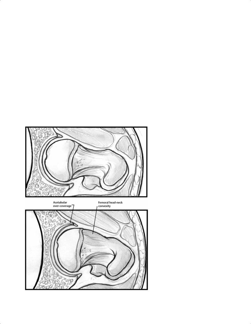
Femoroacetabular Impingement |
|
|
Femoroacetabular impingement is a well-described patho- |
|
|
logic condition that has been associated with predisposing |
|
|
factors such as the following55–59: |
|
|
• Slipped capital femoral epiphysis |
|
|
• Abnormal extension of the femoral head epiphysis |
|
|
• Acetabular retroversion |
|
|
Repetitive microtrauma from impingement during hip |
|
|
flexion and internal rotation leads to degeneration of the |
|
|
acetabular labrum and articular cartilage. This progressive |
|
|
degeneration and tearing of the labrum, as well as damage to |
|
|
the articular cartilage, predisposes patients to osteoarthri- |
|
|
tis.46,57,58,60,61 Femoroacetabular impingement is caused by |
|
|
two main types of mechanisms: “cam” and “pincer.” Most |
|
|
femoroacetabular impingement cases represent a combina- |
|
|
tion of both mechanisms62 (see Chapter 14) (Fig. 7.12). MRI |
|
|
is an excellent modality for femoroacetabular impingement |
|
|
because it permits early detection of the disease process |
|
|
and can identify labral tears, cartilage damage, subchondral |
|
A |
cysts, and underlying subtle anatomic variations of the fem- |
|
|
oral head–neck junction or acetabulum associated with cam |
|
|
or pincer impingement. |
|
|
The cam type involves shear forces created by the nons- |
|
|
pherical portion of the femoral head impinging on the ac- |
|
|
etabulum, resulting in a characteristic pattern of cartilage |
|
|
loss over the anterosuperior weight-bearing portion of the |
|
|
acetabulum and, eventually, possible tear or detachment of |
|
|
the principally uninvolved labrum56,58 (Fig. 7.13). MRI is an |
|
|
excellent modality for assessment of femoroacetabular im- |
|
|
pingement because it can detect subtle anatomic variations |
|
|
of the femoral head–neck junction, labral pathology, adjacent |
|
|
cartilage damage, and subchondral cysts. Typical findings on |
|
|
fat-suppressed images may include any of the following: |
|
|
• Intermediate-signal labral degeneration |
|
B |
• Labral tears with a hyperintense linear or di use sig- |
|
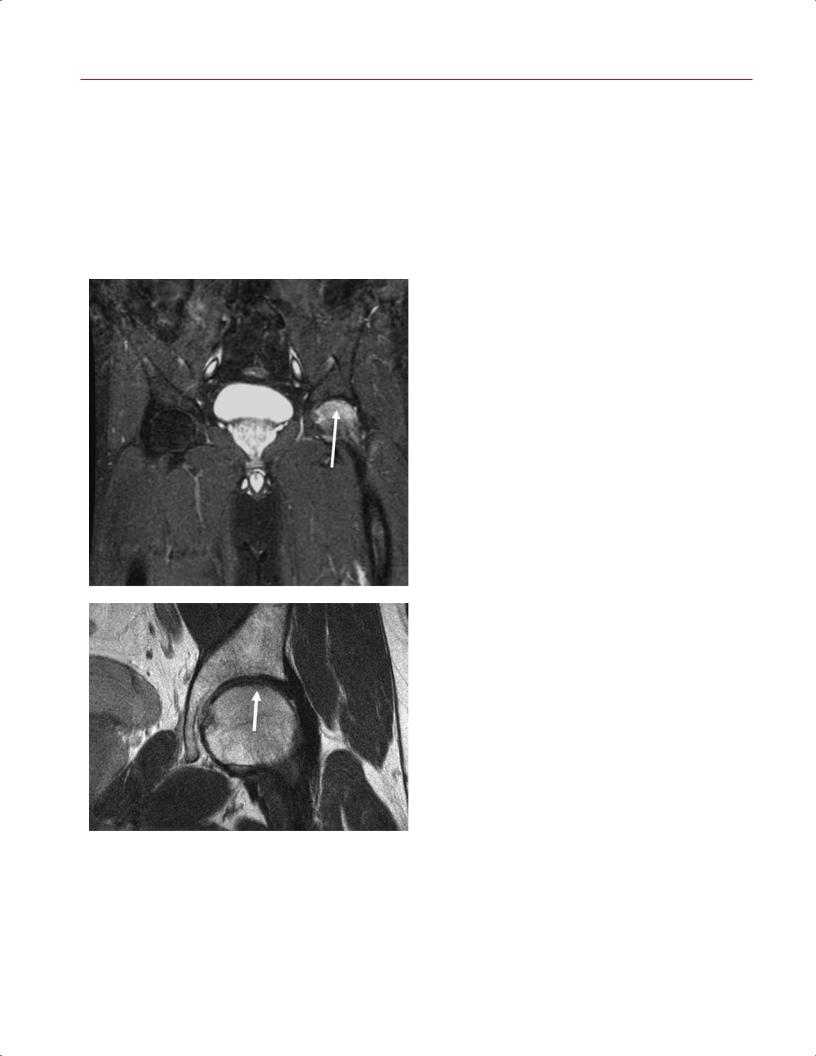
Fig. 7.11 Transient osteoporosis of the hip. (A) A coronal FSE image |
nal intensity |
|
• Defects or fissures in the articular cartilage |
||
with fat suppression showing di use and extensive high signal of the |
||
• Hyperintense femoral head/neck cysts |
||
left femoral head without a demarcated focus (arrow). Because there |
||
|
||
is no evidence of demarcation defining osteonecrosis, the diagnosis |
Typical findings on FSE sequences may include abnormal |
|
is consistent with transient osteoporosis of the hip. (B) Most cases of |
contour of the acetabular labrum and a cam lesion. De- |
|
transient osteoporosis actually represent subchondral femoral head |
||
creased o set of the femoral head–neck junction can be de- |
||
stress fractures, which can be appreciated on this coronal FSE image |
||
tected on conventional radiographs or MRI as a prominent |
||
(arrow). (© 2009 Hospital for Special Surgery, New York, NY) |
|
7 The Hip 157 |
||
lateral extension of the femoral head at the step-o to the |
The pincer type involves contact between a normal femo- |
|
|
adjacent femoral neck.46 Other features that can be present |
ral neck and an abnormal anterior acetabular rim secondary |
||
on MR images are the following: |
to acetabular retroversion or protrusion. In this setting, the |
||
• Congruent but nonspherical head |
acetabular labrum fails first, which leads to degeneration |
||
and eventual ossification, worsening the over-coverage (ret- |
|||
• Small head-to-neck ratio |
|||
roversion). In patients with a retroverted acetabulum, axial |
|||
• Short neck |
|||
MR images show increased coverage of the anterior femoral |
|||
As part of the multiplanar assessment of femoroacetabular |
|||
head.64 During flexion and internal rotation, the prominent |
|||
impingement, oblique axial MRI sequences can be help- |
anterolateral edge of the acetabulum leads to impingement |
||
ful in defining the abnormal osseous neck-shaft o set. |
and subsequent labral degeneration. Synovial fluid may pen- |
||
In those images, the segment prescription is parallel to |
etrate into the subchondral bone and lead to subchondral |
||
the neck-shaft angle of a coronal image, passing directly |
cyst formation.56,64,65 In addition, persistent anterior abut- |
||
through the center of the femoral head. The α angle, mea- |
ment can result in contre-coup cartilage lesions of the pos- |
||
sured according to the method of Nötzli et al,63 can help |
teroinferior acetabulum. Overall, the pincer type has limited |
||
define the anterior margin of the waist of the femoral neck |
chondral lesions compared with the deep chondral lesions |
||
(Fig. 7.14). |
associated with cam impingement.59,66 |
||
A
|
Fig. 7.12 Diagrammatic representation of (A) |
|
normal acetabulum and femur morphology and |
|
(B) combined femoroacetabular impingement |
|
with reduced head-neck o set (cam mechanism) |
|
and excessive anterior over-coverage (pincer |
B |
mechanism). |
158 III Lower Extremity
Osteoarthritis
Osteoarthritis is characterized by articular cartilage degenerative change with hip joint space narrowing; the incidence of this process increases with age. There are several conditions that lead to osteoarthritis, including the following46:
•Femoroacetabular impingement
•Previous slipped capital femoral epiphysis
•Developmental dysplasia of the hip
•Legg-Calvé-Perthes disease
•Trauma
•Other anatomic variants
A
The appearance of osteoarthritis on MR images is similar to that on conventional radiographs, including the following:
•Hypointense subchondral sclerosis of the femoral head and acetabulum
•Joint space narrowing
•Osteophyte formation
•Subchondral cysts
Osteoarthritis may also be associated with labral tears, paralabral cysts, synovitis, or osteonecrosis of the femoral head.67
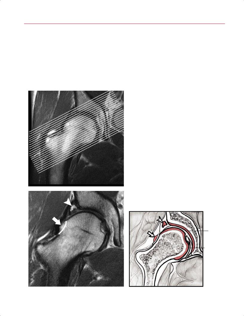
Fig. 7.13 FSE images and sketches of a 41-year-old patient with combined femoroacetabular impingement of the right hip.
(A) The segment prescription (© 2009 Hospital for Special Surgery, New York, NY). The coronal image (© 2009 Hospital for Special Surgery, New York, NY) (B) and associated artist’s sketch
(C) show a torn superior labrum (arrowhead on each) and a cam lesion at the neck–shaft junction (arrow on each). (Adapted from Shindle MK, Foo LF, Kelly BT, et al. Magnetic resonance imaging of cartilage in the athlete: current techniques and spectrum of disease. J Bone Joint Surg Am 2006;88:27–46. Adapted by permission.) (Continued on page 159)
Acetabular cartilage
Femoral head cartilage
B |
C |
7 The Hip 159
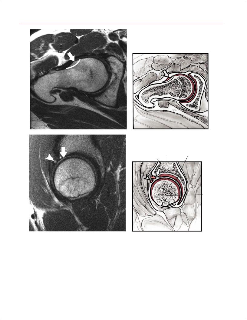
D |
E |
Acetabular |
Femoral head |
|
cartilage |
||
cartilage |
||
|
Acetabulum
Femoral head
F |
G |
Fig. 7.13 (Continued) The oblique axial view (© 2009 Hospital for Special Surgery, New York, NY) (D) and associated artist’s sketch
(E)(arrow on each) accentuate the osseous defect (cam lesion). The sagittal image (© 2009 Hospital for Special Surgery, New York, NY)
(F)and associated artist’s sketch (G) show full-thickness cartilage loss over the anterior acetabular dome (arrow on each) and partial-
thickness cartilage loss of the anterior femoral head (arrowhead on each). (Adapted from Shindle MK, Foo LF, Kelly BT, et al. Magnetic resonance imaging of cartilage in the athlete: current techniques and spectrum of disease. J Bone Joint Surg Am 2006;88:27–46. Adapted by permission.)