

Книги по МРТ КТ на английском языке / MRI for Orthopaedic Surgeons Khanna ed 2010
.pdf190 III Lower Extremity
A 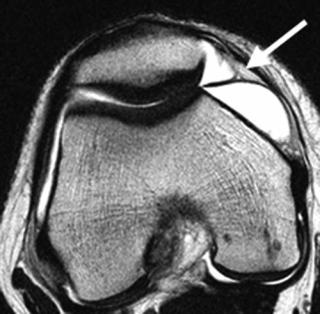 B
B
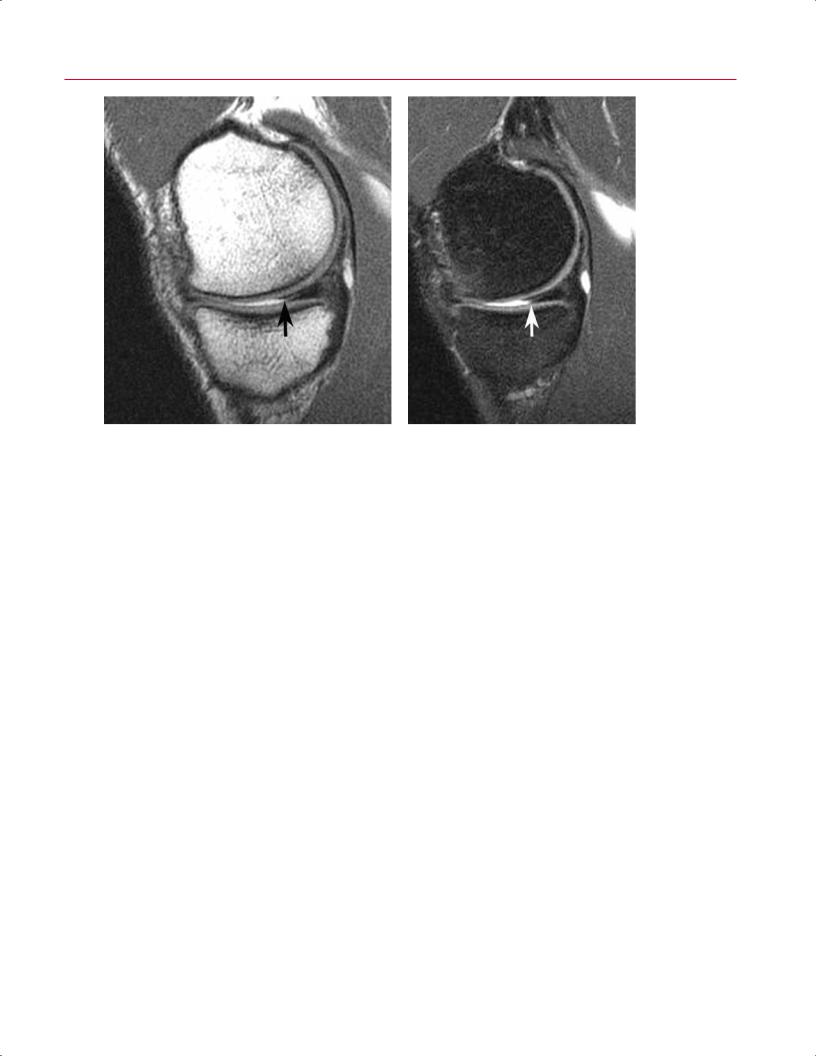
Fig. 8.41 Medial plica. (A) An axial T2-weighted image of the right knee showing a medial plica (arrow) with normal thickness. (B) An axial T2-weighted image of the right knee showing a medial plica (arrow) with thickening in a patient with plica syndrome.
•Suprapatellar
•Infrapatellar
•Lateral
•Medial
Plicae are a common source of atraumatic, activity-associated pain in young, active individuals. The medial plica is the most commonly symptomatic, and it may cause pain secondary to irritation and even abrasion of the medial femoral condyle at approximately 30 degrees of flexion as it rubs across the condyle (Fig. 8.41). The patient typically presents with a sharp, pinching pain, usually on the anteromedial aspect of the knee, associated with activity such as running. Welldeveloped and large plicae can present with a painful popping sensation in the knee. If nonoperative therapy fails to relieve symptoms, arthroscopic release of the o ending plica is indicated. Chondroplasty of the abraded cartilage, if identified, is also indicated.
Bursitis
The pes anserine bursa lies over the tendinous attachment of the sartorius, gracilis, and semitendinosus tendons. The Voshell bursa is deep to the superficial MCL. T2-weighted MR images show fluid in inflamed bursae (Fig. 8.42). Aspiration of the fluid is an option if a collection of fluid is identified. The physical examination is indispensable for this diagnosis because pain on palpation of the pes bursa is the sine qua non of bursitis. Bursae can become infected, which
Fig. 8.42 This coronal fat-suppressed T2-weighted image of the right knee shows fluid accumulation within the bursa (arrow) associated with the insertion of the pes anserine tendons.

8 The Knee 191
A 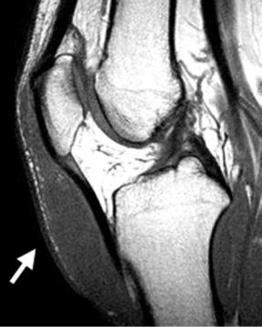
 B
B
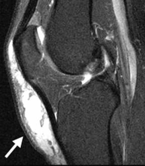
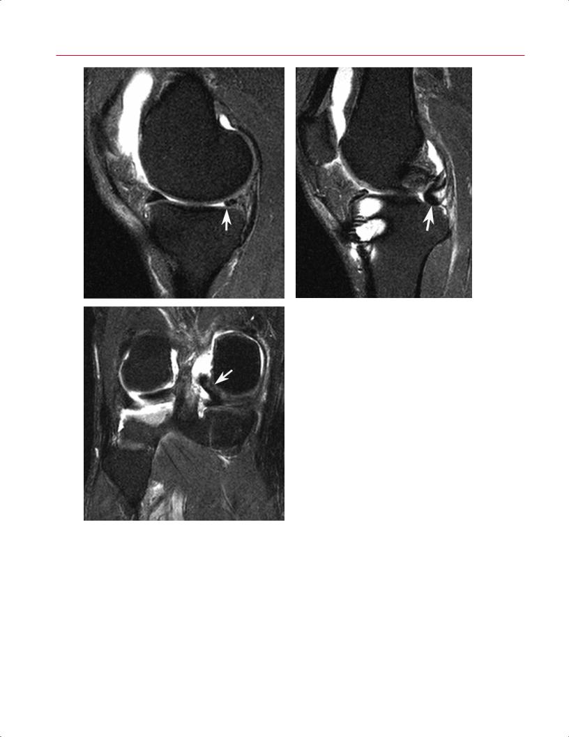
Fig. 8.43 Prepatellar bursitis. Sagittal T1-weighted (A) and fat-suppressed proton-density (B) images show distention of the prepatellar and superficial infrapatellar bursae (arrow on each).
makes treating them more di cult. Saphenous neuritis is in the di erential diagnosis for pain in the proximal, anteromedial knee. If the bursa does not appear to be inflamed on MRI when bursitis is the suspected diagnosis, then a repeat physical examination is warranted and a diagnostic injection should be considered.
Prepatellar bursitis (Fig. 8.43) is a common clinical diagnosis that is seen in active individuals after an abrasion to the anterior aspect of the knee. MRI shows fluid in the prepatellar bursa. Aspiration and, rarely, surgical debridement are used to treat this condition. Similar to prepatellar bursitis, the infrapatellar bursa may also be a ected.
ITB Syndrome
ITB syndrome is a common cause of lateral knee pain in runners. Other conditions in the di erential diagnosis for lateral knee pain include the following:
•LCL injury
•Lateral meniscal tears and degeneration
•Popliteal tendon and hamstring strains
The presence or absence of each of these entities should be evaluated carefully, especially in patients presenting with lateral knee pain. The ITB is best seen on coronal and axial T2weighted and fat-suppressed T2-weighted images. Edema is
seen superficial to the lateral femoral epicondyle, involving the ITB. Small fluid collections, which are relatively poorly defined, and variable thickening of the ITB are often seen. The athlete has pain on palpation over the lateral femoral epicondyle. The classic Ober test is useful for diagnosing a tight ITB. If a tight ITB is found, then stretching is the first line of treatment. Activity modification, nonsteroidal antiinflammatory medications, and modalities such as ultrasound are other options.
Osteonecrosis
Osteonecrosis (also known as avascular necrosis) in the knee is associated with many causative factors (Table 8.656–60); most often, they are atraumatic in nature (Fig. 8.44). The most common atraumatic causes are alcohol abuse and steroid use, but others include the following:
•Gaucher disease
•Sickle cell disease
•Caisson disease
The exact pathophysiology has not been elucidated, but it may involve an increase in intramedullary pressure. Bone death in the femur can involve the epiphysis, metaphysis, and diaphysis. Occurring less commonly than true bone infarcts, osteonecrosis can develop secondary to an insufficiency fracture of the subchondral bone.56 This process,
192 |
III Lower Extremity |
|
|
|
|
|
Table 8.6 Osteonecrosis |
|
|
|
|
|
|
|
|
|
|
|
|
Parameter |
SPONK |
Atraumatic Osteonecrosis of the Knee* |
|
|
Location |
Medial femoral condyle |
Multiple condyles, tibial involvement 20% |
||
|
|
|
|
to 30% |
|
|
Distribution |
Subcortical |
Epiphyseal, metaphyseal, and diaphyseal |
||
|
|
|
|
common |
|
|
Age |
Usually >60 years |
Usually <45 years |
||
|
Bilateral knee involvement |
<1% |
>80% |
|
|
|
Hip involvement |
None |
90% |
|
|
|
Associated risk factors |
Rare |
>80% (e.g., steroids, alcohol) |
||
|
Pathogenesis |
May represent microtrauma, osteoarthritis, or osteopenia |
Multiple theories regarding etiology |
||
|
|
|
|
|
|
*Synonym: secondary or steroid-associated osteonecrosis.
termed SPONK, usually occurs in female patients >60 years old and involves the medial femoral condyle.57 Lesions >2.3 cm2 have been found to lead to osteoarthritis.58
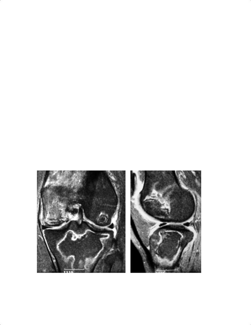
MRI is the most sensitive and specific imaging modality for the early detection of osteonecrosis (Table 8.656–60). Early diagnosis is an important consideration because patients usually do not feel pain until the joint surface collapses, and early detection may make it possible to prevent this collapse. MRI also can help distinguish osteonecrosis and SPONK. On MRI, SPONK appears as a wedge-shaped lesion in the epiphysis that
can extend into the metaphysis and diaphysis. In contrast, atraumatic osteonecrosis shows a serpiginous zone demarcating the extent of the necrosis and bone marrow edema. There can be marrow conversion from red to fatty marrow. The fatty marrow shows high signal intensity on T1-weighted images.61 The lesion in SPONK is subchondral and usually involves collapse and flattening of the medial femoral condyle. It is important to distinguish between these two forms of osteonecrosis because the treatments di er.
A B
Fig. 8.44 Osteonecrosis. Coronal (A) and sagittal (B) fat-suppressed T2-weighted images of the left knee show findings typical for osteonecrosis of the distal femur and proximal tibia. Note the extensive reactive and stress-related bone marrow edema involving the medial
femoral condyle. (From Khanna AJ, Cosgarea AJ, Mont MA, et al. Magnetic resonance imaging of the knee: current techniques and spectrum of disease. J Bone Joint Surg Am 2001;83:128–141. Reprinted by permission.)

|
8 The Knee 193 |
||
Degenerative Joint Disease |
cae and adhesions combine to decrease the volume of the |
|
|
Traditionally, much of the evaluation of degenerative knee |
knee joint and create pseudocompartments. If the steroid |
||
and anesthetic are injected into a pseudocompartment, then |
|||
disease is accomplished with conventional radiographs. In |
|||
the painful areas of the knee are not exposed to the medica- |
|||
the past, when the findings and symptoms of degenerative |
|||
tions, which provides an explanation for why an injection |
|||
knee disease were severe enough, patients were o ered to- |
|||
into the knee may not relieve symptoms. Arthroscopic re- |
|||
tal joint arthroplasty. Currently, for active, physiologically |
|||
lease of adhesions increases the volume of the knee joint and |
|||
young patients with unicompartmental disease, there are |
|||
may restore more normal knee mechanics.62 |
|||
other options, including the following: |
|
|
|
• High tibial osteotomy |
Anterior Interval Scarring |
||
• Unicompartmental arthroplasty |
The anterior interval of the knee is the space between the |
||
• Arthroscopy (for selected patients) |
|||
In the active patient with degenerative knee disease, there |
patellar tendon and the intermeniscal ligament. It usually is |
||
filled with a mobile, compliant fat pad. Surgery and senescent |
|||
are findings on MRI that potentially can be addressed, at |
|||
degeneration of the knee are associated with scarring and |
|||
least temporarily, with less extensive procedures than total |
|||
decreased compliance of this space. Physical examination |
|||
knee arthroplasty; these findings include the following: |
|||
of such patients reveals an immobile, noncompliant patel- |
|||
|
|||
• Scarring of the suprapatellar pouch |
lar tendon. If the patient complains of pain in the anterior |
||
• Complex meniscus tears with flap formation |
aspect of the knee in the presence of fat pad scaring, then |
||
• Localized cartilage lesions |
an excision or release of this scar tissue may be beneficial. |
||
• Scarring and adhesions of the infrapatellar fat pad |
Similar to suprapatellar adhesions, anterior interval scarring |
||
Osteophyte formation is a common finding in degenera- |
appears as linear bands. These bands begin on the patellar |
||
tendon and traverse the fat pad to insert on the anterior as- |
|||
tive disease and contributes to the painful loss of motion of |
|||
pect of the proximal tibia, anterior to the ACL. |
|||
the knee. Typically, flexion contractures occur, which sub- |
|||
|
|
||
stantially hinder a patient’s gait. When flexion contractures |
|
|
|
occur because of a mechanical block to extension, identifica- |
Baker (Popliteal) Cyst |
||
tion of these o ending osteophytes allows for planning for |
A Baker cyst (Fig. 8.45), a classic finding in degenerative |
||
their surgical removal. |
|||
|
knee disease, is a collection of fluid that has escaped from |
||
Degenerative Meniscus |
the joint posteromedially and rests between the medial |
||
Degenerative meniscus refers to a meniscus with complex |
head of gastrocnemius and semimembranosus. Although |
||
the term Baker cyst is commonly used to describe all pop- |
|||
tears and attenuation. Eventually, the meniscus can be ex- |
liteal or synovial cysts in the region of the knee, it should |
||
truded out of the compartment and into the medial or lateral |
be noted that the term is intended for those cases in which |
||
gutter. Initially, primarily one compartment is a ected, de- |
the gastrocnemiosemimembranous bursa is involved.63 The |
||
pending on the alignment of the knee. Because varus align- |
typical MRI findings include a mass in the posterior fossa |
||
ment is more common, the medial compartment, which |
with uniform low signal on T1-weighted images and high |
||
receives most of the forces, usually is a ected primarily. |
signal on T2-weighted images. The walls of the cyst are well |
||
Typically, associated cartilage changes also occur. |
circumscribed. |
||
It is useful to note whether the meniscus appears to have |
These collections can decompress spontaneously into the |
||
degenerated severely and is not functional, or is still essen- |
lower leg. Operative treatment is not usually recommended, |
||
tially intact. This determination helps with patient counsel- |
but when the cyst is present for an extended period of time, |
||
ing and surgical planning. |
the contents may become gelatinous, and then open or ar- |
||
Adhesion Formation |
throscopic intervention may be beneficial. |
||
|
|
||
Part of the degenerative process is the formation of adhesions, especially in the suprapatellar pouch. Adhesions appear as dark gray or black bands on MRI. These bands can be seen in the suprapatellar pouch, usually on sagittal T2weighted images, running from the quadriceps tendon posteriorly to the synovium on the anterior aspect of the femur. The adhesions are thought to a ect the biomechanics of the knee adversely and are a source of ongoing investigation. Pli-
■Infectious Conditions: Osteomyelitis and Septic E usion
Osteomyelitis and septic e usion are common forms of infection involving the knee. MRI is the most sensitive and specific test for the presence of osteomyelitis.64–66 Osteomyelitis causes an intense reaction of the surrounding tissue

194 III Lower Extremity
A B
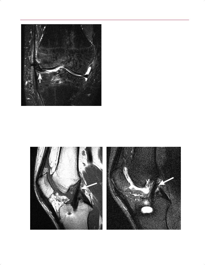
Fig. 8.45 Baker cyst. Sagittal (A) and axial (B) T2-weighted images show distension of the gastrocnemiosemimembranosus bursa (arrow on each).
characterized by edema that is seen on T2-weighted images. A septic e usion can be seen on T2-weighted images as a fluid collection within the joint. Septic arthritis also causes associated bone marrow edema. The diagnosis can be confirmed with aspiration or biopsy, and surgical intervention and antibiotics usually are necessary for treatment. Periarticular osteomyelitis involving the knee joint exhibits a bone marrow edema pattern, hyperintense relative to normal marrow on T2-weighted and STIR images and hypointense on T1-weighted images. Loss of the normally sharply defined low signal intensity cortical margin may occur with osteolysis secondary to infection. An intraosseous fluid collection, surrounded by edema, suggests the presence of focal bone abscess. Septic arthritis may simply exhibit features of a knee joint e usion, but frequently synovial thickening is observed, particularly conspicuous on contrast-enhanced fat-suppressed T1-weighted imaging. Also, a periarticular bone marrow edema pattern may be identified secondary to generalized hyperemia, independent of actual osseous infection.
■ Postoperative Findings
Postoperative Meniscus: Partial
Meniscectomy, Repair, and Allograft
Replacement
Surgical approaches to the treatment of meniscal tears include meniscal debridement or partial meniscec-
tomy, meniscal repair, and meniscal allograft placement. These techniques are designed to stabilize the meniscus while maintaining its shock-absorbing and loading-force- distributing properties. The procedures share the clinical goals of pain relief, restoration of mechanical function, and prevention or mitigation of the development of chondromalacia and osteoarthritis.
With partial meniscectomy, as little meniscal tissue as possible is resected to stabilize the articular margin of the meniscus without excessively exposing the articular cartilage to unprotected impaction forces. Thus, on MRI, it is common to identify the presence of a small tear involving the meniscal remnant (Fig. 8.46). The tear may be stable and asymptomatic. Also, because the process of meniscal debridement creates a new articular surface, intrameniscal MRI findings related to myxoid degeneration may abut the surgically recontoured articular margin, converting internal meniscal signal (noted on T1-weighted or proton-density images) into surface-communicating signal and potentially creating the false impression of a meniscal tear.4 Although T2-weighted imaging and MR arthrography may be used to di erentiate converted intrameniscal signal intensity from a true surface defect into which fluid can dissect, evidence of a surface tear does not necessarily translate to a clinically relevant cause of a patient’s symptoms. However, if, after a conservative partial meniscectomy, a large tear involving the meniscal remnant is noted on MRI, its clinical significance probably is similar to that of a tear in a nondebrided meniscus. After partial meniscectomy, severe tears identified with MRI typically exhibit a complex signal pattern, flap, or
8 The Knee 195
A B
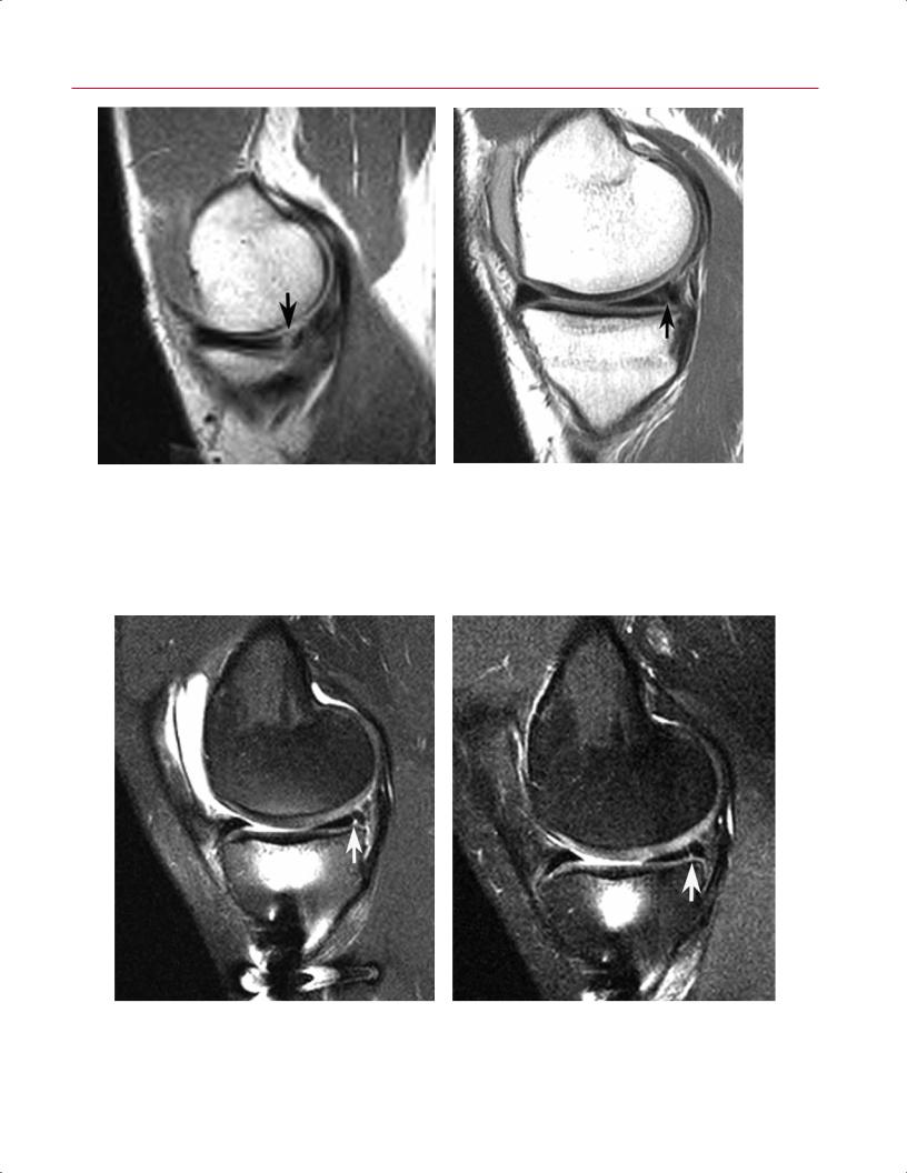
Fig. 8.46 Partial meniscectomy. Sagittal proton-density (A) and sagittal fat-suppressed T2-weighted (B) images show blunting of the anterior margin of the posterior horn of the medial meniscus, con-
fragment displacement or show progressive enlargement on serial postoperative MRI studies67 (Fig. 8.47).
Meniscal repairs, typically performed in the context of a vertical longitudinal tear, often continue to manifest abnormal signal, communicating with the meniscal articular surfaces despite successful stabilization of the meniscus (Fig. 8.48).4,67–69
On serial follow-up MRI examinations, the apparent surface defect may remain, but if progressive development of adjacent chondromalacia or osseous stress reaction is not identified on subsequent postoperative studies and the morphology of the tear remains unchanged, surgical stabilization of the meniscus probably has been achieved (Fig. 8.49). In the case of a displaced meniscal tear that has been repaired, the MRI study should reveal normal meniscal morphology and positioning but, again, the linear tear may remain evident. MR arthrography does not statistically improve accuracy in detecting postoperative meniscal tears and, like nonarthrographic techniques, cannot distinguish between residual and recurrent tears.70 Additionally, the penetration or imbibition
sistent with meniscal debridement. The small horizontal tear (arrow) is unlikely to be clinically symptomatic.
of gadolinium contrast material in a repaired meniscal defect does not necessarily indicate that the tear is unstable or responsible for a patient’s symptoms.
With meniscal allograft procedures, MRI is used to evaluate the positioning of the graft. A graft may be displaced by loading, shearing, or rotational forces that exceed its surgical attachments; by traction related to capsular adhesions or contracture; or by adjacent arthrofibrosis (Fig. 8.50). On MRI, tears involving the meniscal allograft exhibit the same features as do tears in a native meniscus.71
In summary, care must be taken when assessing the clinical significance of MRI findings after meniscal surgery. Most importantly, a meniscal tear involving a debrided or repaired meniscus, even when observed with MR arthrography, does not necessarily correlate with the presence of clinical symptoms or functional impairment. In a patient with knee pain and a history of meniscal surgery, the role of MRI includes evaluation of the knee for other potential symptom-producing pathology, especially chondromalacia, osseous stress injury, and osteonecrosis.72,73
196 III Lower Extremity
A
C
B
Fig. 8.47 Postoperative medial meniscus with displaced flap. (A) A sagittal fat-suppressed proton-density image shows decreased meniscal size (arrow), a finding that may simply reflect partial resection of the meniscus. (B) A sagittal fat-suppressed proton-density image, obtained lateral to the (A) image, shows posterior central displacement of a large meniscal flap, arising from the posterior horn remnant (arrow). (C) A fat-suppressed coronal T2-weighted image of the right knee shows central displacement of a large posterior medial meniscal flap (arrow).
8 The Knee 197
A B
Fig. 8.48 Meniscal repair. (A) A preoperative sagittal T1-weighted image shows a peripheral vertical longitudinal tear (arrow) of the posterior horn of the medial meniscus. (B) A postoperative sagittal
T1-weighted image in the same patient shows persistent signal communication with the articular surface of the meniscus (arrow).
A B
Fig. 8.49 Meniscal repair. (A) A sagittal fat-suppressed proton-density image, obtained after repair of a peripheral vertical longitudinal tear, shows persistent signal communication with the articular surface of
the posterior horn of the medial meniscus (arrow). (B) A sagittal fatsuppressed proton-density image, obtained 1 year later in the same patient, shows stability of the meniscal signal pattern (arrow).
198 III Lower Extremity
ACL Reconstruction
Fig. 8.50 This coronal fat-suppressed T2-weighted image of the right knee shows fibrous adherence of the meniscal allograft (arrow) to the ITB with lateral displacement of the allograft.
The ACL graft is a low signal intensity structure that should run in continuity along approximately the same trajectory as the native ACL (Fig. 8.51). Metallic screws can be identified on MRI by their very dark appearance. Ferromagnetic artifact is a major problem because it can conceal local pathology. Bioabsorbable interference screws and transfixion pins do not cause such artifact. Absorption of bioabsorbable implants varies but takes at least 1 year.74 Cyst formation is a normal finding around these screws as they are absorbed.75 Bone graft incorporation, which can take 3 years or more,75 also can be seen on MRI.
MRI is useful in the evaluation of the patient who has had an ACL reconstruction or repair. The study should be evaluated for the following (Fig. 8.52):
•Presence or absence of graft failure
•Impingement
•Arthrofibrosis
•Placement and orientation of the graft, hardware, and tunnels
Most ACL grafts are 8 to 10 mm wide, and the associated tunnel should not be more than 10 mm wide on MRI. Widening of the graft tunnel can be seen with chronic remodeling secondary to the presence of a ganglion cyst or other process, such as infection, within the graft.
A B
Fig. 8.51 ACL reconstruction. Sagittal T1-weighted (A) and fat-suppressed proton-density (B) images show normal ACL graft trajectory (arrow on each).
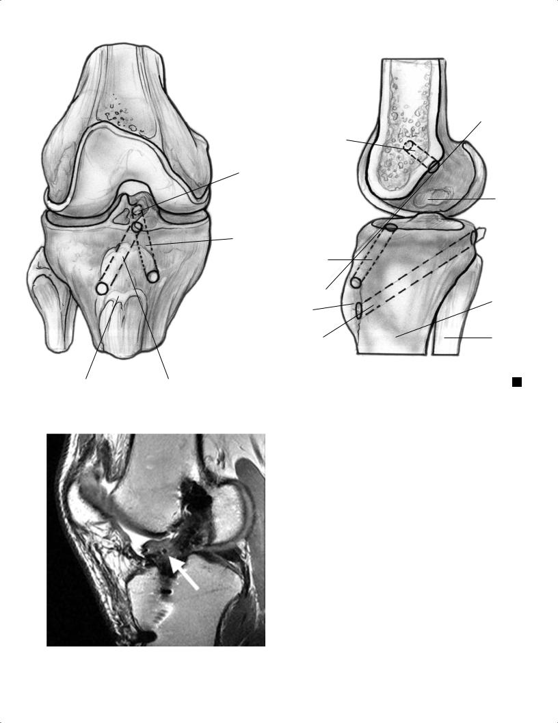
ACL
ACL footplate
ACL tunnel
ACL
Tibial tuberosity
PCL
|
Tibial |
PCL tibial tunnel |
|
A |
|||
tuberosity |
|
F
Intercondylar roof line
PCL bundle sites
Tibia
Femur
B
Fig. 8.52 Artist’s sketches illustrating optimal ACL and PCL graft tunnel placement in the coronal (A) and sagittal (B) planes.
All of the potential sites of osseous impingement should be evaluated carefully, including the following:
• Intercondylar roof
• Intraarticular entrance zones of the bone tunnels
• Side walls of the intercondylar fossa
The MRI findings in roof impingement include posterior bowing of the graft caused by contact of the graft against the roof, increased signal in the distal two thirds of the graft, and placement of the tibial tunnel anterior to the slope of the intercondylar roof when the knee is in an extended position.76
Fig. 8.53 This sagittal proton-density image shows focal arthrofibrosis, consistent with a cyclops lesion (arrow), anterior to an ACL graft.
Cyclops Lesion
The cyclops lesion results from granulation tissue overgrowth of remnant ACL. This entity, which can cause a painful block to full extension, is found anterior to the ACL graft and is easily seen on MRI (Fig. 8.53). Patients with a cyclops lesion often also have associated anterior compartment degenerative changes, which should be evaluated carefully on the MRI study.