

Книги по МРТ КТ на английском языке / MRI for Orthopaedic Surgeons Khanna ed 2010
.pdf160 III Lower Extremity
Inflammatory Disorders
RA is a systemic autoimmune inflammatory disorder that primarily a ects the small joints of the hands and feet but may involve the hip joints late in the disease process. MRI is useful for evaluating erosions, e usion, and synovial pannus formation.68 The synovial proliferation is typically a masslike prominence of tissue within the joint that is hyperintense on fat-suppressed sequences.46 The pannus may be heterogeneous or homogeneous in appearance, and pannus hemorrhages can form with areas of low signal hemosiderin.68 As with osteoarthritis, the MR findings of inflammatory arthritis correlate with the radiographic appearance, including any of the following68:
•Symmetric joint space narrowing
•Periarticular erosions
•Juxtaarticular osteoporosis
•Protrusion acetabulae
Other findings may include the following46:
•Hyperintense joint e usion
•Joint capsule distention
•Hyperintense marrow edema
Fig. 7.14 An oblique axial FSE image of the left hip showing an increased αangle in a nonspherical femoral head with a cam lesion. (© 2009 Hospital for Special Surgery, New York, NY.)
the role of MRI has not been well defined, and conventional radiography is the standard for diagnostic evaluation.69
Ankylosing spondylitis is another form of inflammatory arthritis. It usually involves the spine and larger joints, so the hip is frequently a ected and may be so early in the disease process.46 The hip may be involved in 17 to 35% of patients, but
■ Synovial Disorders
A systematic examination of a hip MRI must include careful scrutiny of the synovium because synovial proliferative
A
Fig. 7.15 Synovial osteochondromatosis. (A) A coronal FSE image of the left hip showing synovial osteochondromatosis with cartilaginous bodies in the inferior capsule (arrows). (B) A coronal fat-suppressed
B
FSE image of the pelvis also showing large detached cartilaginous bodies (arrow). (© 2009 Hospital for Special Surgery, New York, NY.)
7 The Hip 161
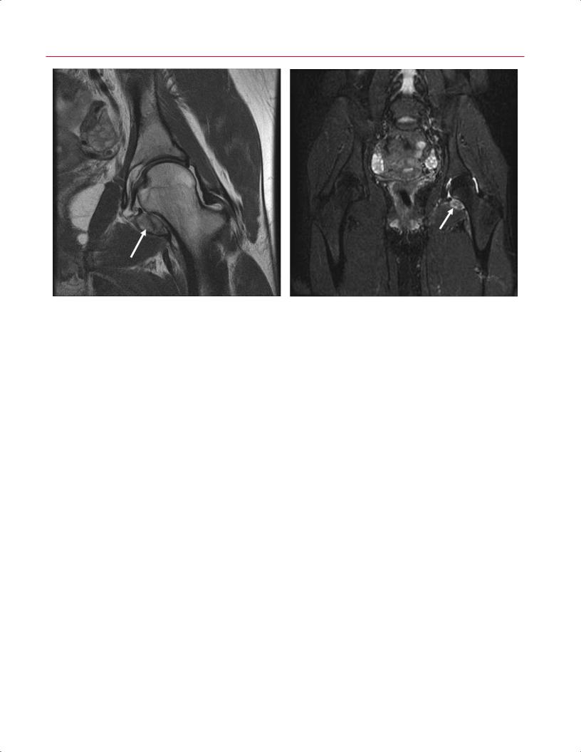
A B
Fig. 7.16 PVNS. (A) A coronal FSE image of the left hip showing PVNS with hemosiderin-laden synovium (arrow). (B) A coronal fat-suppressed FSE image of the pelvis also showing the hemosiderin-laden synovium (arrow). (© 2009 Hospital for Special Surgery, New York, NY.)
disorders are not uncommon. In the hip, negative intraarticular pressure and the tight capsule may result in more prominent erosions than those associated with synovial proliferative disorders in other joints such as the knee, which has several patulous synovial recesses.46 Asymmetric fluid is seen on body coil fat-suppressed images, and fine synovial debris is present on the surface coil images in the setting of synovial osteochondromatosis, which is a monoarticular synovium-based cartilage metaplasia that commonly involves the hip joint (Fig. 7.15).46,70 The development of intraarticular loose bodies may converge to create large pressure erosions of the femoral neck and head or result in destruction of the hyaline cartilage. Typical MRI characteris-
References
1.Schmid MR, Nötzli HP, Zanetti M, Wyss TF, Hodler J. Cartilage lesions in the hip: diagnostic e ectiveness of MR arthrography. Radiology 2003;226:382–386
2.Kassarjian A, Yoon LS, Belzile E, Connolly SA, Millis MB, Palmer WE. Triad of MR arthrographic findings in patients with cam-type femoroacetabular impingement. Radiology 2005;236:588–592
3.Kramer J, Recht MP. MR arthrography of the lower extremity. Radiol Clin North Am 2002;40:1121–1132
4.Potter HG, Foo LF. Magnetic resonance imaging of articular cartilage: trauma, degeneration, and repair. Am J Sports Med 2006;34:661– 677
5.Mintz DN, Hooper T, Connell D, Buly R, Padgett DE, Potter HG. Magnetic resonance imaging of the hip: detection of labral and chondral abnormalities using noncontrast imaging. Arthroscopy 2005;21:385–393
tics include multiple ossified loose bodies (low to intermediate signal intensity) surrounded by a high signal intensity joint e usion.46
PVNS may create a similar appearance, but the presence of hemosiderin degradation products creates a low signal intensity that can be quite helpful in confirming the diagnosis (Fig. 7.16).71 PVNS has two forms: nodular and di use.71 In its nodular form, it is seen as a focus of solitary, bulky synovial debris within the anteromedial recess or bare area.46 If left untreated, synovial proliferative disorders may lead to a rapid degradation of articular cartilage with resultant osteoarthritis in a short period of time. (For a complete discussion of synovial proliferative disorders, see Chapter 15.)
6.Toomayan GA, Holman WR, Major NM, Kozlowicz SM, Vail TP. Sensitivity of MR arthrography in the evaluation of acetabular labral tears. AJR Am J Roentgenol 2006;186:449–453
7.Kelly BT, Williams RJ III, Philippon MJ. Hip arthroscopy: current indications, treatment options, and management issues. Am J Sports Med 2003;31:1020–1037
8.McCarthy JC, Noble PC, Schuck MR, Wright J, Lee J. The Otto E. Aufranc Award: the role of labral lesions to development of early degenerative hip disease. Clin Orthop Relat Res 2001;393:25–37
9.Dinauer PA, Murphy KP, Carroll JF. Sublabral sulcus at the posteroinferior acetabulum: a potential pitfall in MR arthrography diagnosis of acetabular labral tears. AJR Am J Roentgenol 2004;183:1745–1753
10.Kelly BT, Shapiro GS, Digiovanni CW, Buly RL, Potter HG, Hannafin JA. Vascularity of the hip labrum: a cadaveric investigation. Arthroscopy 2005;21:3–11

162 III Lower Extremity
11.Kim YT, Azuma H. The nerve endings of the acetabular labrum. Clin Orthop Relat Res 1995;320:176–181
12.Lecouvet FE, Vande Berg BC, Malghem J, et al. MR imaging of the acetabular labrum: variations in 200 asymptomatic hips. AJR Am J Roentgenol 1996;167:1025–1028
13.Kelly BT, Weiland DE, Schenker ML, Philippon MJ. Arthroscopic labral repair in the hip: surgical technique and review of the literature. Arthroscopy 2005;21:1496–1504
14.Seldes RM, Tan V, Hunt J, Katz M, Winiarsky R, Fitzgerald RH Jr. Anatomy, histologic features, and vascularity of the adult acetabular labrum. Clin Orthop Relat Res 2001;382:232–240
15.Lage LA, Patel JV, Villar RN. The acetabular labral tear: an arthroscopic classification. Arthroscopy 1996;12:269–272
16.Ilizaliturri VM Jr, Byrd JWT, Sampson TG, et al. A geographic zone method to describe intra-articular pathology in hip arthroscopy: cadaveric study and preliminary report. Arthroscopy 2008;24:534– 539
17.Byrd JWT. Labral lesions: an elusive source of hip pain case reports and literature review. Arthroscopy 1996;12:603–612
18.Armstrong DW III, Rue JPH, Wilckens JH, Frassica FJ. Stress fracture injury in young military men and women. Bone 2004;35:806–816
19.Anderson K, Strickland SM, Warren R. Hip and groin injuries in athletes. Am J Sports Med 2001;29:521–533
20.Boden BP, Osbahr DC. High-risk stress fractures: evaluation and treatment. J Am Acad Orthop Surg 2000;8:344–353
21.Fredericson M. Diagnosing tibial stress injuries in athletes. West J Med 1995;162:150
22.Potter HG, Montgomery KD, Heise CW, Helfet DL. MR imaging of acetabular fractures: value in detecting femoral head injury, intraarticular fragments, and sciatic nerve injury. AJR Am J Roentgenol 1994;163: 881–886
23.Laorr A, Greenspan A, Anderson MW, Moehring HD, McKinley T. Traumatic hip dislocation: early MRI findings. Skeletal Radiol 1995;24:239–245
24.Moorman CT III, Warren RF, Hershman EB, et al. Traumatic posterior hip subluxation in American football. J Bone Joint Surg Am 2003;85:1190–1196
25.Shindle MK, Ranawat AS, Kelly BT. Diagnosis and management of traumatic and atraumatic hip instability in the athletic patient. Clin Sports Med 2006;25:309–326
26.Byrd JWT. Lateral impact injury. A source of occult hip pathology. Clin Sports Med 2001;20:801–815
27.Dwek J, Pfirrmann C, Stanley A, Pathria M, Chung CB. MR imaging of the hip abductors: normal anatomy and commonly encountered pathology at the greater trochanter. Magn Reson Imaging Clin N Am 2005;13:691–704
28.Kingzett-Taylor A, Tirman PF, Feller J, et al. Tendinosis and tears of gluteus medius and minimus muscles as a cause of hip pain: MR imaging findings. AJR Am J Roentgenol 1999;173:1123–1126
29.Chung CB, Robertson JE, Cho GJ, Vaughan LM, Copp SN, Resnick D. Gluteus medius tendon tears and avulsive injuries in elderly women: imaging findings in six patients. AJR Am J Roentgenol 1999;173:351–353
30.Bunker TD, Esler CNA, Leach WJ. Rotator-cu tear of the hip. J Bone Joint Surg Br 1997;79:618–620
31.Howell GED, Biggs RE, Bourne RB. Prevalence of abductor mechanism tears of the hips in patients with osteoarthritis. J Arthroplasty 2001;16:121–123
32.LaBan MM, Weir SK, Taylor RS. “Bald trochanter” spontaneous rupture of the conjoined tendons of the gluteus medius and mini-
mus presenting as a trochanteric bursitis. Am J Phys Med Rehabil 2004;83:806–809
33.Jacobson T, Allen WC. Surgical correction of the snapping iliopsoas tendon. Am J Sports Med 1990;18:470–474
34.Papadopoulos EC, Korres DS, Papachristou G, Efstathopoulos N. Piriformis syndrome. Orthopedics 2004;27:797, 799, author reply 799
35.Meislin R, Abeles A. Role of hip MR imaging in the management of sports-related injuries. Magn Reson Imaging Clin N Am 2005;13:635– 640
36.Palmer WE, Kuong SJ, Elmadbouh HM. MR imaging of myotendinous strain. AJR Am J Roentgenol 1999;173:703–709
37.Pavlov H. Roentgen examination of groin and hip pain in the athlete. Clin Sports Med 1987;6:829–843
38.Bencardino JT, Kassarjian A, Palmer WE. Magnetic resonance imaging of the hip: sports-related injuries. Top Magn Reson Imaging 2003;14:145–160
39.Lavernia CJ, Sierra RJ, Grieco FR. Osteonecrosis of the femoral head. J Am Acad Orthop Surg 1999;7:250–261
40.Coleman BG, Kressel HY, Dalinka MK, Scheibler ML, Burk DL, Cohen EK. Radiographically negative avascular necrosis: detection with MR imaging. Radiology 1988;168:525–528
41.Hauzeur JP, Pasteels JL, Schoutens A, et al. The diagnostic value of magnetic resonance imaging in non-traumatic osteonecrosis of the femoral head. J Bone Joint Surg Am 1989;71:641–649
42.Mitchell DG, Steinberg ME, Dalinka MK, Rao VM, Fallon M, Kressel HY. Magnetic resonance imaging of the ischemic hip. Alterations within the osteonecrotic, viable, and reactive zones. Clin Orthop Relat Res 1989;244:60–77
43.Totty WG, Murphy WA, Ganz WI, Kumar B, Daum WJ, Siegel BA. Magnetic resonance imaging of the normal and ischemic femoral head. AJR Am J Roentgenol 1984;143:1273–1280
44.Hayes CW, Balkissoon AA. Magnetic resonance imaging of the musculoskeletal system. II. The hip. Clin Orthop Relat Res 1996;322:297– 309
45.Shimizu K, Moriya H, Akita T, Sakamoto M, Suguro T. Prediction of collapse with magnetic resonance imaging of avascular necrosis of the femoral head. J Bone Joint Surg Am 1994;76:215–223
46.Stoller DW, Sampson T, Bredella M. The hip. In: Stoller DW, ed. Magnetic Resonance Imaging in Orthopaedics and Sports Medicine. Philadelphia: Lippincott Williams & Wilkins; 2007:41–304.
47.Takatori Y, Kamogawa M, Kokubo T, et al. Magnetic resonance imaging and histopathology in femoral head necrosis. Acta Orthop Scand 1987;58:499–503
48.Khanna AJ, Yoon TR, Mont MA, Hungerford DS, Bluemke DA. Femoral head osteonecrosis: detection and grading by using a rapid MR imaging protocol. Radiology 2000;217:188–192
49.La orgue P, Dahan E, Chagnaud C, Schiano A, Kasbarian M, Acquaviva PC. Early-stage avascular necrosis of the femoral head: MR imaging for prognosis in 31 cases with at least 2 years of follow-up. Radiology 1993;187:199–204
50.Koo KH, Kim R. Quantifying the extent of osteonecrosis of the femoral head. A new method using MRI. J Bone Joint Surg Br 1995;77:875– 880
51.Cherian SF, Laorr A, Saleh KJ, Kuskowski MA, Bailey RF, Cheng EY. Quantifying the extent of femoral head involvement in osteonecrosis. J Bone Joint Surg Am 2003;85:309–315
52.Beltran J, Herman LJ, Burk JM, et al. Femoral head avascular necrosis: MR imaging with clinical-pathologic and radionuclide correlation. Radiology 1988;166(1 Pt 1):215–220

7 The Hip 163
53.Kalliakmanis AG, Pneumaticos S, Plessas S, Papachristou G. Transient hip osteoporosis. Orthopedics 2006;29:263–264
54.Beltran J, Opsha O. MR imaging of the hip: osseous lesions. Magn Reson Imaging Clin N Am 2005;13:665–676
55.Siebenrock KA, Wahab KHA, Werlen S, Kalhor M, Leunig M, Ganz R. Abnormal extension of the femoral head epiphysis as a cause of cam impingement. Clin Orthop Relat Res 2004;418:54–60
56.Siebenrock KA, Schoeniger R, Ganz R. Anterior femoro-acetabular impingement due to acetabular retroversion. Treatment with periacetabular osteotomy. J Bone Joint Surg Am 2003;85:278–286
57.Beck M, Leunig M, Parvizi J, Boutier V, Wyss D, Ganz R. Anterior femoroacetabular impingement: part II. Midterm results of surgical treatment. Clin Orthop Relat Res 2004;418:67–73
58.Ganz R, Parvizi J, Beck M, Leunig M, Nötzli H, Siebenrock KA. Femoroacetabular impingement: a cause for osteoarthritis of the hip. Clin Orthop Relat Res 2003;417:111–119
59.Lavigne M, Parvizi J, Beck M, Siebenrock KA, Ganz R, Leunig M. Anterior femoroacetabular impingement: part I. Techniques of joint preserving surgery. Clin Orthop Relat Res 2004;418:61–66
60.Ito K, Minka MA II, Leunig M, Werlen S, Ganz R. Femoroacetabular impingement and the cam-e ect. A MRI-based quantitative anatomical study of the femoral head-neck o set. J Bone Joint Surg Br 2001;83:171–176
61.Tanzer M, Noiseux N. Osseous abnormalities and early osteoarthritis: the role of hip impingement. Clin Orthop Relat Res 2004;429:170–177
62.Beck M, Kalhor M, Leunig M, Ganz R. Hip morphology influences the pattern of damage to the acetabular cartilage: femoroacetabular im-
pingement as a cause of early osteoarthritis of the hip. J Bone Joint Surg Br 2005;87:1012–1018
63.Nötzli HP, Wyss TF, Stoecklin CH, Schmid MR, Treiber K, Hodler J. The contour of the femoral head-neck junction as a predictor for the risk of anterior impingement. J Bone Joint Surg Br 2002;84:556–560
64.Reynolds D, Lucas J, Klaue K. Retroversion of the acetabulum. A cause of hip pain. J Bone Joint Surg Br 1999;81:281–288
65.Bredella MA, Stoller DW. MR imaging of femoroacetabular impingement. Magn Reson Imaging Clin N Am 2005;13:653–664
66.Shindle MK, Voos JE, Heyworth BE, et al. Hip arthroscopy in the athletic patient: current techniques and spectrum of disease. J Bone Joint Surg Am 2007;89(suppl 3):29–43
67.Sadro C. Current concepts in magnetic resonance imaging of the adult hip and pelvis. Semin Roentgenol 2000;35:231–248
68.Koulouris G, Morrison WB. MR imaging of hip infection and inflammation. Magn Reson Imaging Clin N Am 2005;13:743–755
69.Wilkinson M, Bywaters EGL. Clinical features and course of ankylosing spondylitis; as seen in a follow-up of 222 hospital referred cases. Ann Rheum Dis 1958;17:209–228
70.Szypryt P, Twining P, Preston BJ, Howell CJ. Synovial chondromatosis of the hip joint presenting as a pathological fracture. Br J Radiol 1986;59:399–401
71.Tyler WK, Vidal AF, Williams RJ, Healey JH. Pigmented villonodular synovitis. J Am Acad Orthop Surg 2006;14:376–385

8 The Knee
Brett M. Cascio, A. Jay Khanna, Sergio A. Glait, Andrew J. Cosgarea, Timothy S. Johnson, and John D. Reeder
■Specialized Pulse Sequences and Protocols
For MRI of the knee, the patient is positioned with the leg in comfortable external rotation. Sagittal, coronal, and axial imaging is obtained with fat-suppressed acquisition in at least one plane. To optimize spatial resolution, thinner segments are preferred, but the choice of segment thickness must be balanced with signal-to-noise and scan time constraints. In general, MRI systems with higher field strengths can achieve thinner segments with a better signal-to-noise ratio in less time than can units with lower field strength. For most SE protocols designed for knee imaging, the e ective segment thickness is 3 to 4 mm; that for gradient-echo imaging is 1 to 3 mm.
A typical low magnetic field strength protocol for knee imaging may include T1-weighted and T2-weighted sagittal acquisitions, a coronal STIR sequence, and an axial FSE T2weighted sequence. A sagittal 3D gradient-echo sequence represents an additional option, particularly with low field strength systems; this high-resolution technique o ers a relatively thin segment with a superior signal-to-noise ratio, useful for meniscal assessment. A high field strength approach to knee imaging may include the following sequences:
•Sagittal FSE proton-density fat-suppressed sequence to evaluate the following:
οMenisci
οArticular cartilage
οCruciate ligaments
οExtensor mechanism
οArticular fluid
•Coronal FSE fat-suppressed T2-weighted sequence to assess the following:
οOsseous injury
οArticular and meniscal cartilage
οCollateral supporting structures
οFluid distribution
•Sagittal T1-weighted sequence to evaluate the following:
οEvaluate marrow and subcutaneous fat
οDetect heterotopic ossification
οProvide further evaluation of meniscal integrity
•Axial FSE T2-weighted sequence primarily to assess the patellofemoral joint
■Traumatic Pathology
Acute Hemarthrosis
Acute knee trauma commonly presents with pain and hemarthrosis. ACL tears are seen in more than 70% of acute hemarthroses.1 Usually, ACL tears are associated with other injuries such as meniscal tears, osteochondral fractures, patellar dislocations, and ligament and tendon tears. MRI is commonly used to discern the etiology of an acute hemarthrosis, especially when the knee is too tender or the patient is too anxious for a thorough physical examination. MRI is especially helpful when conventional radiographs are negative. Typically, acute hemarthrosis appears as fluid within the joint with high signal intensity on T2-weighted images and intermediate signal intensity on T1-weighted images. Similar findings can be seen with inflammatory processes, resulting in a nontraumatic knee e usion, and the two processes may be di erentiated by the clinician, based on the history and physical examination. The presence of blood in joint fluid causes a relatively brighter appearance on T1 imaging than that observed with nonhemorrhagic fluid because of the e ect of methemoglobin. Hemosiderin deposition within joint fluid, associated with chronic hemorrhage or PVNS, appears dark on all pulse sequences.
Table 8.1 Grading of Meniscal Tears
Grade Pathologic and MRI Findings
1Degenerative process; focal, globular intrasubstance increased signal; no extension to articular surface
2Degenerative process; horizontal, linear intrasubstance increased signal; no extension to articular surface
3Meniscal tear; increased signal extends to or communicates with at least one articular surface
4Complex tear/macerated meniscus
Source: From Khanna AJ, Cosgarea AJ, Mont MA, et al. Magnetic resonance imaging of the knee: current techniques and spectrum of disease. J Bone Joint Surg Am 2001;83:128–141. Reprinted by permission.
164
|
8 The Knee 165 |
||
|
|
|
|
Meniscal Tears |
trasubstance degeneration that can be seen only on MRI to |
||
Meniscal tears are a very common finding on MRI. Clinical |
complete tears that allow fragments of the meniscus to flip |
||
or displace. |
|||
suspicion of a meniscal tear is a common reason for order- |
|||
Meniscal tears are graded according to how they appear on |
|||
ing an MRI. Tears can be a source of pain and disability, or |
|||
MRI (Table 8.12; Fig. 8.1), and are best seen on T1-weighted, |
|||
they can be incidental findings. The tears can range from in- |
gradient-echo, and proton-density images. The menisci are |
||
|
|||
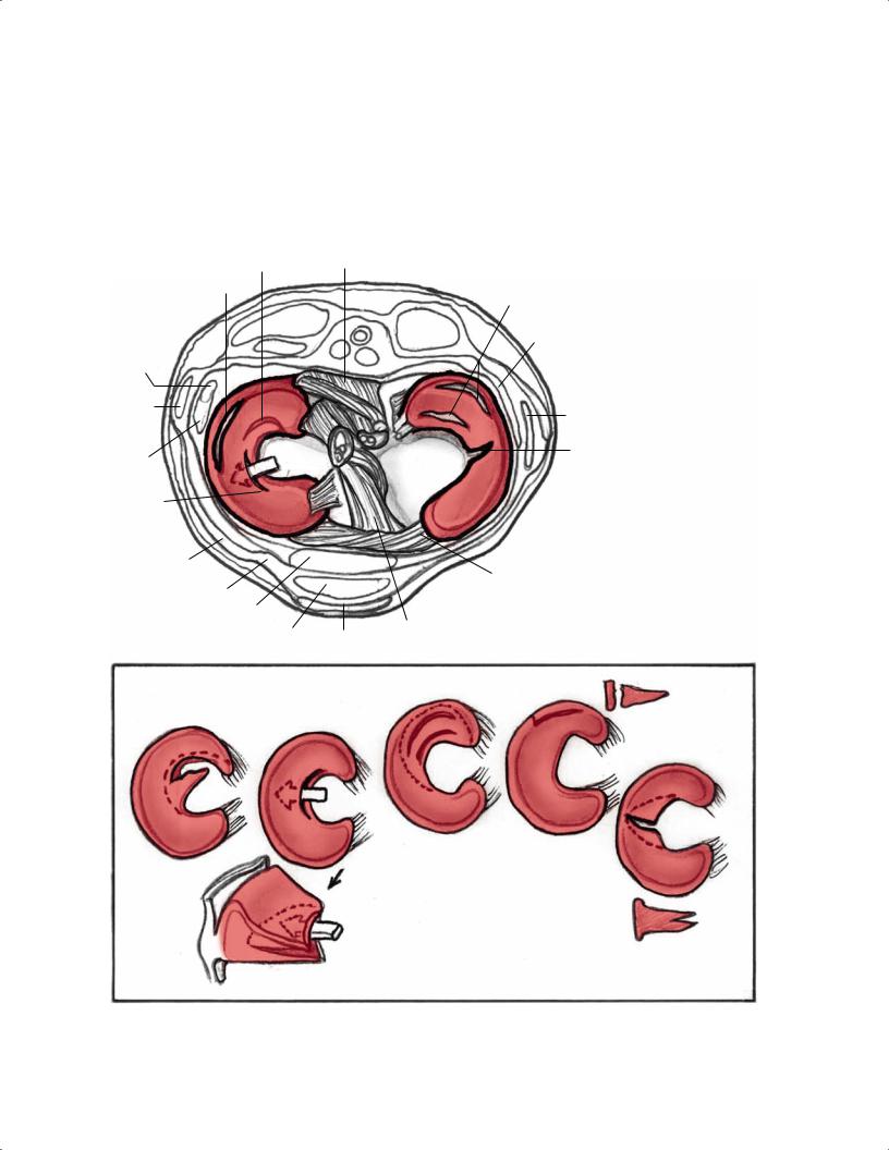
Degenerative flap tear (A)
Peripheral tear (D)
Peroneal nerve
Biceps tendon
LCL
Horizontal cleavage tear (B)
Iliotibial tract
Patellar retinaculum
Fat
Patellar tendon
A
B
PCL
Medial
Complex tear (C)
Joint capsule
MCL
Radial tear (E)
Transverse ligament
ACL
Bursa
C D
E
B
Fig. 8.1 Artist’s sketch illustrating the morphology of meniscal tear patterns and relevant anatomy of the knee: (A) degenerative flap tear,
(B) horizontal cleavage tear, (C) complex tear, (D) peripheral vertical longitudinal tear, and (E) vertical radial tear.
166 |
III Lower Extremity |
|
|
|
|
|
Table 8.2 Characteristics of Meniscal Tears on MRI |
|
|
||
|
|
|
|
|
|
|
|
Meniscal Tear Morphology |
Description |
Appearance on MRI |
|
|
|
Horizontal |
Separates meniscus into superior (femoral) and inferior |
Primarily horizontal signal on sagittal images |
|
|
|
|
(tibial) fragments |
|
|
|
|
Vertical radial |
Splits central margin of meniscus |
Vertical signal oriented perpendicular to the |
|
|
|
|
|
curvature of the meniscus |
|
Vertical longitudinal |
Extends along length of meniscus; separates meniscus |
|
into inner and outer fragments |
Bucket handle |
Subtype of the longitudinal tear in which the displaced |
|
central fragment resembles a bucket handle |
Complex |
Combination of multiple planes; commonly horizontal |
|
and radial |
Meniscocapsular separation |
Rupture of meniscus-capsule junction |
Vertical signal oriented parallel to the curvature of the meniscus.
“Double-PCL” sign; displaced fragment often seen parallel to the PCL in the intercondylar notch on sagittal images
Characteristics of each tear type or fragmented/ macerated
Increased signal between the edge of the meniscus and the capsule
Source: Adapted from Khanna AJ, Cosgarea AJ, Mont MA, et al. Magnetic resonance imaging of the knee: current techniques and spectrum of disease. J Bone Joint Surg Am 2001;83:128–141, combined with information from Kelley EA, Berquist TH. Knee. In: Berquist TH, ed. MRI of the Musculoskeletal System. Philadelphia: Lippincott Williams & Wilkins; 2006:303–429. Adapted by permission.
low intensity on all sequences.3–10 Most tears involve the medial meniscus, but most acute tears involve the lateral meniscus (Table 8.22,11). Special attention should be given to the menisci in the presence of a chronic ACL tear because associated meniscus tears are common. The medial meniscus is commonly torn in the chronically ACL-deficient knee because the meniscus plays a secondary stabilizing role to anterior tibial translation.
The types of meniscal tear morphologies have been well described (Table 8.22,11). In early publications on MRI evaluation of meniscal pathology, detection focused primarily on meniscal signal intensity patterns and their relationship to the meniscal surface.12,13 Grade I and grade II9 meniscal tears referred to increased intrameniscal signal that appeared punctate or linear, respectively, and were particularly evident on T1-weighted images. The grade III designation indicated
A
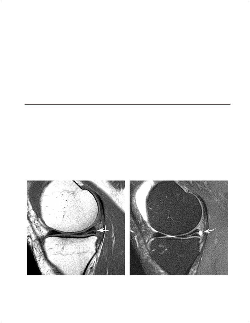
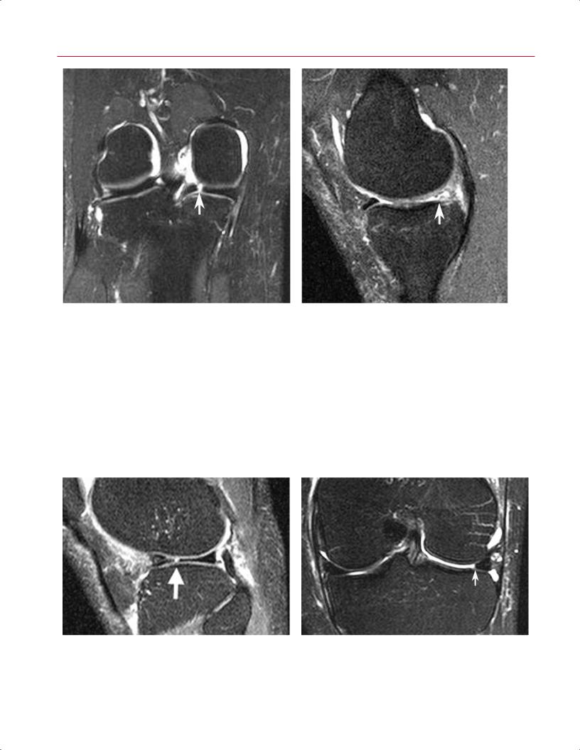
Fig. 8.2 Horizontal tear in the posterior horn of the medial meniscus. Sagittal T1-weighted (A) and fat-suppressed proton-density
(B) images showing a horizontal tear (arrow on each) communicat-
B
ing with the undersurface of the meniscus. Note the small meniscal cyst posterior to the meniscus on the fat-suppressed proton-density image.
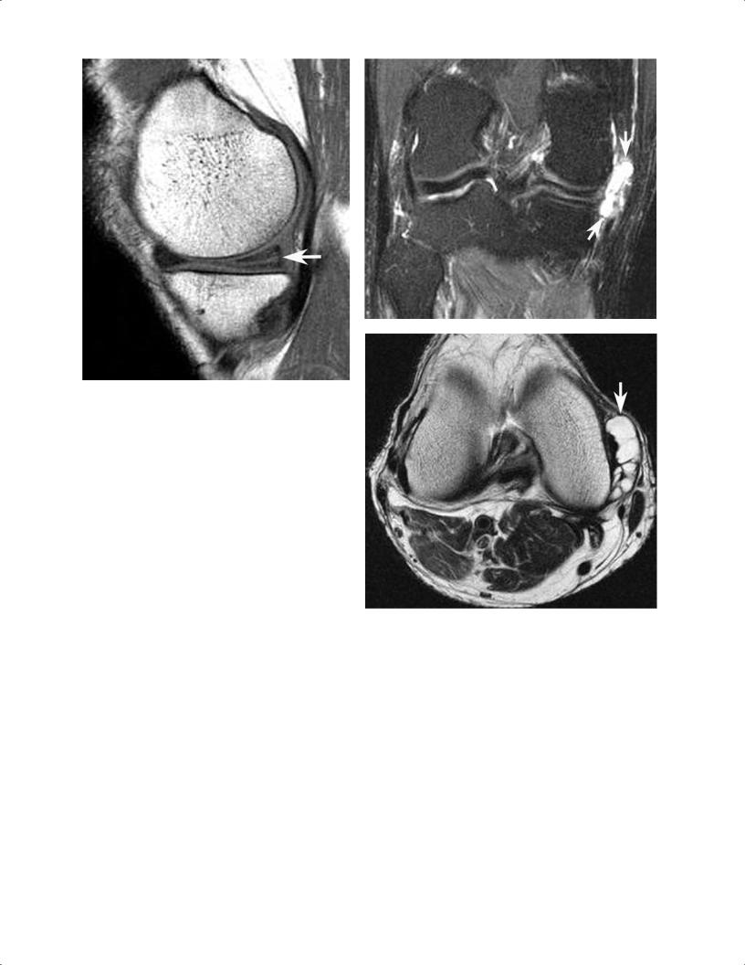
A
Fig. 8.3 Horizontal medial meniscal tear with large meniscal cyst in the right knee. (A) A sagittal T1-weighted image shows a horizontal tear (arrow) of the posterior horn of the medial meniscus. (B) A coronal fat-suppressed T2-weighted image shows a large meniscal cyst (arrows) extending medial to the medial compartment. (C) An axial T2-weighted image shows a multiloculated meniscal cyst (arrow).
that the signal intensity pattern communicated with the superior or inferior meniscal surface, and therefore most likely corresponded to an arthroscopically identifiable meniscal tear.9 If grade II meniscal pathology was reported in an MRI interpretation as a grade II tear, however, it could create the erroneous impression that meniscal surface pathology existed. Although grade II intrameniscal signal can reflect the presence of a meniscal contusion or an intrameniscal tear, it may also denote myxoid internal meniscal degeneration, artifact (magic angle e ect or truncation), or normal meniscal vascularity in a child or young adult.14,15 This grading system also does not consider morphologic alterations in characterizing meniscal pathology. Because the morphology of a meniscal tear impacts its relative clinical significance and influences surgical planning, a more specific classification
B
C
system, currently a orded wide acceptance, uses MRI findings to categorize tears as follows13:
•Horizontal
•Vertical radial
•Vertical longitudinal with/without flap displacement
•Complex
Horizontal tears divide the meniscus into superior and inferior components, identified on sagittal and coronal imaging series (Fig. 8.2). The tear often communicates with the inferior meniscal surface; sometimes a concomitant meniscal cyst is identified, involving the perimeniscal soft tissue (Fig. 8.3).
168 III Lower Extremity
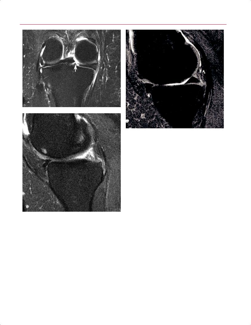
A B
Fig. 8.4 Vertical radial meniscal tear in the posterior horn of the medial meniscus in the right knee. (A) A coronal fat-suppressed T2weighted image shows a vertical defect (arrow) involving the posterior horn of the medial meniscus. (B) A sagittal fat-suppressed
Vertical radial tears exhibit a linear signal pattern. They violate the superior and inferior meniscal surfaces and are oriented perpendicular to the meniscal axis of curvature.16 As such, if a vertical radial tear involves the anterior or posterior portion of the meniscus, the tear will show a linear vertical configuration on coronal images (Fig. 8.4A) and an abrupt truncation of the central meniscal contour on sagittal images (Fig. 8.4B). With this type of tear, the change
proton-density image, obtained in the plane of the tear, shows truncation (arrow) and abnormal signal intensity involving the posterior horn. Note the normal anterior horn.
in meniscal morphology, appreciated in the imaging plane oriented parallel to the tear, is equally as important as the surface communication of linear abnormal meniscal signal intensity, noted in the imaging plane perpendicular to the axis of the tear. If the vertical radial tear involves the midbody of the meniscus, a linear meniscal defect is noted on sagittal images (Fig. 8.5A), and blunting or truncation of the central meniscal contour is observed on coronal images (Fig.
A B
Fig. 8.5 Vertical radial meniscal tear in the mid-body lateral meniscus in the left knee. (A) A sagittal fat-suppressed proton-density image shows a vertical tear (arrow) of the central edge of the lateral meniscus, oriented perpendicular to the curvature of the meniscus.
Note the superimposed horizontal tear of the anterior horn. (B) A coronal fat-suppressed T2-weighted image shows the same tear with truncation of the central meniscal margin (arrow).
8 The Knee 169
A
B
|
Fig. 8.6 Vertical radial tear of the meniscal root in the right knee. (A) |
|
A coronal fat-suppressed T2-weighted image shows a vertical radial |
|
defect (arrow) at the meniscal root. (B) A sagittal fat-suppressed pro- |
|
ton-density image, obtained just medial to the tear, shows normal |
|
posterior horn morphology. (C) A sagittal fat-suppressed proton-den- |
|
sity image, obtained in the plane of the tear, shows abrupt transition |
C |
to markedly abnormal posterior meniscal morphology, correspond- |
ing to the meniscal root tear. |
8.5B). A commonly overlooked vertical radial tear occurs at |
cal linear signal intensity interfacing with the superior and |
the root of the posterior horn of the medial meniscus (Fig. |
inferior meniscal articular surfaces on sagittal and coronal |
8.6). This tear, particularly common in obese patients, de- |
imaging planes. Peripheral vertical longitudinal tears of the |
stabilizes the meniscus, and medial extrusion of the menis- |
posterior horn of the medial meniscus and vertical longitu- |
cus is often identified on MRI. Chondromalacia and osseous |
dinal tears of the posterior horn of the lateral meniscus at |
stress injury are also frequently observed in association with |
the attachment of the meniscofemoral ligament are com- |
these radial tears of the root of the posterior horn of the me- |
monly associated with ACL tears (Fig. 8.7). Displacement of |
dial meniscus.17 |
a meniscal flap associated with a vertical longitudinal tear |
Vertical longitudinal tears also exhibit a vertical signal |
may occur, and unstable meniscal tears are more likely to |
orientation on MRI, but because the tear is oriented parallel |
be symptomatic and impair biomechanics; in such circum- |
to the axis of meniscal curvature, it is identified as a verti- |
stances, surgical intervention usually is necessary to restore |