

NUCLEAR POWER PLANTS
.pdfCross-Flow-Induced-Vibrations in Heat Exchanger Tube Bundles: A Review |
75 |
analysis. However, this requires an understanding of vibration excitation and damping mechanism in two-phase flow. A number of flow regimes (Table 1) can occur for a given boundary configuration, depending upon the concentration and size of the gas bubbles and on the mass flow rates of the two-phases. Two-phase (khushnood, et al., 2004) flow characteristics greatly depend upon the type of flow occurring.
Flow |
Average Void |
Specification |
|
Type |
Fraction |
||
|
|||
Bubble |
~0.3 |
Some bubbles are present in liquid flow and move with the |
|
same velocity. |
|||
|
|
||
Slug |
0.3-0.5 |
Liquid slugs flow intermittently. |
|
Froth |
0.5-0.8 |
More violent intermittent flow. |
|
|
|
|
|
Annular |
0.8-0.9 |
Mainly gas flow. Liquid adheres to the tube surface. |
|
|
|
|
|
Mist |
~0.9 |
Almost gas flow. Mist sometimes causes energy dissipation. |
Table 1. Types of Flow in Two-Phases (khushnood, et al., 2004)
Vibration of tube in two-phase flow displays different flow regimes i.e., gas and liquid phase distributions, depending upon the void fraction and mass flux. It is known that four mechanisms are responsible for the excitation of tube arrays in cross-flow (Pettigrew, et al., 1991). These mechanisms are: turbulence buffeting, vortex shedding or Strouhal periodicity, fluid-elastic instability and acoustic resonance. Table 2 presents a summary of these vibration mechanisms for single cylinder and tube bundles for liquid, gas and liquid-gas two-phase flow respectively. Of these four mechanisms, fluid-elastic instability is the most damaging in the short term, because it causes the tubes to vibrate excessively, leading to rapid wear at the tube supports. This mechanism occurs once the flow rate exceeds a threshold velocity at which tubes become self-excited and the vibration amplitude rises rapidly with an increase in flow velocity.
Flow Situation |
Fluid-Elastic |
Periodic |
|
Turbulence |
|
Acoustic |
|
|||
(Cross-Flow) |
Instability |
Shedding |
|
Excitation |
|
Resonance |
|
|||
Single Cylinder |
|
|
|
|
|
|
|
|
|
|
Liquid |
° |
* |
|
|
* |
° |
|
|||
Gas |
° |
|
|
|
° |
|
||||
Two-phase |
° |
° |
|
|
* |
° |
|
|||
Tube Bundle |
|
|
|
|
|
|
|
|
|
|
Liquid |
* |
|
|
|
° |
|
||||
Gas |
* |
° |
|
|
|
* |
|
|||
Two-phase |
* |
° |
|
|
* |
° |
|
|||
|
|
|
|
|
|
|
|
|
|
|
|
|
Unlikely |
|
|
° |
|
|
|
|
|
|
|
Possible |
|
|
|
|
|
|
|
|
|
|
Most Important |
|
* |
|
|
|
|
|
|
Table 2. Vibration Excitation Mechanisms (Pettigrew, et al., 1991)
76 |
Nuclear Power Plants |
Typically, researchers have relied on the Homogeneous Equilibrium Model (HEM) (Feentra et al., 2000) to define important fluid parameters in two-phase flow, such as density, void fraction and velocity. This model treats the two-phase flow as a finely mixed and homogeneous in density and temperature, with no difference in velocity between the gas and liquid phases. This model has been used a great deal because it is easy to implement and is widely recognized which facilitated earlier data comparison. Other models include Smith correlation (Smith, 1968), drift-flux model developed by (Zuber and Findlay, 1965), Schrage Correlation (Schrage, 1988), which is based on empirical data, and Feenstra model (Feentra et al., 2000), which is given in terms of dimensionless numbers.
Dynamic parameters such as added or hydrodynamic mass and damping are very important considerations in two-phase cross-flow induced vibrations. Hydrodynamic mass depends upon pitch-to-diameter ratio and decrease with increase in void fraction. Damping is very complicated in two-phase flow and is highly void fraction dependent. Tube-to-restraint interaction at the baffles (loose supports) can lead to fretting wear because of out of plane impact force and in-plane rubbing force. (Frick et al., 1984) has given an overview of the development of relationship between work-rate and wear-rate. Another important consideration in two-phase flow is the random turbulence excitation. Vibration response below fluid-elastic instability is attributed to random turbulence excitation.
(Pettigrew et al., 2000), (Mirza & Gorman, 1973), (Taylor et al.,1989), (Papp, 1988), and (Wambsganss et al., 1992) to name some, have carried out research for Root Mean Square (RMS) vibration response, encompassing spatially correlated forces, Normalized Power Spectral Density (NPSD), two-phase flow pressure drop, two-phase friction multiplier, mass flux, and coefficient of interaction between fluid mixture and tubes. More recently researchers have expanded the study to two-phase flow which occur in nuclear steam generators and many other tubular heat exchangers, a review of which was last given by (Pettigrew & Taylor, 1994). A current review on this topic is given by (Khushnood et al., 2004)
The use of Finite Element Method (FEM), Computational Fluid Dynamics (CFD) and Large Eddy Simulation (LES) have proved quite useful in analyzing flow-induced vibrations in tube bundles in recent years. Earlier on, only pressure drop and heat transfer calculations were considered as the basis of heat exchanger design. Recently, flow-induced tube vibrations have also been included in the design criteria for process heat exchangers and steam generators.
1.1 Regimes
(Kim et al., 2009) have carried flow induced vibrations (Experimental study of two circular cylinders in tandem arrangement) and examined three different experimental conditions both cylinders allowed to vibrate, the upstream cylinder is allowed to vibrate with the downstream cylinder fixed and downstream cylinder allowed to vibrate with upstream
cylinder fixed. The results include five regimes depending upon |
, fluctuating lift forces |
and vibration characteristics of the cylinder as given in Table 3. |
|
Cross-Flow-Induced-Vibrations in Heat Exchanger Tube Bundles: A Review |
|
77 |
|
|||||||
|
|
|
|
|
|
|
|
|
|
|
|
Regimes |
I |
II |
|
III |
|
IV |
|
V |
|
|
Range |
0.1 ≤ |
0.2 ≤ |
≥ |
0.6 ≤ |
≥ |
2.0 ≤ |
≥ |
≥ 2.7 |
|
|
≥ 0.2 |
0.6 |
|
2.0 |
|
2.7 |
|
|
||
|
|
|
|
|
|
|
||||
|
|
|
Violent |
Convergent |
|
|
Each vibrating |
|
||
|
|
Vibration |
vibrations |
Vibration |
like isolated |
|
||||
|
Response |
vibrations at |
|
|||||||
|
absent |
of both |
absent |
|
cylinder |
|
||||
|
|
≈ 6.7 |
|
|
|
|||||
|
|
|
For |
> 6 |
|
|
|
at ≈ 6.7 |
|
|
|
|
|
|
|
|
|
|
|||
|
|
|
|
|
Upstream |
|
|
|
|
|
|
|
|
|
|
cylinder |
|
|
|
Downstream |
|
|
|
|
Vibration |
vibration is |
|
|
vibration is |
|
||
|
|
|
completely |
|
|
strongly |
|
|||
|
|
|
amplitude |
|
|
|
||||
|
|
|
suppressed |
|
|
dependant on |
|
|||
|
|
|
is strongly |
|
|
|
||||
|
|
|
when |
|
|
|
upstream |
|
||
|
|
|
dependant |
|
|
|
|
|||
|
|
|
downstream |
|
|
cylinder but |
|
|||
|
Characteristics |
|
on whether |
|
|
|
||||
|
|
cylinder is |
|
|
|
upstream |
|
|||
|
|
|
upstream |
|
|
|
|
|||
|
|
|
fixed but the |
|
|
cylinder |
|
|||
|
|
|
cylinder is |
|
|
|
||||
|
|
|
downstream |
|
|
vibrations is |
|
|||
|
|
|
fixed or |
|
|
|
|
|||
|
|
|
|
cylinder is |
|
|
|
insensitive to |
|
|
|
|
|
vibrating |
|
|
|
|
|||
|
|
|
independent |
|
|
downstream |
|
|||
|
|
|
|
|
|
|
|
|||
|
|
|
|
|
of upstream |
|
|
cylinder. |
|
|
|
|
|
|
|
cylinder. |
|
|
|
|
|
Table 3. Regimes of vibration for Circular cylinders tandem (Kim, et al., 2009)
2. Excitation mechanisms
2.1 Fluid-elastic instability
Fluid-elastic instability is by far the most dangerous excitation mechanism in heat exchanger tube bundles and the most common cause of tube failures. The forces associated with fluidelastic instability exist only because of the motion of the body. (Price, 1995) has presented comprehensive review on fluid-elastic instability of cylinder arrays in cross-flow. According to Price, the nature of fluid-elastic instability can be illustrated as a feedback mechanism between structural motion and the resulting fluid forces. A small structural displacement due to turbulence alters the flow pattern, inducing a change in fluid forces. This in turn leads to a further displacement, and so on. If the displacement increases (positive feedback), then fluid-elastic instability occurs. Three mechanisms (Price, 1995), which enable the cylinder to extract energy from flow:
require a phase difference between cylinder displacement and fluid force generated.
relies on there being at least two-degrees of freedom with a phase difference between them.
because of non-linearities, the fluid force is hysteretic and its magnitude depends on the direction of cylinder motion.
A considerable theoretical and experimental research has been undertaken in the past three decades to arrive at a safe and reliable design criteria against fluid-elastic instability. The topic has been reviewed on regular basis from time to time by various researchers including (Paidoussis, 1980, 1981, 1987, 1987), (Chen, 1984, 1987, 1987, 1989), (Zukauskas et al., 1987), (Weaver & FitzPatrick, 1988), (Moretti, 1993) and (Price, 1995).
78 |
Nuclear Power Plants |
2.2 Fluid-elastic instability models 2.2.1 Jet switch model
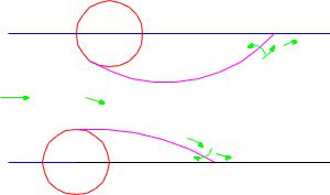
(Roberts, 1962, 1966) considered both a single and a double row of cylinders normal to flow. His analysis was limited to in-flow motion (experiments indicated that instability was purely in the in-flow direction). Roberts assumed that the flow downstream of two-adjacent cylinders could be represented by two wake regions, one large and one small, and a jet between them as shown in Figure 1.
Downstream
Cylinder
Imaginary |
|
Entrainment |
Boundary |
|
|
|
|
|
|
Large Wake |
|
V |
Vg |
|
|
|
|
|
Jet |
|
|
Small |
|
|
Wake |
|
Imaginary |
Upstream |
Entrainment |
Boundary |
|
|
Cylinder |
|
|
|
|
Fig. 1. Idealized model of the jet-flow between two cylinders in a staggered row of cylinders (Roberts, 1962).
Considering a downstream cylinder moving upstream; as the two cylinders cross, insufficient fluid flows in to the large wake region to maintain the entrainment, causing the wake to shrink and the jet to switch directions. Roberts has given the flow equation of motion for a cylinder or tube in a row.
d 2 x |
2 |
dx |
x |
V 2 |
|
|
|
|
|
0.717 |
|||
d 2 |
d |
2m n2 |
||||
|
|
|
1 Cpb (x, 2 |
|
nD |
1 |
Cpb |
|
dx |
(1) |
||
|
V |
|
|
|
|
||||
|
|
||||||||
|
|
|
|
|
mean d |
|
|||
where Cpb |
is the base pressure coefficient, is non-dimensional time t n , |
D is the tube |
||
diameter, |
n is the natural frequency, x is the in-flow cylinder displacement, |
|
is the |
|
damping |
factor or ratio, is the logarithmic decrement, and m is mass |
of |
the |
tube. |
Equation 1 was solved using the method of Krylov and Bogoliubov (Minorsky, 1947) giving
V , the velocity just sufficient to initiate limit cycle motion for any |
m / D2 . Neglecting |
|||||
c |
|
|
|
|
|
|
unsteady terms and fluid damping, the solution reduces to |
|
|||||
|
|
V |
|
m |
0.5 |
(2) |
|
|
c |
K |
|
|
|
|
|
|
|
|
|
|
|
|
D |
|
D2 |
|
|
|
|
n |
|
|
||
where is the ratio |
of fluid-elastic |
frequency to structural frequency, which is |
||||
approximately 1.0 and |
is the fluid density. This has the same form as the classical |
|||||
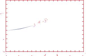
Connors equation (Blevins, 1979). Figure 2 presents Robert's experimental data for pitch-to- dia. ratio ( P / D 1.5 ), showing a good agreement with this theoretical model.
Cross-Flow-Induced-Vibrations in Heat Exchanger Tube Bundles: A Review |
79 |
Vc /εωnD
mδ/ρD2
___ Solution including time for jet reversal and aerodynamic damping
- - - Solution assuming instantaneous jet reversal but still including aerodynamic damping
___ Solution assuming instantaneous jet reversal and neglecting aerodynamic dampingRoberts' experimental results
Fig. 2. Theoretical stability boundary for fluid-elastic instability obtained by Roberts for a single flexible cylinder in a row of cylinders (Roberts, 1966).
2.2.2 Quasi-static models
Using a quasi-static analysis, (Connors & Parrondo, 1970) and later (Dalton & Helfinstine, 1971) developed the fluid-elastic instability prediction for cylinders (single row of cylinders) subjected to cross-flow. Connors measured the fluid forces instead of predicting these using pitch to dia. ratio of P/D=1.41. He observed many different model patterns at instability, but suggested that the most dominant was elliptical motion (whirling). Using the measured fluid stiffness, Connors obtained energy balances in the in-and cross-flow directions, which must be satisfied simultaneously giving
|
Vpc |
|
|
m |
|
0.5 |
(3) |
|
|
K |
|
|
|
||
|
fnD |
D |
2 |
||||
|
|
|
|
|
|
||
where K is the so-called Connors constant, |
fn is the frequency of oscillation.Vpc |
is the so- |
|||||
called pitch velocity given by |
|
|
|
|
|
|
|
|
Vpc |
|
VP |
|
|
(4) |
|
|
P D |
|
|||||
|
|
|
|||||
where P being the centre-to-centre inter cylinder pitch
(Blevins, 1974) has derived Equation 3 by assuming that the fluid forces on any cylinder are due to relative displacements between itself and its neighboring cylinders. Later, (Blevins, 1979) modified his original analysis to account for flow dependent fluid damping giving
80 |
|
|
|
|
|
|
|
Nuclear Power Plants |
|
Vpc |
|
m |
|
|
1/ 2 |
1/ 2 |
|
|
|
K |
|
|
2 |
( x y ) |
|
(5) |
|
fnD |
D |
2 |
|||||
|
|
|
|
|
|
|
where x and y are total damping factors in the in-and cross-flow directions.
2.2.3 In viscid model
Despite the obviously viscous nature of the interstitial flow through arrays of cylinders, the compactness of some arrays suggests that the cylinder wake regions are small, especially for normal triangular arrays with small P/D (Price, 1995). Hence under this assumption wake regions are neglected and flow is treated as inviscid. Many solutions based upon potential flow theory have been given, including (Dalton & Helfinstine, 1971), (Dalton, 1980), (Balsa, 1977), (Paidoussis et al., 1984), (Vander Hoogt & Van Compen, 1984) and (Delaigue & Planchard, 1986). The results obtained from potential flow analyses are somewhat discouraging (Price, 1995). Recent flow visualizations suggest that even though the wake regions are small, the interstitial flow is more complex than that accounted for in these analyses.
2.2.4 Unsteady models
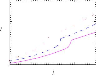
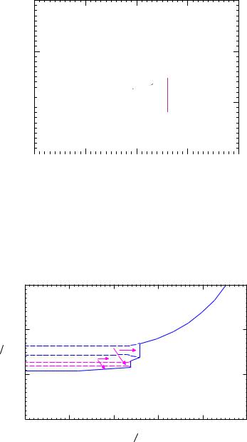
The unsteady models measure the unsteady forces on the oscillating cylinder directly. (Tanaka & Takahara, 1980, 1981) and (Chen, 1983) have given theoretical stability boundary for fluid-elastic instability as shown in Figures 3 and 4 respectively.
|
1000 |
|
|
|
|
|
100 |
|
|
|
|
Vpc |
fn D |
|
|
|
|
|
10 |
|
|
|
|
|
1 |
|
|
|
|
|
|
|
102 |
3 |
4 |
|
1 |
10 |
10 |
10 |
|
|
|
|
m D 2 |
|
|
____ =0.01
– – – =0.03
Fig. 3. Theoretical stability boundary for fluid-elastic instability for an in-line square array, P/D=1.33, obtained by (Tanaka & Takahara, 1980, 1981).
Cross-Flow-Induced-Vibrations in Heat Exchanger Tube Bundles: A Review |
81 |
1000
100
Vpc fn D
Unstable


 Stable 10


Unstable
1
|
|
|
|
|
|
|
0.01 |
0.1 |
1 |
10 |
102 |
||
mδ ρD 2
ρD 2
– – –Theoretical solution showing multiple instability boundaries
____Practical stability boundary
Fig. 4. Theoretical stability for fluid-elastic instability predicted by (Chen, 1983), for a row of cylinders with P/D=1.33.
2.2.5 Semi-analytical model
Out of many semi analytical models, Figure 5 shows theoretical stability boundary for fluidelastic instability obtained by (Lever & Weaver, 1986).
|
1000 |
|
|
|
|
|
|
100 |
|
|
|
|
|
|
|
Unstable |
|
|
|
|
Vpc |
fn D |
|
Stable |
|
|
|
|
|
Unstable |
|
|
|
|
|
10 |
|
|
|
|
|
|
1 |
|
|
|
2 |
3 |
|
0.01 |
0.1 |
1 |
10 |
||
|
10 |
10 |
||||
|
|
|
m |
D 2 |
|
|
– – –Theoretical solution showing multiple instability boundaries
____Practical stability boundary
Fig. 5. Theoretical stability boundary for fluid-elastic instability obtained by (Lever & Weaver, 1986) for single flexible cylinder in a parallel triangular array with P/D=1.375.

82 Nuclear Power Plants
2.2.6 Quasi-steady model
(Price, 1995) remarks that Fung and Blevins have concluded that quasi-steady fluid
dynamics is valid provided |
V |
10 ; however, experiments by Price, Paidoussis and |
|
fnD |
|||
|
|
Sychterz and others suggest that for closely spaced bodies the restriction on the use of quasisteady fluid dynamics is much more severe than that suggested by Fung or Blevins. (Gross, 1975) carried out first quasi-steady analysis of cylinder arrays subjected to cross-flow concluding that instability in cylinder arrays is due to two distinct mechanisms: negative damping and stiffness controlled instability.
2.2.7 Computational fluid dynamic (CFD) models
The CFD solutions applicable to fluid-elastic instability and other problem areas of flowinduced vibrations are increasing. These include (Marn and Catton, 1991) and (Planchard & Thomas, 1993).
2.2.8 Non-linear models
The first non-linear model was given by (Roberts, 1962, 1966), who employed Krylov and Bogoliubov method (Minorsky, 1947) of averaging to solve the non-linear equations. Twomotivating forces have been remarked by (Price, 1995) for non-linear analyses. Firstly because of manufacturing tolerances and thermal constraints, there are likely to be small clearances between heat exchanger tubes and intermediate supports. Hence, large lengths of unsupported tubes, having very low natural frequencies. These low-frequencies may suffer from fluid-elastic instability at relatively low Vpc . A second and more academic motivating force for these non-linear analysis has been to investigate the possibility of Choatic behavior of tube motion.
2.2.9 Recent researches in fluid-elastic instability
A summary of some recent efforts on the analysis of fluid-elastic instability in heat exchanger and steam generator tube bundles is given in Table 4.
Researchers |
Flow |
Analysis |
Frequency |
Span type |
Model type |
Remarks |
|
(phase) |
type |
||||||
|
|
|
|
|
|
|
|
|
|
|
|
|
|
Tube |
|
|
|
|
|
|
Comparison |
supports |
|
|
|
Simulation |
Up to |
Loosely |
with several |
interaction |
|
(Hassan |
Single |
time |
parameters |
||||
(linear/ |
90Hz |
supported |
Impact Force |
||||
et al., 2011) |
phase |
domains |
|||||
non-linear) |
approx. |
multispan |
Contact rates |
||||
|
|
fluid force |
|||||
|
|
|
|
|
Normal wave |
||
|
|
|
|
|
model |
||
|
|
|
|
|
rate |
||
|
|
|
|
|
|
||
|
|
|
|
|
|
considered. |
|
Cross-Flow-Induced-Vibrations in Heat Exchanger Tube Bundles: A Review |
83 |
|
||||||
|
|
|
|
|
|
|
|
|
|
|
Researchers |
Flow |
Analysis |
Frequency |
Span type |
Model type |
Remarks |
|
|
|
(phase) |
type |
|
||||||
|
|
|
|
|
|
|
|
|
|
|
|
|
|
|
|
|
|
Dimensionless |
|
|
|
|
|
|
|
|
|
flow velocity |
|
|
|
|
Experimental |
|
|
|
and mass- |
|
|
|
|
|
|
|
|
damping |
|
||
|
|
|
test section |
|
|
|
|
||
|
|
|
Frequency |
Cantilevered |
Normal |
parameter |
|
||
|
(Sim & |
Two |
consists of |
|
|||||
|
Range |
flexible |
square tube |
consideration |
|
||||
|
Park, 2010) |
phase |
flexible and |
|
|||||
|
8.25-12 Hz |
cylinders |
bundles |
s and fluid- |
|
||||
|
|
|
rigid |
|
|
|
|
elastic |
|
|
|
|
cylinders |
|
|
|
|
||
|
|
|
|
|
|
instability |
|
||
|
|
|
|
|
|
|
|
|
|
|
|
|
|
|
|
|
|
coefficients |
|
|
|
|
|
|
|
Tube banks |
|
considerations |
|
|
|
|
|
|
|
|
Onset of |
|
|
|
(Ishihara & |
|
|
|
|
such as |
|
fluid-elastic |
|
|
Single |
Experimental |
|
boilers and |
Experimental |
instability |
|
||
|
Kitayama, |
|
|
||||||
|
2009) |
phase |
|
|
|
heat |
|
and geometry |
|
|
|
|
|
|
exchangers in |
|
relationship |
|
|
|
|
|
|
|
|
|
|
||
|
|
|
|
|
|
power plant |
|
considerations |
|
|
|
Single & |
|
|
|
|
Fully flexible |
Displacement |
|
|
|
two |
|
|
|
|
tube arrays |
and damping |
|
|
|
|
|
Frequency |
|
mechanisms |
|
||
|
|
phase |
|
|
|
and single |
|
||
|
(Mitra |
|
|
range |
|
Critical flow |
|
||
|
(Air- |
Experimental |
|
flexible tube |
|
||||
|
et al., 2009) |
7.6 - 13.74 |
|
velocity was |
|
||||
|
|
water & |
|
|
Hz |
|
(Normal |
found |
|
|
|
air-steam |
|
|
|
square |
|
||
|
|
|
|
|
|
proportional |
|
||
|
|
flow) |
|
|
|
|
array) |
|
|
|
|
|
|
|
|
to tube arrays |
|
||
|
|
|
|
|
|
Second array |
|
|
|
|
|
|
|
|
Excitation |
|
|
|
|
|
(Mahon & |
Single |
Experimental |
flexible tube |
Normal |
Time delay |
|
||
|
Meskell, |
phase |
|
= 1.32 |
frequency |
with electro- |
Triangular |
considerations |
|
|
2009) |
|
|
6.62 Hz |
magnetic |
|
|
|
|
|
|
|
|
damper |
|
|
|
||
|
|
|
|
|
|
|
|
Critical |
|
|
|
|
|
|
|
|
|
velocity |
|
|
|
|
Modeling |
|
|
|
predictions |
|
|
|
|
|
|
|
Time |
dependent |
|
||
|
(Hassan & |
|
and |
|
|
|
|
||
|
Single |
|
Up to |
|
domain |
upon i.e. |
|
||
|
Hayder, |
phase |
simulation |
60 Hz |
|
modeling of |
sensitive to |
|
|
|
2008) |
(Linear/ |
|
|
|||||
|
|
|
|
tube forces |
both gap size |
|
|||
|
|
|
Non-linear) |
|
|
|
|||
|
|
|
|
|
|
and |
|
||
|
|
|
|
|
|
|
|
|
|
|
|
|
|
|
|
|
|
turbulence |
|
|
|
|
|
|
|
|
|
level |
|
|
|
Two |
Experimental |
|
|
|
Hydro |
|
|
|
(Chung & |
phase |
|
= 1.633 |
Strouhal |
Cantilevered |
|
dynamic |
|
|
Void |
100 |
number |
straight tube |
Experimental |
coupling |
|
||
|
Chu, 2006) |
|
|||||||
|
|
Fraction |
50 m |
Water |
0.15-0.19 |
bundles |
|
effects |
|
|
|
10-95% |
/ |
|
|
|
consideration |
|
|
|
|
|
Head |
|
|
|
|
|
|

84 |
Nuclear Power Plants |
Researchers |
Flow |
Analysis |
Frequency |
(phase) |
type |
||
|
|
|
|
|
|
Experimental |
|
|
Single |
Wind tunnel |
|
(Mureithi |
phase |
partially |
18.74 Hz |
et al., 2005). |
0.44% |
fixed flexible |
|
|
damping |
array |
|
|
|
= 1.633 |
|
Span type |
Model type |
Remarks |
|
|
|
|
|
Investigation |
Preferentially |
Rotated |
of stability |
triangular |
behavior and |
|
flexible |
array |
AVB’s |
|
||
|
|
considerations |
|
|
|
Table 4. A summary of recent fluid-elastic instability research
2.3 Vorticity induced instability
Flow across a tube produces a series of vortices in the downstream wake formed as the flow separates alternatively from the opposite sides of the tube. This shedding of vortices produces alternating forces, which occur more frequently as the velocity of flow increases. For a single cylinder, frequency of vortex shedding fvs is given below by a dimensionless Strouhal number S .
fvs |
SV |
(6) |
|
D |
|||
|
|
where V is the flow velocity and D is the tube diameter. For a single cylinder, the vortex shedding Strouhal number is a constant with a value of about 0.2 (Chenoweth, 1993). Vortex shedding occurs for the range of Reynolds number 100 < Re <5x10⁵ and > 2 x 10⁶ whereas it dies out in-between. The gap is due to a shift of the flow separation point in vortices in the intermediate transcritical Reynolds number range. Vortex shedding can excite tube vibration when it matches with the natural frequency of the tubes. For tube banks with vortex shedding, Strouhal number is not constant, but varies with the arrangement and spacing of tubes, typical values for in-line and staggered tube bundle geometries are given in (Karaman, 1912, Lienhard, 1966). Strouhal numbers for in-line tube banks are given in Figure 6.
The vortex shedding frequency can become locked-in to the natural frequency of a vibrating tube even when flow velocity is increased (Blevins, 1977). Earlier on, the mechanism of vortex shedding has been investigated by a number of researchers. These include Sipvack (Sipvack, 1946) and, Thomas and Kraus (Thomas & Kraus, 1964) who investigated the vortex shedding of two cylinders arranged parallel and perpendicular to flow direction respectively. Grotz and Arnold (Groth & Arnold, 1956) measured for the first time systematically the vortex shedding frequencies in in-line tube bank for various tube spacing ratios.
The cause of vorticity excitation has been disputed in literature (Owen, 1965), but recent studies of (Weaver, 1993) and, (Oengoren & Ziada, 1993) have confirmed its cause of existence as periodic vortex formation. Vorticity shedding can cause tube resonance in liquid flow or acoustic resonance of the tube bundles or acoustic resonance of the tube bundles' containers in gas flows (Oengoren & Ziada, 1995). (Chen, 1990), (Zaida & Oengoren, 1992) and (Weaver, 1993) have summarized the recent research efforts targeted at improvement in Strouhal number charts for vortex shedding and acoustic resonance for inline tube bundles.