

NUCLEAR POWER PLANTS
.pdfThe Gap Measurement Technology and Advanced RVI |
145 |
Installation Method for Construction Period Reduction of a PWR |
mockup. Thus, it was designed to be different from the actual size. The RV upper flange was simply designed.
The RV upper flange-face was assembled with the CSB and was applied to actual conditions in the same manner. The RV cylinder was designed with a thin plate, including a RV corestabilizing lug. The height of the RV mockup was minimized to 2,665 mm.
The assembled parts of the RV core-stabilizing lugs, the RV core stop lug, and the shim were designed to be identical to their real-life counterparts.
Six supports of 70 cm in height were attached to the bottom of the RV mockup to monitor the condition of the measurement sensors. The lifting lugs were welded onto the RV upper flange to facilitate assembly and separation from the CSB mockup.
Fig. 17 and Fig. 18 show the designed 3D model and an image of the manufactured RV mockup.
Fig. 17. 3D model of the RV mockup
Fig. 18. Image of the manufactured RV mockup
3.2.4 Design of the CSB mockup
The CSB outer diameter is identical to that of its real-life counterpart. However, the CSB inner diameter, not related to the measurement, was designed to be thinner, making it a light CSB mockup. Thus, it was designed to be different from the actual size.
The conditions of the CSB flange in contact with the RV upper flange were designed according to actual conditions. The CSB cylinder was designed with a thin plate including the CSB snubber lug. The height of the CSB mockup was minimized to 1,618 mm. The CSB

146 |
Nuclear Power Plants |
snubber lugs were both designed in keeping with their actual shapes and were welded onto the CSB. The lifting lugs were welded onto the CSB flange to facilitate assembly and separation from the RV mockup. A stand for the installation of the remote measurement system was designed on the inside of the CSB mockup.
Fig. 19 and Fig. 20 show the designed 3D model and an image of the manufactured CSB mockup.
Fig. 19. 3D model of the CSB mockup
Fig. 20. Image of the manufactured CSB mockup
3.3 Experiment and result 3.3.1 Experiment
One difference between the remote measurement method and the hand-measurement method is that measurement had to be done using the remote measurement system after assembly of the CSB on the RV. An additional difference was that it was necessary to attach a gauge block to the RV core-stabilizing lug before assembly of the CSB to overcome the length-measurement limit of the remote measurement system.
The measurement value of the gap between the RV core-stabilizing lug and the CSB snubber lug is typically measured to a maximum 49 mm in the construction sites of nuclear power plants, but the maximum measurement range of the measurement sensor in the remote measurement system was 20 mm.
Therefore, the remote measurement method required twelve gauge blocks of 35 mm to measure 72 points simultaneously.
The experimental procedure of the remote measurement system using the RV mockup and the CSB mockup is as follows:
The Gap Measurement Technology and Advanced RVI |
147 |
Installation Method for Construction Period Reduction of a PWR |
-Widths of six RV core-stabilizing lugs and twelve gauge blocks of 35 mm made using a micrometer were measured and attached to twelve gauge blocks to the right and the left of the six RV core-stabilizing lugs.
-The inside lengths of the CSB snubber lugs, the locations of the contact of the RV corestabilizing lug with the CSB snubber lug, were measured using a cylinder gauge.
-The remote measurement system was installed on a stand inside the CSB mockup. The stand is used to simplify the LSS in RVI.
-72 sensors assembled with 72 threaded connection jigs were inserted and fixed at 72 holes for measurement of the CSB snubber lugs.
-Three channel boxes are connected to air-hoses, signal cables, and electric power cables.
-The software program for remote measurement should be tested and measurement sensors should be confirmed as being capable of normal operation using the remote control computer.
-To set a start-point of the measurement sensors, six zero-point adjustment devices were installed between the left and the right areas of the CSB snubber lugs and were adjusted to the zero point. After the zero-point adjustment, the six zero-point adjustment devices were disconnected from the CSB snubber lugs.
-After the CSB mockup of the RV mockup was assembled, the gaps between the RV core stabilizing lugs and the CSB snubber lugs were measured using the remote measurement system.
The measurement test, using the remote measurement system, was carried out with the assembly and disassembly of the RV mockup and the CSB mockup three times in succession.
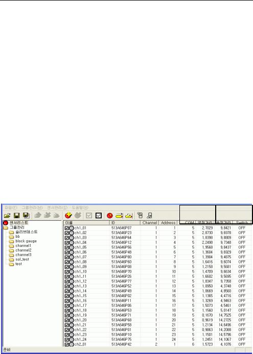
Fig. 21 shows a computer screen detailing the gaps as acquired by the remote measurement system.
|
|
0-Point |
Measured |
|
|
Length [mm] |
Length [mm] |
|
|||
List of Sensors |
|
Name |
|
Group Management |
|
|
|
Sleeve Test |
|
|
|
|
|
|
|
Fig. 21. Screen showing measurement results of the remote measurement system
148 |
Nuclear Power Plants |
3.3.2 Result
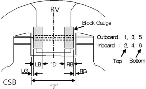
The ground plan for the gap between the RV and the CSB as measured by the remote measurement system is shown in Fig. 22.
Table 3 shows a comparison of the data by the remote measurement system and the handmeasurements.
The “Total” value, data by the remote measurement system, denotes the sum of the left gap (LG) and the right gap (RG), the left block-gauge length (LB) and the right block-gauge length (RB), and the width of the RV core-stabilizing lug (D). The “J” value represents the hand-measurement data using a micrometer. Therefore, the “Total – J” value denotes the error between the remote measurement system data and the hand-measurement data.
Table 3 now shows that the remote measurement system has high accuracy as the maximum error is only 0.0669 mm. The maximum error is smaller than 0.127 mm of acceptance criteria.
Fig. 22. Ground plan for the gap of between the RV and the CSB
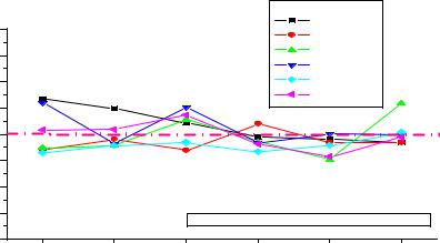
The differences between the Total values and the J values are shown in Fig. 23.
On the other hand, on the basis of the permissible range, which was set to 0.381 – 0.508 mm, if there is a difference in the width that is within 0.127 mm, the requirements are considered to be satisfied. Errors in the measurement data that was used in the remote measurement system in the experiment and analyses did not exceed 0.127 mm.
Therefore, through this experiment and as demonstrated by the results, the remote measurement system was demonstrated to have reliability and the required applicability for deployment in the construction sites of nuclear power plants.

|
The Gap Measurement Technology and Advanced RVI |
|
|
|
|
|
|
149 |
|
|||||||||||||||
|
Installation Method for Construction Period Reduction of a PWR |
|
|
|
|
|
|
|
||||||||||||||||
|
|
|
|
|
|
|
|
|
|
|
|
|
|
|
|
|
|
|
|
|
|
|
|
|
|
Location |
LG + |
|
|
LB + |
|
|
D |
|
|
+ RB |
|
|
+ RG |
|
|
= |
|
|
Total |
J |
Total - J |
|
|
|
|
|
|
|
|
|
|
|
|
|
|
|
(Error) |
|
||||||||||
|
|
|
|
|
|
|
|
|
|
|
|
|
|
|
|
|
|
|
|
|
|
|
|
|
|
|
|
|
|
|
|
|
|
|
|
|
|
|
|
|
|
|
|
|
|
|
|
|
|
|
|
1 |
9.9007 |
|
34.885 |
|
152.150 |
|
34.895 |
|
9.5612 |
|
= |
|
241.3919 |
241.3250 |
0.0669 |
|
||||||
|
|
2 |
9.7528 |
|
34.900 |
|
152.130 |
|
34.895 |
|
9.6764 |
|
= |
|
241.3542 |
241.3050 |
0.0492 |
|
||||||
|
0° |
3 |
9.8675 |
|
34.890 |
|
152.120 |
|
34.905 |
|
9.5639 |
|
= |
|
241.3464 |
241.3250 |
0.0214 |
|
||||||
|
4 |
9.6571 |
|
34.965 |
|
152.110 |
|
34.905 |
|
9.6678 |
|
= |
|
241.3049 |
241.3100 |
-0.0051 |
|
|||||||
|
|
|
|
|
|
|
|
|
||||||||||||||||
|
|
5 |
9.8546 |
|
34.855 |
|
152.125 |
|
34.875 |
|
9.6056 |
|
= |
|
241.3152 |
241.3250 |
-0.0098 |
|
||||||
|
|
6 |
9.7016 |
|
34.865 |
|
152.100 |
|
34.875 |
|
9.7631 |
|
= |
|
241.3047 |
241.3200 |
-0.0153 |
|
||||||
|
|
1 |
4.3944 |
|
34.885 |
|
152.390 |
|
34.900 |
|
14.7650 |
|
= |
|
241.3344 |
241.3650 |
-0.0306 |
|
||||||
|
|
2 |
4.8742 |
|
34.895 |
|
152.385 |
|
34.900 |
|
14.2862 |
|
= |
|
241.3404 |
241.3500 |
-0.0096 |
|
||||||
|
60° |
3 |
4.4628 |
|
34.900 |
|
152.420 |
|
34.910 |
|
14.6466 |
|
= |
|
241.3394 |
241.3700 |
-0.0306 |
|
||||||
|
4 |
4.9950 |
|
34.905 |
|
152.390 |
|
34.905 |
|
14.1700 |
|
= |
|
241.3650 |
241.3450 |
0.0200 |
|
|||||||
|
|
|
|
|
|
|
|
|
||||||||||||||||
|
|
5 |
4.5724 |
|
34.875 |
|
152.435 |
|
34.865 |
|
14.6027 |
|
= |
|
241.3501 |
241.3650 |
-0.0149 |
|
||||||
|
|
6 |
5.0382 |
|
34.885 |
|
152.410 |
|
34.875 |
|
14.1214 |
|
= |
|
241.3296 |
241.3450 |
-0.0154 |
|
||||||
|
|
1 |
4.0993 |
|
34.900 |
|
152.250 |
|
34.890 |
|
15.1549 |
|
= |
|
241.2942 |
241.3200 |
-0.0258 |
|
||||||
|
|
2 |
3.8661 |
|
34.895 |
|
152.240 |
|
34.895 |
|
15.3632 |
|
= |
|
241.2593 |
241.2800 |
-0.0207 |
|
||||||
|
120° |
3 |
4.1366 |
|
34.905 |
|
152.240 |
|
34.895 |
|
15.1916 |
|
= |
|
241.3682 |
241.3400 |
0.0282 |
|
||||||
|
4 |
3.8756 |
|
34.905 |
|
152.210 |
|
34.900 |
|
15.3849 |
|
= |
|
241.2755 |
241.2900 |
-0.0145 |
|
|||||||
|
|
|
|
|
|
|
|
|
||||||||||||||||
|
|
5 |
4.1408 |
|
34.875 |
|
152.220 |
|
34.870 |
|
15.1761 |
|
= |
|
241.2819 |
241.3300 |
-0.0481 |
|
||||||
|
|
6 |
3.9372 |
|
34.875 |
|
152.205 |
|
34.880 |
|
15.4613 |
|
= |
|
241.3585 |
241.3000 |
0.0585 |
|
||||||
|
|
1 |
7.0775 |
|
34.905 |
|
152.145 |
|
34.890 |
|
12.3671 |
|
= |
|
241.3846 |
241.3250 |
0.0596 |
|
||||||
|
|
2 |
7.1105 |
|
34.900 |
|
152.125 |
|
34.875 |
|
12.2970 |
|
= |
|
241.3075 |
241.3250 |
-0.0175 |
|
||||||
|
180° |
3 |
7.2694 |
|
34.900 |
|
152.175 |
|
34.900 |
|
12.1571 |
|
= |
|
241.4015 |
241.3500 |
0.0515 |
|
||||||
|
4 |
7.2975 |
|
34.895 |
|
152.150 |
|
34.885 |
|
12.0841 |
|
= |
|
241.3116 |
241.3275 |
-0.0159 |
|
|||||||
|
|
|
|
|
|
|
|
|
||||||||||||||||
|
|
5 |
7.5123 |
|
34.850 |
|
152.160 |
|
34.855 |
|
11.9887 |
|
= |
|
241.3660 |
241.3650 |
0.0010 |
|
||||||
|
|
6 |
7.5585 |
|
34.850 |
|
152.140 |
|
34.845 |
|
11.9393 |
|
= |
|
241.3328 |
241.3350 |
-0.0022 |
|
||||||
|
|
1 |
3.0665 |
|
34.895 |
|
152.220 |
|
34.890 |
|
16.2133 |
|
= |
|
241.2848 |
241.3200 |
-0.0352 |
|
||||||
|
|
2 |
3.4621 |
|
34.900 |
|
152.090 |
|
34.895 |
|
15.9112 |
|
= |
|
241.2583 |
241.2800 |
-0.0217 |
|
||||||
|
240° |
3 |
3.1894 |
|
34.905 |
|
152.205 |
|
34.900 |
|
16.1000 |
|
= |
|
241.2994 |
241.3150 |
-0.0156 |
|
||||||
|
4 |
3.5021 |
|
34.905 |
|
152.080 |
|
34.905 |
|
15.8700 |
|
= |
|
241.2621 |
241.2950 |
-0.0329 |
|
|||||||
|
|
|
|
|
|
|
|
|
||||||||||||||||
|
|
5 |
3.3227 |
|
34.865 |
|
152.195 |
|
34.865 |
|
16.0655 |
|
= |
|
241.3132 |
241.3350 |
-0.0218 |
|
||||||
|
|
6 |
3.6515 |
|
34.865 |
|
152.085 |
|
34.875 |
|
15.8272 |
|
= |
|
241.3037 |
241.3000 |
0.0037 |
|
||||||
|
|
1 |
6.6439 |
|
34.875 |
|
152.265 |
|
34.895 |
|
12.6747 |
|
= |
|
241.3536 |
241.3450 |
0.0086 |
|
||||||
|
|
2 |
6.5915 |
|
34.895 |
|
152.130 |
|
34.900 |
|
12.8177 |
|
= |
|
241.3342 |
241.3250 |
0.0092 |
|
||||||
|
300° |
3 |
6.6015 |
|
34.890 |
|
152.260 |
|
34.905 |
|
12.7303 |
|
= |
|
241.3868 |
241.3500 |
0.0368 |
|
||||||
|
4 |
6.5128 |
|
34.905 |
|
152.145 |
|
34.905 |
|
12.8487 |
|
= |
|
241.3165 |
241.3350 |
-0.0185 |
|
|||||||
|
|
|
|
|
|
|
|
|
||||||||||||||||
|
|
5 |
6.5463 |
|
34.860 |
|
152.240 |
|
34.860 |
|
12.8112 |
|
= |
|
241.3175 |
241.3600 |
-0.0425 |
|
||||||
|
|
6 |
6.5746 |
|
34.870 |
|
152.125 |
|
34.865 |
|
12.8949 |
|
= |
|
241.3295 |
241.3350 |
-0.0055 |
|
||||||
Table 3.Comparison of data by remote measurement system and hand-measurement
150 |
Nuclear Power Plants |
|
0 |
. 2 0 |
|
|
|
0 0 |
d a ta |
|
|
|
|
6 0 0 |
d a ta |
||
|
0 |
. 1 5 |
|
|
|
1 2 0 0 |
d a ta |
|
|
|
|
1 8 0 0 |
d a ta |
||
|
|
|
|
|
|
||
|
0 . 1 0 |
|
|
|
2 4 0 0 d a ta |
||
|
|
|
|
|
|
3 0 0 0 |
d a ta |
Difference(mm) |
0 |
. 0 5 |
|
|
|
|
|
0 |
. 0 0 |
|
|
|
|
|
|
- 0 . 0 5 |
|
|
|
|
|
||
|
|
|
|
|
|
|
|
|
- 0 . 1 0 |
|
|
|
|
|
|
|
- 0 . 1 5 |
|
( L G + L B + D + R B + R G ) - J = D if f . |
||||
|
|
|
|
||||
|
- 0 . 2 0 |
|
|
|
|
|
|
|
|
1 |
2 |
3 |
4 |
5 |
6 |
|
|
|
|
S e n s o r |
P o s itio n |
|
|
Fig. 23. Differences between the Total values and the J values
3.4 Conclusion
A system was successfully developed that can measure the gaps between the RV corestabilizing lugs and the CSB snubber lugs remotely for RVI-modularization. To confirm the reliability of this method and its applicability to construction sites, the measurement system was designed, manufactured, and tested it using an RV mockup and CSB mockup.
It is therefore concluded that the remote measurement system reduces the construction period by nearly two months or more compared to the existing method of hand measurements.
As the developed remote measurement system can be used at actual construction sites.
4. Development of an improved installation procedure and schedule of RVI modularization
4.1 Development of an improved installation procedure for RVI modularization
Under the existing installation procedure, six snubber shims were assembled between the RV core-stabilizing lugs and the CSB snubber lugs after alignment of the CSB and the RV. Subsequently, assembly and flexure welding of the LSS and the CS were conducted. The new and improved installation procedure for RVI modularization was developed allowing assembly and flexure welding of the LSS and the CS to be performed before the main installation process. Alignment of the CSB assembly and the RV and assembly of the snubber shims were undertaken during the main installation process.
The improved installation procedure for RVI modularization (Ko, 2011) appears in Table 4 as order 1 and order 3. A detailed explanation is given below of the flexure welding of the LSS and the CS in the CSB as well as of the alignment and installation of the snubber shims of the CSB assembly and the RV.
The Gap Measurement Technology and Advanced RVI |
151 |
||
Installation Method for Construction Period Reduction of a PWR |
|||
|
|
|
|
|
Order |
RVI installation procedure |
Remark |
|
|
|
|
|
1 |
Assembly of the LSS and the CS in the CSB, Flexure welding |
Improvement |
|
2 |
Welding of the flow baffle in the RV |
|
|
3 |
Alignment of the CSB assembly and the RV, Installation of snubber |
Improvement |
|
shims |
||
|
|
|
|
|
4 |
Installation of the CSB assembly in the RV |
|
|
5 |
Installation and alignment of the UGS |
|
|
6 |
Installation and alignment of the RV head |
|
|
7 |
Installation of alignment keys, dowel pins and guide lugs insert |
|
|
8 |
Final alignment, Installation of head down ring and HJTC tube |
|
Table 4. Improved installation procedure for RVI modularization
4.1.1 Alignment of the CSB and RV and calculation of the dimensions of the snubber shim
1.The dimensions between the RV outlet nozzle and the reactor coolant loop (RCL) were measured after the welding of the RCL. They were recorded along with the measured dimensions before the welding. The widths of the RV core-stabilizing lugs were also measured.
2.The measured positions were marked on RV keyways and the relative positions of the keyways on the RV centerline were measured using the widths and vertical degrees.
3.The target-hole positions of the RV flange on the RV centerline and the dimensions of the gauge blocks of the RV core stabilizing lug were also measured. Here, the dimensions of the required measurements were the heights and widths of the gauge blocks.
4.Before installation of the gauge blocks, the integrity of the RV core-stabilizing lugs and the cap screws was checked. Neolube was applied twice on both the threaded surfaces on the cap screws and the surfaces of the bearings.
4.1.2 Installation of the gauge block
1.Gauge blocks were installed and the cap screws were then tightened. They needed to be tightened according to a three-step tightness method, as follows: 160, 213 and 266 ft-lbs. The final torque was 256 - 276 ft-lbs and the tightness sequence was as follows:
2.The number of cap screws was 1, 2, 3, and 4 from top to bottom. The tightness sequence of step 1 was 2, 3, 1, and 4, and the torque was 160 ft-lbs.
3.The tightness of step 2 was identical to that of 2) and the torque was 213 ft-lbs.
4.The tightness of step 3 was identical to that of 2) and the torque was 266 ft-lbs.
5.The cap screws were unscrewed in the reverse sequence of the tightness sequence: 4, 1, 3, and 2.
6.One more time, the tightness was carried out by the sequence of 2), 3), and 4).
7.The remaining gauge blocks were installed on the CSB snubber lugs according to the sequence of 2), 3), 4), 5), and 6). After installation of the gauge blocks, the gaps between the upper part and the lower part were uniformly maintained at 0.1016 mm.
152 |
Nuclear Power Plants |
4.1.3 Dimensions of the CSB Snubber Lug
1.After installation of the gauge blocks, all widths of the gauge blocks at the same six intervals were measured. Subsequently, the dimensions of the CSB snubber lugs were measured. The measured parts of the CSB snubber lugs were the inside widths of both of their surfaces. In total, six holes of the CSB snubber lugs were measured.
2.The measured positions of the CSB keyway were marked and the widths measured.
3.Four dummy alignment keys (DAKs) were installed on the RV keyways and adjusted so that they could be positioned within 0.254 mm of the RV centerline. The vertical degree of an RV head seating surface of a DAK was adjusted so that it could be positioned within 0.0254 mm/ft. The position of the DAK and the vertical degree were measured again.
4.1.4 Installation of the remote measurement system
1.In order to set up the remote measurement system inside the CSB assembly, three channel boxes were mounted in the CSB assembly. As shown in Fig. 15, the channel boxes were opened and 72 digital probes were taken out of the CSB assembly through spaces between the CSB and the LSS.
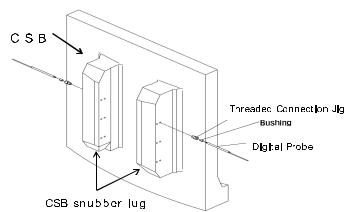
Fig. 24. Assembly of digital probe and threaded connection jig
2.As shown in Fig. 24, all 72 digital probes were installed the holes of the CSB snubber lugs after the digital probes were assembled with the threaded connection jigs. For this step, the digital probes were necessarily placed at 1 mm or more from the measured holes of the CSB snubber lug. Bolt tightening was done using a hexagonal wrench. The bolts numbered 1, 2, 3, and 4 were clockwise and the tightening order was 1, 3, 2, and 4. All remaining sensors were installed via the methods described above.
3.The electric power cords, air hoses, and signal cables between the channel boxes were connected and taken out of the RV. The air hoses were connected with an air compressor.
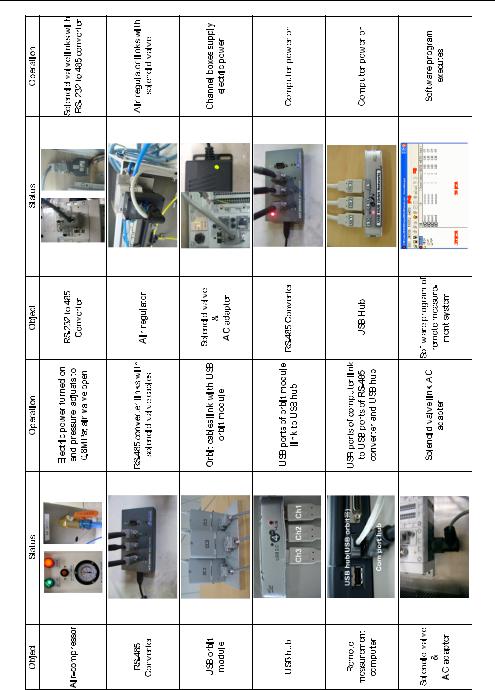
4.The signal cables were linked with a USB-orbit module and an RS-485 converter. The USB ports of the USB-orbit module were linked with a USB hub. The USB hub and USB ports of the RS-485 converter were connected to the USB ports of a remote measurement computer. Table 5 shows the remote measurement system guideline.
The Gap Measurement Technology and Advanced RVI |
153 |
Installation Method for Construction Period Reduction of a PWR |
Table 5. Remote measurement system guideline
154 |
Nuclear Power Plants |
5.Electric power supplies were checked in order with the remote measurement system first, followed by the air compressor, and then the remote measurement computer to verify whether or not the connections worked exactly according to the operating guide.
6.The air pressure was set to 0.8 – 1 bar using a software program on the remote measurement computer. At this stage, the digital probes had to be checked using a software program to verify whether or not they operated normally. Fig. 14 shows the configuration of the remote measurement system.
4.1.5 Zero-point adjustment of the remote measurement system and marking
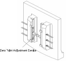
1.In order to attach a zero-point adjustment device firmly onto the CSB snubber lug, a zero-point adjustment plate and a connector on the gap control section were tightened. The remaining zero-point adjustment devices adhered to the CSB snubber lug as described above. Fig. 25 shows the zero-point adjustment device mounted on the CSB snubber lug.
2.Length measurement was done using the software program of the remote measurement computer. Measurements were taken five times. The average values were then used to set the zero-point data. When the setting of the zero-point data was complete, the zeropoint data were saved and recorded.
3.The zero-point adjustment device was detached from the CSB snubber lug and a marking tool was attached to the CSB snubber lug. Digital probes were stained with a red stamping ink and their correct operation was confirmed using the software program of the remote measurement computer. The remaining digital probes were executed in the same way.
4.The marking tool was removed from the CSB snubber lug and the channel boxes in the CSB assembly and air compressor were then separated from the air hoses, electric power cords, and signal cables connected to the remote measurement computer. The disconnected cords and cables had to be arranged so that a disturbance did not result from the combination of the RV and the CSB assembly. Fig. 26 shows the marking tool assembly attached onto the CSB snubber lug.
Fig. 25. Installation of zero point adjustment device