

NUCLEAR POWER PLANTS
.pdf7
Investigation on Two-Phase Flow Characteristics in Nuclear Power Equipment
Lu Guangyao, Ren Junsheng, Huang Wenyou, Xiang Wenyuan,
Zhang Chengang and Lv Yonghong
China Guangdong Nuclear Power Holding Co. Ltd.
China
1. Introduction
Two-phase flow exits in many nuclear power equipments, such as containment sump strainer, steam generator, steam turbine, control rod drive mechanism and so on. Experimental investigations are carried out to study the two-phase flow patterns and their transitions in these nuclear power equipments. And the results show that the two-phase flow patterns and their transitions are quite different from those in normal circular tubes.
For tube-bundle channel heat transfer enhancement technique, it has great advantages in high heat transfer efficiency and compact configuration without complex machining or additional surface processing, which has been successfully used in steam generator in nuclear power station and other industrial equipments. The characteristics of boiling flow and heat transfer have an important impact on these industrial equipments. It was found that heat transfer characteristics of fluid flowing in tube-bundle channels were different from those in circular tubes on account of the special geometric frame and different flow patterns in tube-bundle channels (Petigrew & Taylor, 1994). Boiling flow and heat transfer is a complex issue of twophase flow, and many studies have been conducted in this research area.
Experiments of boiling flow in tube-bundle channels were carried out in order to simulate boiling flow and heat transfer in fuel module of nuclear reactor (Bergles, 1981). The experimental results showed that there were many different aspects of flow patterns and their transitions in tube-bundle channels. Grant & Chisolm (1979) and Ma (1992) made studies of air-water two-phase flow in tube-bundle heat exchangers, in which the vertical flow and horizontal flow experiments were conducted respectively. Grant & Chisolm (1979) found that there were mist flow, bubbly flow, intermittent flow, stratified-mist flow and stratified flow in tub-bundle channels. But Ma (1992) detected stratified flow and wave flow in horizontal channels, and bubbly flow and intermittent flow in vertical channels, which was different from the results gained by Grant & Chisolm (1979). Chan & Shoukri (1987) conducted visualization experiments of refrigerant-113 flowing in tube-bundle channels, of which the tubes were arranged 1×1, 3×1, 3×3, and 9×3 respectively. Sadatomi & Kawahara (2004) carried out experiments in tube-bundle channels, of which the tubes were arranged 2×3. On the basis of experiments, Sadatomi protracted flow pattern maps.
On the basis of the results obtained before, studies are carried out to investigate the characteristics of refrigerant 113 flowing in a tube-bundle channel, of which the tubes are
186 |
Nuclear Power Plants |
arranged 2×2. Furthermore, flow visualization experiments are carried out with high-speed camera. Through the comparison between the experimental results and other works, it is found flow regimes and their transitions in the tube-bundle channel are different from other normal circular tubes.
In the event of LOCA (Loss-of-Coolant Accident) or HELB (High Energy Line Break) within the containment of a light-water reactor (LWR), the primary safety concern regarding the long-term recirculation is that accident-generated debris and resident debris may be transported to the recirculation sump screens, which would result in adverse blockage effects and loss of the pumps net positive suction head (NPSH) of the emergency core cooling system (ECCS) and the containment spray system (CSS). The debris may starve the sump and the head loss of water flow through the containment sump strainers may be so large that it would exceed the available NPSH margin of pumps of ECCS and CSS systems. The pressure loss due to the accident-generated debris accumulated on the sump screens would be computed through the debris types and contents which are determined to be destroyed and transported. So the computational researches were carried out to investigate the characteristics of containment sump strainers by Lu et al. (2011a, 2011b, 2011c).
For control rod drive mechanism (CRDM) in nuclear power station, it works in high pressure and high temperature condition and single-phase water is adopted as the working liquid. But two-phase flow would come into being in the cold-state test and hot-state test. The high speed camera is also used in the CRDM visualization tests in cold-state to investigate the characteristics of two-phase flow.
2. Experiments
2.1 Experiments of tube-bundle channels
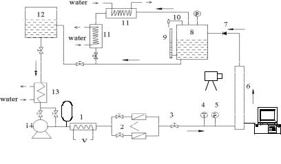
A schematic diagram of the experimental apparatus is given in Fig.1, which is adopted to study the boiling two-phase flow in tube-bundle channels. In the experiments, all measured
1. Preheater 2. Flowmeter 3. Control valve 4. Thermocouple 5. Pressure meter 6. Test section 7. Check valve 8. Seperator 9. Liquid-height meter 10. Relief valve 11. Condenser 12. Liquid tank 13. Cooler 14. Magnetopump 15. Manostat 16. High-speed camera 17. Data collector
Fig. 1. Schematic diagram of experimental apparatus (tube-bundle channel)
Investigation on Two-Phase Flow Characteristics in Nuclear Power Equipment |
187 |
data are recorded at the intervals of 10ms. The error in the pressure drop measurement is less than ±2%. The error in flow rate measurement is less than ±3%, and for temperature measurement is less than ±1%.
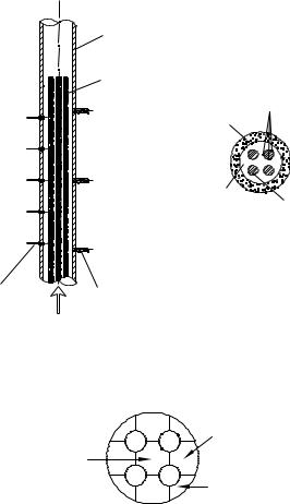
The test section of tube-bundle channel is composed of four straight electrical heaters and a thimble, which is shown in Fig. 2. The thimble is made of PMMA pipe for the purpose of flow visualization, of which the inner diameter is 35mm and the length is 2100mm. The dimension of the electrical heater is Φ8mm and 1500mm long; the gap between electrical heaters is 5mm; the width between electrical heater and thimble is 4.5mm. There are, along flow direction, three pressure sensors and five thermocouples. The length between pressure sensors is 200mm and that between thermocouples is 100mm.
|
Plexiglas pipe |
|
|
Electric heat tube |
|
|
|
Temperature |
5 |
P3 |
measuring point |
Plexiglas pipe |
|
|
4 |
|
|
3 |
P2 |
|
2 |
Test channel |
Electric |
|
heat tube |
|
1 |
P1 |
|
|
|
|
Thermocouples |
Pressure sensors |
|
|
|
Fig. 2. Structure of test section
A schematic diagram of sub-channels partition is shown in Fig. 3. There are 9 sub-channels in the present test section.
|
B |
A |
Side subchannel |
|
|
||
Central subchannel |
C |
|
|
|
|
|
Angle subchannel |
Fig. 3. Schematic diagram of sub-channels partition
188 |
Nuclear Power Plants |
2.2 Experiments of containment sump strainers
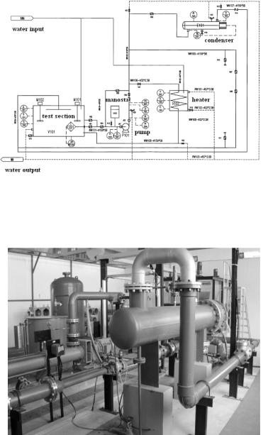
For the tests of containment sump strainers, the schematic diagram of the experimental apparatus is given in Fig.4.
Fig. 4. Schematic diagram of experimental apparatus for containment sump strainers
In order to monitor the tests, the test apparatus includes flow rate measurements, temperature measurements, and differential pressure measurement. High speed camera is adopted to perform the visual observation of the two-phase flow and the debris bed during the test and after the test. The photos of the test system are shown in Figs 5~7.
Fig. 5. Photograph 1 of the test system (containment sump strainers)
Investigation on Two-Phase Flow Characteristics in Nuclear Power Equipment |
189 |
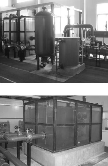
Fig. 6. Photograph 2 of the test system (containment sump strainers)
Fig. 7. Photograph 3 of the test system (containment sump strainers)
2.3 Experiments of control rod drive mechanism
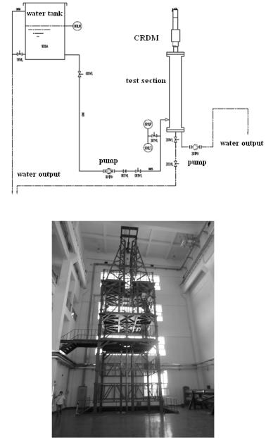
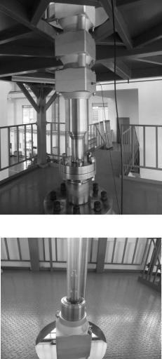
For the tests of control rod drive mechanism (CRDM) in nuclear power station, the schematic diagram of the experimental apparatus is given in Fig.8. And the photos of the test system are shown in Figs 9~11.
190 |
Nuclear Power Plants |
Fig. 8. Schematic Diagram of Experimental Apparatus (CRDM)
Fig. 9. Photograph 1 of the test system (CRDM)
There are four floors in the test bench, whose site area is 5m×5m and height is 25m. The photo of the test bench is shown in Fig. 9. The first floor is used to provide ground support for the test section and to settle the pump and pipeline. The second floor is adopted to upper support for
Investigation on Two-Phase Flow Characteristics in Nuclear Power Equipment |
191 |
the test section. The test section is joined with CRDM by J seal weld on the second floor. The photo of partial test section is shown in Fig. 10 and Fig. 11. CRDM is settled on the third floor. And the fourth floor is used to settle the crane and provide moving space for the driving rod.
Fig. 10. Photograph 2 of the test system (CRDM)
Fig. 11. Photograph 3 of the test system (CRDM)
3. Results and discussion
3.1 Test of tube-bundle channel
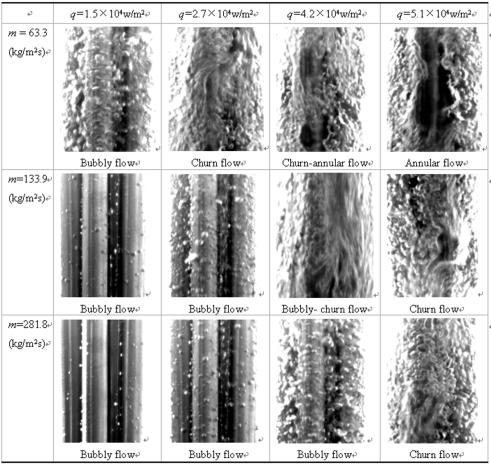
High-speed camera is adopted to carry out experiments of the two-phase boiling flow in the tube-bundle channel for different heat flux and different flow rate. Several representative pictures obtained are displayed in Fig.12.
192 |
Nuclear Power Plants |
Fig. 12. Flow patterns in a vertical tube-bundle channel
Fig. 12 shows that there are four main flow patterns, bubbly flow, bubbly-churn flow, churn flow and annular flow, which is different from flow patterns of two-phase boiling flow in a circular tube. Through the analyses, it is shown that there may be two reasons for these differences. Firstly, the geometric dimensions cause the different flow patterns. The tubebundle channel is divided into several sub-channels by the tubes, as shown in Fig. 12. And the inner tubes divide the large bubble and make disturbance on two-phase flow. Furthermore, flows in the sub-channels interact and enhance the complexity of two-phase flow in the tube-bundle channel. Secondly, the heating mode of boiling flow in the tubebundle channel and that in the circular tubes are different. When flowing in a circular tube, the fluid is surrounded and heated by the wall of the tube. On the other hand, in a tubebundle channel, the fluid surrounds the tube bundle, which acts as the heating source. Then, all of these might cause differences between flow patterns in vertical tube-bundle channels and that in vertical circular tubes (Hewitt & Roberts, 1969).
Investigation on Two-Phase Flow Characteristics in Nuclear Power Equipment |
193 |
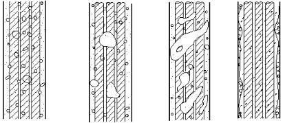
Two-phase boiling flow in tube-bundle channels exhibits several main flow patterns, bubbly flow, bubbly-churn flow, churn flow and annular flow, as shown in Fig. 13. There are differences from the results gained by Grant & Chisolm (1979) and Ma (1992). These differences might be caused by the different test conditions. The characteristics of flow patterns and transitions in the present experiments are analyzed as follows.
(a) Bubbly flow |
(b) Bubblychurn flow (c) Churn flow (d) Annular flow |
Fig. 13. Schematic diagram of flow pattern in a tube-bundle channel of upward flow
(1)Bubbly flow: In the experiments, bubbles begin to come into being in the liquid when the heat flux is small. The mainstream is liquid and discrete bubbles are dispersed in the mainstream, which indicates that bubbly flow in circular tubes is similar to that in the tubebundle channel, as shown in Fig. 13(a). With the sustaining heating, the dimension and the quantity of bubbles increase gradually along the flow direction, and discrete bubbles begin to aggregate to combine to be large bubbles. Confined by the narrow space in the tubebundle channel, large bubbles transfigure to be oval or crescent.
(2)Bubbly-churn flow: When the little discrete bubbles aggregate and combine to be large bubbles, the tubes agitate and divide these large bubbles. This makes there be no slug flow in the tube-bundle channel. And the flow pattern begins to be transformed from bubbly flow to churn flow.
(3)Churn flow: With the augmentation of heat flux, discrete bubbles continue to aggregate and combine and the aggregation bubbles become bigger in size. These aggregation bubbles present unstable state, on account of the agitation and division of the tubes. And the aggregation bubbles begin to burst into many little discrete bubbles with unequal geometric dimensions. Then, the flow pattern is transformed to churn flow.
When churn flow occurs in the tube-bundle channel, there might be many bubbles with unequal geometric dimensions. The liquid moves up and down in the channel and the twophase flow exhibits surge state.
(4) Annular flow: Heat flux continues increasing, and the dryness fraction in the channel increases too. When the vapor content is higher than that of churn flow, the liquid block is smashed and the vapor unites to be a continuous axle center in the core of the tube-bundle channel. The liquid film goes upward along the wall of PMMA pipe. Thus, annular flow occurs. The liquid film might be broken due to the effect of the vapor wave, as shown in Fig. 4 and Fig. 13 (d).
194 |
Nuclear Power Plants |
In the experiments, there is no mist flow due to the limit of the experiment condition, which is detected by Grant & Chisolm (1979).
There may be several differences between flow patterns and their transition in circular tubes and that in tube-bundle channels. Firstly, slug flow is one of the main flow patterns for two-phase flow in a circular tube. But the tube-bundle channels, the inner tubes divide the large bubbles and flows in the sub-channels interact, which makes bubbles can not aggregate and combine to be a slug. Thus there is a lack of slug flow in the tube-bundle channel and the flow pattern is transform directly from bubbly flow to churn flow. Secondly, churn flow, as the transition from slug flow to annular flow, exists transitory in circular tubes. Under some circumstances, there might be a lack of churn flow in circular tubes. But in the tube-bundle channel, churn flow presents itself as one of the main flow patterns. And churn flow exists in many experimental conditions and present a long time in the tube-bundle channel, as shown in Fig. 12.
With the same flow rate, there may be different flow patterns in the tube-bundle channel due to the different heat flux. For example, when the flow rate is 281.8 (kg/m2s), bubbly flow occurs in the tube-bundle channel where the heat flux is comparatively small. But the amount of bubbles begin to increase with the enhanced heat flux. And the flow pattern changes from bubbly flow to churn flow when the heat flux is equal to 5.1×10⁴ (w/m2). This difference in flow patterns will be more obvious along with the decrease of the flow rate, which is shown in Fig. 12. When the flow rate is 133.9 (kg/m2s), there will appear three flow patterns, which are bubbly flow, bubbly-churn flow and churn flow, under different heat flux in the tube-bundle channel. And when the flow rate is getting smaller, the flow patterns with differnet heat flux will be differentiated more distinctly. As shown in Fig. 12, there appear four different flow patterns, which are bubbly flow, churn flow, churn-annular flow and annular flow, when the flow rate is equal to 63.3 (kg/m2s). From above all, it is shown that heat flux will affect the flow pattern more remarkably under the small flow rate condition.
Furthermore, it is found that there may be two different flow patterns in the same crosssection when the experiments run. The flow pattern transitions exhibit unsynchronized in different sub-channels. This unsynchronized phenomenon is caused by the different geometric dimensions, different heat flux and different quantity of discrete bubbles generated in different sub-channels. It was found the same phenomenon in a tube-bundle channel by adopting microprobe to detect the flow pattern transitions (Bergles 1981).
The flow pattern map obtained in the experiments is shown in Fig. 14. Comparisons are made with the results gained by Hewitt & Roberts (1969), which is figured by dashed line. Two-phase flow patterns and their transition in vertical circular tubes were experimentally studied by Hewitt & Roberts. The mass flow rate in the present experiments is less than that of Hewitt & Roberts owing to the experimental condition limits. In Fig. 6, the abscissa ' j2f and the ordinate " jg2 are calculated by (Hewitt & Roberts, 1969),
' j 2f |
G2 (1 x)2 |
(1) |
||
|
||||
|
|
|
' |
|
" jg2 |
|
G 2 x2 |
(2) |
|
|
|
|
" |
|