

NUCLEAR POWER PLANTS
.pdf
|
Cross-Flow-Induced-Vibrations in Heat Exchanger Tube Bundles: A Review |
95 |
|
|
|
|
|
|
|
|
Formula/ Procedure |
Conditions |
|
|
|
|
|
|
|
|
Analytical/experimental |
Straight tubes single/multiple spans with |
|
|
|
damped/ fixed boundaries, Experimentation on |
|
||
|
(Khushnood et al., 2000) |
|
||
|
refinery research exchanger (in-service) |
|
|
|
|
|
|
|
|
|
|
|
|
|
|
|
Tubes were not fully straightened. |
|
|
|
Plucking and transient decay |
(Slight residual wiggleness) |
|
|
|
Wind tunnel determination of fluid-elastic |
|
|
|
|
(Simpson & Hartlen, 1974) |
|
|
|
|
thresholds |
|
|
|
|
|
|
|
|
|
|
Tubes were found sensitive to temperature |
|
|
|
|
|
|
|
Table 5. Tube natural frequencies (MacDuff et al., 1957, Kissel, 1977)
4. Dynamic parameters
Added mass and damping are known to be dependent on fluid properties (in particular, fluid density and viscosity) as well as functions of component geometry and adjacent boundaries, whether rigid or elastic. Nuclear reactor components are typically immersed in a liquid coolant and are often closely spaced (Wambsganss, et al., 1974).
4.1 Added mass
(TEMA, 7th Edition, 1988) defines hydrodynamic mass as an effect which increases the apparent weight of the vibrating body due to the displacement of the shell-side flow resulting from motion of vibrating tubes, the proximity of other tubes within the bundles and relative location of shell-wall. The so-called "virtual mass" for a tube is composed of the mass of the tube, mass of the fluid contained in the tube and the inertia M imposed by the surrounding fluid. This hydrodynamic mass M is a function of the geometry, the density of the fluid, and the size of the tube. In an ideal fluid, it is proportional to the fluid density and to the volume of the tube (Moretti & Lowry, 1976), and hence may be expressed, per unit length as:
|
M' |
Cm r2 |
(18) |
|
L |
||
|
|
|
|
where L is the tube length, r the radius of the tube and |
is the mass per unit volume of |
||
the surrounding fluid, Cm is called the inertia coefficient which is a function of the geometry, and is discussed by Lamb (Lamb, 1932, 1945). If the moving tube is not infinitely long, the flow is three-dimensional and leads to smaller values of Cm (Moretti & Lowry, 1976). For a vibrating tube in a fluid region bounded by a circular cylinder, Stokes (Endres & Moller, 2009) has determined hydrodynamic mass per unit length as given by:
mh Cmma |
(19) |
96 |
|
|
|
|
|
Nuclear Power Plants |
|
where |
C |
|
R2 |
r2 |
, R is the outer radius of annulus and, |
m r2 |
, where is fluid |
|
|
||||||
|
m |
|
R2 |
r2 |
|
a |
|
|
|
|
|
|
|
||
density, and r |
is the tube radius. |
|
|
||||
(Wambsganss, et al., 1974) have published a study on the effect of viscosity on Cm . Hydrodynamic mass M for a tube submerged in water was determined by measuring its natural frequency, fa , in air and, fw , in water. Neglecting the density of air compared to water, the following equation may be obtained from beam equation (Moretti & Lowry, 1976).
M |
|
|
fa |
|
2 |
|
|
|
|
|
(20) |
||||
L |
|
f |
|
|
1 |
||
|
|
|
|
w |
|
|
|
where is the tube mass per unit length. The inertia coefficient, Cm , can be obtained from Equation 18. Figure 13 gives the results showing the variation of Cm with pitch-to-diameter ratios (Wambsganss, et al., 1974).
Cm
P/D ratio
Fig. 13. Experimental Cm -values in tube bundles (Wambsganss et al., 1974, Moretti et al., 1976).
4.2 Damping
System damping has a strong influence on the amplitude of vibration. Damping depends upon the mechanical properties of the tube material, the geometry of intermediate supports and the physical properties of the shell-side fluid. Tight tube-to-baffle clearances and thick baffles increase damping, as does very viscous shell-side fluid (Chenoweth, 1993). (Coit et al., 1974) measured log decrements for copper-nickel finned tubes of 0.032 in still air. The range of most of the values probably lies between 0.01 and 0.17 for tubes in heat exchangers (Chenoweth, 1993). From (Wambsganss, et al., 1974), damping can be readily obtained from the transfer function or frequency response curve as

Cross-Flow-Induced-Vibrations in Heat Exchanger Tube Bundles: A Review |
97 |
|
|
|
|
1 |
|
fn |
(21) |
|
|
|
N 2 1 fn |
||||
|
|
2 |
|
||||
with fn fN (1) fN |
(2) , |
|
|
|
|
|
|
where fn is the resonant frequency and |
fN (1) |
and fN (2) are the frequencies at which the |
|||||
response is a factor |
1 |
of resonant response. |
|
|
|
||
Nth |
|
|
|
||||
|
|
|
|
|
|
|
|
(Lowery & Moretti, 1975), have concluded that damping is almost entirely a function of the supports. More complex support conditions (non-ideal end supports or intermediate supports with a slight amount of clearance) lead to values around 0.04. From analytical point of view, (Jones, 1970) has remarked that in most cases, the addition of damping to the beam equation re-couples its modes. Only a beam, which has, as its damping function, a restricted class of functions can be uncoupled. (Chen et al., 1994) have found the fluid damping coefficients from measured motion-dependent fluid forces. (Pettigrew et al., 1986, 1991) outlines the energy dissipation mechanisms that contribute to tube damping as given in Table 6:
Type of damping |
Sources |
|
|
Structural |
Internal to tube material |
|
|
Viscous |
Between fluid forces and forces transferred to fluid |
Flow-dependent |
Varies with flow regime. |
|
|
Squeeze film |
Between tube and fluid as tube approaches support |
|
|
Friction |
Coulomb damping at support |
Tube support |
Internal to support material |
|
|
Two-phase |
Due to liquid gas mixture |
|
|
Thermal damping |
Due to thermal load |
Table 6. Energy dissipation mechanisms (Pettigrew et al., 1986, 1991)
4.3 Parameters influencing damping
(Pettigrew et al., 1986) further outlines the parameters that influence damping as given below:
The Type of tube motion. There are two principal types of tube motion at the supports, rocking motion and lateral motion. Damping due to rocking is likely to be less. Rocking motion is pre-dominant in lower modes. Dynamic interaction between tube and supports may be categorized in three main types, namely: sliding, impacting, and scuffing, which is impacting at an angle followed by sliding:
Effect of number of supports. The trend available in damping data referenced in (Pettigrew et al., 1986), when normalized give
98 |
Nuclear Power Plants |
n N / (N 1) |
(22) |
where n is the normalized damping ratio, N is the |
number of spans, and is the |
damping ratio. |
|
Effect of tube Frequency. Frequency does not appear to be significant parameter (Pettigrew et al., 1986).
Effect of vibration amplitude. There is no conclusive trend of damping as a function of amplitude. Very often, amplitude is not given is damping measurements (Pettigrew et al., 1986).
Effect of diameter or mass. Large and massive tubes should experience large friction forces and the energy dissipated should be large. However, the potential energy in the tube would also be proportionally large in more massive tubes. Thus, the damping ratio, which is related to the ratio of energy dissipated per cycle to the potential energy in the tube should be independent of tube size or mass (Pettigrew et al., 1986).
Effect of side loads. In real exchangers, side loads are possible due to misalignment of tubesupports or due to fluid drag forces. Side loads may increase or reduce damping. Small side loads may prevent impacting, and thus reduce damping, whereas large side loads may increase damping by increasing friction (Pettigrew et al., 1986).
Effect of higher modes. Damping appear to decrease with mode order, for mode order higher than the number of spans, since these higher modes involve relatively less interaction between tube and tube-support (Pettigrew et al., 1986).
Effect of tube support thickness. Referenced data in (Pettigrew et al., 1986) clearly indicates that support thickness is a dominant parameter. Damping is roughly proportional to support thickness. (Pettigrew et al., 1986) corrected the damping data line for support width less than 12.7mm such that
12.7 |
|
|
||
nc n |
|
|
(23) |
|
L |
||||
|
|
|
||
where L is support thickness in mm and nc is the corrected normalized damping ratio.
Effect of clearance. For the normal range of tube-to-support diametral clearances (0.40mm- 0.80mm), there is no conclusive trend in the damping data reviewed (Pettigrew et al., 1986).
Design Recommendations (Pettigrew et al., 1986, 1991, Taylor et al., 1998)
Friction damping ratio in a multi-span tube (percentage)
(For liquid) F 0.5 |
|
N 1 |
L |
1/ 2 |
(24) |
||||||||
|
|
|
|
|
|
|
|
|
|||||
|
|
|
|
||||||||||
|
|
|
N |
|
|
lm |
|
|
|||||
(For gas) F 5.0 |
N 1 |
|
L 1/ 2 |
(25) |
|||||||||
|
|
|
|
|
|
|
|
|
|
||||
|
|
|
|
|
|
|
|||||||
|
|
|
|
N |
lm |
|
|
||||||

Cross-Flow-Induced-Vibrations in Heat Exchanger Tube Bundles: A Review |
99 |
where N is the number of tube spans, L is the support thickness, |
lm is the characteristic |
span length usually taken as average of three longest spans. |
|
Viscous damping ratio
Rogers simplified version of Chens' cylinder viscous damping ratio (percentage) of a tube in liquid.
F |
100 D2 |
2 |
1/ 2 |
|
1 (D / D )3 |
|
|
|||
|
|
|
|
|
|
|
e |
|
(26) |
|
8 |
|
fD2 |
(1 (D / D )2 )2 |
|||||||
|
|
m |
|
|
|
|
||||
|
|
|
|
|
|
|
e |
|
||
|
|
|
|
|
|
|
||||
where is the fluid density, m is the mass per unit length of tube (interior fluid and hydrodynamic mass), De is the equivalent diameter to model confinement due to
surrounding tubes, D is the tube diameter, |
|
f is the frequency of tube vibration and is |
|||||||||||
the fluid kinematic viscosity. The term S |
fD2 |
is the Stoke number. |
|
|
|||||||||
|
2 |
|
|
||||||||||
|
|
|
|
|
|
|
|
|
|
|
|
||
Squeeze film damping ratio |
|
|
|
|
|
|
|
|
|
|
|
|
|
(For multi-span tube) |
|
|
N 1 1460 |
|
D2 |
L |
1/ 2 |
(27) |
|||||
|
|
|
|
|
|
|
|
|
|
|
|||
|
|
|
|
|
|||||||||
|
|
|
|
f |
|
m |
|
|
|
||||
|
|
|
N |
|
lm |
|
|||||||
Support damping
(Pettigrew, et al., 1991) has developed a semi-empirical expression to formulate support damping, using Mulcahys' theory (Mulcahy, 1980).
|
|
|
N 1 |
|
2200 |
|
D2 |
|
L 0.6 |
(28) |
||||
s |
|
|
|
|
|
|
|
|
|
|
|
|||
N |
f |
m |
l |
|
||||||||||
|
|
|
|
m |
|
|||||||||
|
|
|
|
|
|
|
|
|
|
|
|
|
||
(TEMA, 6th Edition, 1978, TEMA, 7th Edition, 1988)
According to TEMA standards, is equal to greater of 1 , and 2
(For shell-side liquids)
|
|
1 |
|
3.41do |
|
|
|
(29) |
|||
|
|
Wo fn |
|
|
|||||||
|
|
|
|
|
|
|
|||||
2 |
|
0.012d |
o |
|
|
v 1/ 2 |
|
||||
|
|
|
|
o |
|
|
(30) |
||||
|
Wo |
|
fn |
||||||||
|
|
|
|
|
|
|
|||||
where v is the shell fluid velocity, do is the outside tube diameter, o is the density of shellside fluid, fn is the fundamental frequency of tube span, and Wo is the effective tube weight.
(For shell-side vapors)
100 |
|
|
|
|
|
|
Nuclear Power Plants |
|
|
0.314 |
N 1 |
tb 1/ 2 |
(31) |
||||
|
|
|
|
|
||||
N |
|
l |
|
|||||
|
|
|
||||||
where N is the number of spans, tb is the baffle or support plate thickness, and l is the tube
unsupported span. A review of two-phase flow damping is presented by (Khushnood et al., 2003).
5. Damage numbers for collision and baffle damage (Chenoweth, 1976, Shin et al., 1975, Brothman et al., 1974)
Two types of vibration damage are prevalent in cross-flow regions of steam generators (Shin & Wambsganss, 1975).
Tube-to-baffle impact.
Tube-to-tube collision.
(Thorngren, 1970) deduced "damage numbers" for the two types of damage, based on the assumption that tube is supported by baffles and deflected by a uniformly distributed lift force. These damage numbers are given by following equations:
|
(Baffle damage number) NBD |
|
d V 2l2 |
|
|
|
|||||
|
1Sm gc AmBt |
|
|
||||||||
|
|
|
|
|
|
|
|
||||
|
(Collision damage number) NCD |
|
|
0.625 d V 2l4 |
|
|
|||||
|
4 g |
A |
(d 2 d 2 )C E |
||||||||
|
|
|
|
|
|||||||
|
|
|
|
|
1 |
|
c m |
i |
T |
||
where |
|
|
|
|
|
|
|
|
|
|
|
NBD 1 for safe design. |
|
|
NCD 1 for safe design. |
|
|
||||||
CT |
= Maximum gap between tubes. |
|
d = Tube outer diameter. |
||||||||
di |
= Tube inner diameter. |
1 |
= Tube-to-baffle-hole clearance factor. |
||||||||
E = Modulus of elasticity. |
gc |
= Gravitational constant. |
|
|
|||||||
Bt |
= Baffle thickness. |
|
|
= Mass density of shell side fluid. |
|||||||
l = Length of tube between supports. |
|
V = Free stream velocity. |
|
|
|||||||
A |
= Tube cross-sectional area |
(d 2 |
d 2 ) |
and |
|
|
|
|
|
|
|
m |
|
|
i |
|
|
|
|
|
|
|
|
|
|
4 |
|
|
|
|
|
|
|
|
|
Sm = Maximum allowable fatigue stress [ASME Pressure Vessel code Sec. III].
(32)
(33)
Collision damage is usually predicted together with baffle damage, whereas the latter can be predicted without collision damage being indicated, i.e., baffle damage is important factor when appraising design (Erskine et al., 1973). (Burgreen et al., 1958) were the first to conduct an experiment to investigate vibration of tube for fluid flowing parallel to tube axis. (Quinn, 1962) and (Paidoussis, 1965) have developed analytical and empirical expressions respectively for peak amplitude. Paidoussis give the following expression:

Cross-Flow-Induced-Vibrations in Heat Exchanger Tube Bundles: A Review |
101 |
||||||||||
|
|
|
4 |
U1.6 1.8R0.25 |
d |
h |
0.4 |
2/3 (5 10 4 K p ) |
|
||
|
|
|
|
e |
|
|
|
|
(34) |
||
|
|
|
|
2 |
|
|
|
||||
|
|
d |
1 |
I U |
d |
I 4 |
|
||||
|
|
|
|
|
|
|
|||||
where |
|
|
|
|
|
|
|
|
|
|
|
K p |
= |
Flow condition constant |
|
|
|
|
|
|
|||
= Maximum vibration amplitude at mid-span
d |
= |
Outer diameter of tube |
1 |
= |
First mode beam eigen value of the tube |
U |
= |
Dimensionless flow velocity |
d
= Tube length
dh |
= |
Hydraulic diameter |
Re |
= |
Reynolds number |
I |
= |
Moment of inertia and |
= Added mass fraction
Later on a number of expressions for peak and RMS amplitudes have been developed (Shin et al., 1975, Blevins, 1977).
6. Wear work-rates
In fretting wear, work-rate is defined as the rate of energy dissipation when a tube is in contact with its support. Energy is being dissipated through friction as the tube moves around in contact with its supports. A force (the contact force between tube and support) multiplied by a displacement (as the tube slides) results in work or dissipated energy required to move the tube (Taylor et al., 1998, Au-Yang, 1998). Normal work-rate Wn for different tube and tube support plate material combinations and different geometries (AuYang, 1998) is defined.
|
T |
|
|
|
|
|
W |
1 |
T |
F |
|
dS |
(35) |
|
|
|||||
n |
|
|
n |
|
|
|
|
|
0 |
|
|
|
|
where T is the total time, Fn is the normal contact force, and S is the sliding distance.
(Au-Yang, 1998) has assessed the cumulative tube wall wear after 5, 10, and 15, effective full power years of operation of a typical commercial nuclear steam generator, using different wear models.
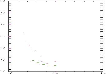
The EPRI data reproduced from (Hofmann & Schettlet, 1989) in Figure 14 shows the wear volume against normal work-rate for the combination of Inconel 600 tube (discrepancy as plot shows J 600 whereas text indicates Inconel 600) and carbon tube support plate, a condition that applies to many commercial nuclear steam generators (Hofmann & Schettlet, 1989). Figure 15 shows the tube wall thickness loss against volumetric wear for different support conditions (Hofmann & Schettlet, 1989).
102 |
Nuclear Power Plants |
V olum e w ear rate at the tube (steady state data)
|
|
|
|
|
|
|
|
|
|
|
|
"w ork rate"=590 |
|
|
|
||||||||
|
|
|
|
|
|
|
|
|
|
|
|
volum e loss=0.6 |
|
g |
|
||||||||
|
|
|
|
|
|
|
|
|
|
|
|
|
|
|
|
|
|
|
|
|
|
in |
|
0.3 |
|
|
|
|
|
|
|
|
|
|
|
|
|
|
|
|
|
|
|
|
|
id |
|
|
|
|
|
|
|
|
|
|
|
|
|
|
|
|
|
|
|
|
|
|
l |
|
|
|
|
|
|
|
|
|
|
|
|
|
|
|
|
|
|
|
|
|
|
|
g |
s |
|
|
|
|
|
|
|
|
|
|
|
|
|
|
|
|
|
|
|
|
|
|
|
|
|
3 |
|
|
|
|
|
|
|
|
|
|
|
|
|
|
|
|
|
|
|
in |
|
|
|
|
|
|
|
|
|
"w ork rates"=440 |
|
|
|
|
|
|
|
t |
|
|
|
||||||
m m /d |
|
|
|
|
|
|
|
|
|
|
|
|
la |
|
|
|
|||||||
|
|
|
|
|
|
|
|
|
|
|
|
|
|
|
|
|
il |
|
|
|
|
||
|
|
|
|
|
|
|
volum e loss=0.46 |
|
|
|
|
c |
|
|
|
|
|
||||||
|
|
|
|
|
|
|
|
|
|
s |
|
|
|
|
|
|
|||||||
|
|
|
|
|
|
|
|
|
|
|
|
|
|
|
e |
o |
|
|
|
|
|
|
|
|
|
|
|
|
|
|
|
|
|
|
|
|
|
|
|
|
|
|
|
|
|
|
|
|
|
|
|
|
|
|
|
|
|
|
|
|
|
r |
|
|
|
|
|
|
|
|
|
|
ng |
|
|
|
|
|
|
|
|
|
|
|
|
u |
|
|
|
|
|
|
|
|
|
0.2 |
|
|
|
|
|
|
|
|
|
|
|
|
P |
|
|
|
|
|
|
|
|
|
|
|
|
|
|
|
|
|
|
|
|
|
|
J 600 (tube) against |
|||||||||||
i |
|
|
|
|
|
|
|
|
|
|
|
|
|||||||||||
|
t |
|
|
|
|
|
|
|
|
|
|
|
|
|
|
|
|
|
|
|
|
|
|
|
c |
|
|
|
|
|
|
|
|
|
|
|
|
405 S S (drilled hole) |
|||||||||
|
pa |
|
|
|
|
|
|
|
|
|
|
|
|
||||||||||
|
|
|
|
|
|
|
|
|
|
|
|
|
|
|
|
|
|
|
|
|
|
|
|
|
m |
|
|
|
|
|
|
|
|
|
|
|
|
|
|
|
|
|
|
|
|
|
|
|
i |
|
|
|
|
|
g |
|
|
|
|
|
|
|
|
|
|
|
|
|
|
|
|
|
e |
|
|
|
|
|
|
|
|
|
|
|
|
|
|
|
|
|
|
|
|
||
|
|
|
|
|
|
in |
|
|
|
|
|
|
|
|
|
|
|
|
|
|
|
|
|
|
ur |
|
|
|
|
id |
|
|
|
|
|
|
|
|
|
|
|
|
|
|
|
|
|
|
|
|
|
|
l |
|
|
|
g |
J 600 (tube) against |
|||||||||||||
|
P |
|
|
|
+ |
s |
|
|
|
||||||||||||||
|
|
|
|
t |
|
|
|
|
in |
|
|
carbon steel(drilled hole) |
|||||||||||
|
|
|
|
|
|
|
|
|
t |
|
|
||||||||||||
0.1 |
|
|
c |
|
|
|
|
|
c |
|
|
|
|
|
|
|
|
|
|
|
|
|
|
|
|
|
|
|
|
|
a |
|
|
|
|
|
|
|
|
|
|
|
|
|
|||
|
a |
|
|
|
|
|
p |
|
|
|
|
|
|
|
|
|
|
|
|
|
|||
|
Im |
p |
|
|
|
|
|
im |
|
"w ork rate"=800 |
|
|
|
|
|
|
|||||||
|
|
|
|
|
|
e |
|
|
|
|
|
|
|
|
|||||||||
|
|
|
|
|
|
|
r |
|
|
|
|
|
|
|
|
|
|
|
|
|
|
|
|
|
|
|
|
|
|
u |
|
|
|
|
volum e loss+0.097 |
|
|
|
|||||||||
|
|
|
|
|
|
P |
|
|
|
|
|
|
|
|
|||||||||
|
|
|
|
|
|
|
|
|
|
g |
|
|
|
|
|
|
|
|
|
|
|
|
g |
|
|
|
|
|
|
|
|
|
din |
|
|
|
|
|
|
|
|
|
|
|
|
||
|
|
|
|
|
|
|
+ |
sli |
|
|
|
|
|
|
|
|
|
|
|
|
idin |
||
|
|
|
|
|
ct |
|
|
|
|
|
|
|
|
|
|
|
tin |
g sl |
|
||||
|
|
|
pa |
|
|
|
|
|
|
|
|
|
cilla |
|
|
|
|
||||||
|
Im |
|
|
|
|
|
|
|
|
re |
os |
|
|
|
|
|
|
|
|
||||
0 |
|
|
|
|
|
|
|
|
|
|
|
Pu |
|
|
|
|
|
|
|
|
|
|
|
|
|
|
|
|
|
|
|
|
|
|
|
|
|
|
|
|
|
|
|
|
|
|
|
|
0 |
|
|
|
100 |
|
|
|
|
200 |
|
|
|
|
|
|
|
N m m /s |
|
||||
|
|
|
|
|
|
|
|
|
|
|
|
|
|
|
|
|
|
|
|
|
|||
w ork rate
Fig. 14. Volumetric wear rate versus normal work-rate for different material combinations (Hofmann & Schettlet, 1989).
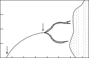
reduction[mm] |
T yp e o f m o tio n :p u re im p a ctin g |
|
|
M a te ria ls: th e sa m e fo r tu b e a n d su p p o rt |
|||
0 .5 |
|
A V B |
|
|
|
||
0 .4 |
|
|
|
wall thickness |
|
|
|
0 .3 |
|
|
|
0 .2 |
|
e g g cra te |
|
tube |
|
||
|
|
||
|
|
|
|
|
0 .1 |
|
b o re h o le |
|
0 |
|
|
|
5 |
1 0 |
1 5 |
|
|
tu b e w e a r vo lu m e [m m3] |
|
Fig. 15. Tube wall thickness loss versus volumetric wear for different support conditions, from Hofmann and Schettler (Hofmann & Schettlet, 1989).
Cross-Flow-Induced-Vibrations in Heat Exchanger Tube Bundles: A Review |
103 |
(Payen et al., 1995) have carried predictive analysis of loosely supported tubes vibration induced by cross-flow turbulence for non-linear computations of tube dynamics. They have analyzed the gap effect and have concluded that wear work-rate decreases when the gap value increase at low velocities. (Peterka, 1995) has carried out numerical simulation of the tubes impact motion with generally assumed oblique impacts. (Charpentier and Payen, 2000) have carried out prediction of wear work-rate and thickness loss in tube bundles under cross-flow by a probabilistic approach. They have used Archard's Law and wear correlation depending on the contact geometry, and have concluded that most sensitive parameters that affect the wear work-rate are the coefficient of friction, the radial gap and the spectral level of turbulent forces.
(Paidoussis & Li, 1992) and (Chen et al., 1995) have studied the chaotic dynamics of heat exchanger tubes impacting on the generally loose baffle plates, using an analytical model that involves delay differential equations. They have developed a Lyapunov exponent technique for delay differential equations and have shown that chaotic motions do occur. They have performed analysis by finding periodic solutions and determining their stability and bifurcations with the Poincare map technique. Hopf bifurcation is defined as the loss of stable equilibrium and onset of amplified oscillation (Paidoussis & Li, 1992).
|
0.08 |
|
|
|
Displacement |
|
|
UD |
|
0.04 |
|
|
|
|
|
|
|
|
|
|
UH |
|
|
|
|
|
|
|
UCH |
|
0.00 |
3.0 |
4.0 |
5.0 |
|
2.0 |
Fluid Velocity
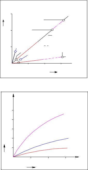
Fig. 16. The bifurcation diagram (Paidoussis & Li, 1992, Chen et al., 1995)
A typical bifurcation diagram for the symmetric cubical model with P / D 1.5 , is given in Figure 16 showing dimensionless mid-point displacement amplitude in terms of dimensionless fluid velocity. Where UH denotes critical U for Hopf bifurcation, UD , is the first post Hopf bifurcation, and UCH denotes the onset of chaos. Total wear work rates against pitch velocity and mass flux have been given by (Taylor et al., 1995) and (Khushnood et al., 2003).
104 |
Nuclear Power Plants |
||
|
|
|
|
|
Researchers |
Salient fretting - wear features |
|
|
|
|
|
|
|
The evaluation of turbulence excitation is very challenging. |
|
|
|
Identification of key wear factors that can be correlated to |
|
|
|
assembly operating conditions. |
|
|
(Rubiolo & |
Functional dependence of wear damage against identified factors. |
|
|
Young, 2009) |
Grid cell clearance size and turbulence forces as key risk factors for |
|
|
|
PWR fuel assemblies. |
|
|
|
Grid misalignment and cell tilts are less important. |
|
|
|
Minimization of wear risk through modification in core loading. |
|
|
|
Fretting wear in helical coil tubes steam generator. |
|
|
(Jong & Jung, |
Thermal-Hydraulic prediction through FEM. |
|
|
Emphasis on the effects of number of supports, coil diameter and |
|
|
|
2008) |
|
|
|
helix pitch on free vibration modes. |
|
|
|
|
|
|
|
|
Design guidelines for designers and regulatory reviewers. |
|
|
|
Investigation of fretting wear of Zr-2.5% Nb alloy. |
|
|
|
Experimental setup includes special design fretting wear |
|
|
(Attia, 2006a) |
tribometers. |
|
|
Fretting wear is initially dominated by adhesion and abrasion and |
|
|
|
|
|
|
|
|
then delamination and surface fatigue. |
|
|
|
Volumetric wear loss decreased with number of cycles. |
|
|
|
Fitness for service and life management against fretting fatigue. |
|
|
|
Examples of fretting problems encountered in nuclear power |
|
|
|
plants. |
|
|
(Attia, 2006b) |
Methodology to determine root cause. |
|
|
Non-linearity of the problem and risk management. |
|
|
|
|
|
|
|
|
Critical role of validation experimentally (long term) under |
|
|
|
realistic conditions and to qualify in-situ measurements of fretting |
|
|
|
damage non-destructive testing. |
|
|
|
Probabilistic method of fretting wears predictions in fuel rods. |
|
|
|
Non-linear vibration model VITRAN (Vibration Transient |
|
|
|
Analysis). |
|
|
(Rubiolo, 2006) |
Numerical calculations of grid work and wear rates. |
|
|
|
Monte carlo method applied for transient simulations (due to large |
|
|
|
variability of fuel assemble parameters). |
|
|
|
Design preference of fuel rods. |
|
|
|
A way toward efficient of restraining wear. |
|
|
|
Increase in contact area through two different contours of spacer |
|
|
|
grid spacing. |
|
|
(Kim et al., |
Consideration of contact forces, slip displacement and wear scars |
|
|
on rods to explore mechanical damage phenomenon. |
|
|
|
2006) |
|
|
|
It concludes that the contact shape affects the feature and behavior |
|
|
|
|
|
|
|
|
of length, width and volumetric shape of wear. |
|
|
|
A new parameter “equivalent depth” is introduced to represent |
|
|
|
wear severity. |
|
Table 7. Salient features of some recent researches on fretting wear Damage in Tube Bundles.