

NUCLEAR POWER PLANTS
.pdfInvestigation on Two-Phase Flow Characteristics in Nuclear Power Equipment |
195 |
It is shown in Fig. 14 that there are great differences between flow pattern transitions in a tube-bundle channel and that in a circular tube. The generation regions of bubbly flow and churn flow in a tube-bundle channel move left in Fig. 14, compared with the region in a circular tube. And it is shown that the regions of bubbly flow and churn flow are larger in a tube-bundle channel, which is caused by that the inner tubes have effects of disturbance and division on the bubbles and these effects make it impossible for discrete bubbles to converge and unite to be a slug. In addition, on account of being heated by the inner tubes, the fluid generates bubbles in the core of the channel, which makes the probability increase for bubbles to converge and unit to be a continuous axle center in the core of the tube-bundle channel, and then the flow pattern transform to annular flow in a tube-bundle channel is earlier than that in a circular tube.
|
104 |
|
|
|
|
|
|
|
|
|
|
|
103 |
|
|
|
|
|
|
|
|
|
|
|
|
|
|
|
|
|
|
Annular Flow |
|
|
|
|
102 |
|
|
|
|
2 g |
|
|
|
|
|
j |
□□□□□ |
|
|
||
ρ" |
|
|
|||
|
□□□□□ |
|
|
||
|
101 |
|
|
||
|
□□□□□ |
|
|
||
|
|
□□□□ Bubble Flow |
|
||
|
|
|
□□□ |
|
|
|
|
|
|
|
|
|
|
|
□□ |
|
|
|
100 |
|
|
|
|
|
|
Churn Flow |
|
|
|
|
10-1 |
102 |
103 |
104 |
105 |
|
101 |
||||
|
|
|
ρ' j 2 |
|
|
|
|
|
f |
|
|
Fig. 14. Flow pattern map of two-phase boiling flow in a tube-bundle channel of upward flow
3.2 Test of containment sump strainer
In the tests of containment sump strainer, the solid debris such as fiber and particulate is put into the test system. And then the liquid-solid two-phase flow comes into being. Three main tests are carried out to measure pressure drop of the debris bed, which are clean screen test, thin bed test and full fiber/particulate load test. If there is vortex on the water surface, air may be inhaled into the pump, and then cavitation erosion would appear. So the vortex formation is carefully observed in these tests.
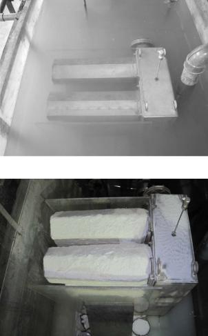
Clean screen test is performed without debris, which is shown in Fig. 15.
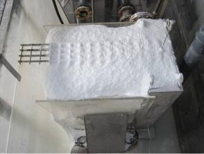
The thin bed test is conducted for the purpose of determining the amount of fiber fines which are necessary to completely cover the strainer. When the full coverage of the strainer screen is visually observed, the strainer screen should be photographed. The post-test photograph of thin bed test is shown in Fig. 16. It can be seen that the strainer is completely covered by fibrous debris and the thin bed is formed.
196 |
Nuclear Power Plants |
Fig. 15. Photograph of clean screen test
Fig. 16. Post-test photograph of thin bed test
Full fiber/particulate load test is performed to determine the head loss associated with the maximum fibrous and particulate debris load. In this test, full debris load is put into the test tank and the strainer is covered by more debris than that in the thin bed test. And the posttest photograph of full fiber/particulate load test is shown in Fig. 17.
As the safety nuclear apparatus, the containment sump strainers filter the debris out of the recycling water and provide the filtered water for the emergency core cooling system (ECCS) and the containment spray system (CSS). In order to keep the normal operation of ECSS pump and CSS pump, the containment sump strainers must guarantee sufficient NPSH (net positive suction head). Then the pressure loss due to the accident-generated debris accumulated on the sump screens should be one of the most important parameters of he containment sump strainers. And liquid-solid two-phase flow will appear when the accident-generated debris is flushed into the recycling water. NPSH of ECCS pump and CSS
Investigation on Two-Phase Flow Characteristics in Nuclear Power Equipment |
197 |
pump will be directly affected by this two-phase flow, of which the characteristics are important and significant for researchers to investigate.
Fig. 17. Post-test photograph of full fiber/particulate load test
In the tests of containment sump strainer, the solid debris such as fiber and particulate is put into the liquid. And the liquid-solid two-phase flow comes into being, which is different from the flow patterns in tube-bundle channels. The liquid-solid two-phase flow and the debris bed covering on the containment sump strainer are carefully observed and recorded in the tests.
In the recycling course, the ECCS and CSS systems would adopt the water in the containment as pump source when the water in PTR001BA was used up. The debris generated by LOCA or HELB would be transported to the containment ground floor with the elevation of -3.5m. And a fraction of debris would accumulate on the sump screen which could induce pressure loss and might lead to the pump failure of ECCS and CSS systems. The debris transportation fraction to the sump strainers is analyzed by numerical simulation.
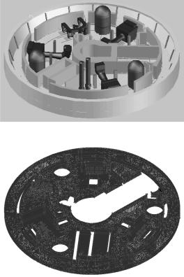
The authors take Daya Bay PWR for example to establish a 3-D computational model, with the purpose of studying the debris types and contents transported to the sump strainers. According to the actual dimension of the containment sump strainer in Daya Bay nuclear power station, a 3-D CAD model is established, as shown in Fig. 18. The altitude of the CAD model is ranging from -3.5m to 0m.
Then this CAD model is imported into Gambit, and the computational grid can be plotted. The cooper mode is adopted in defining the computational grid. In the complex locality and the key position, the computational grid is refined to resolve the important features. For the main part of the model, 5×5×5cm mesh spacing is induced in x-y-z directions. And the total cell amount in the model is 7,166,332, which is shown in Fig. 19.
In CFD model, the water temperature in the containment is set as 120 and the pressure is 1.99bar. In this circumstance, the water is sub-cooled and the water density is 943kg/m3, and the viscosity is 2.32×10⁻⁴ Pa·s.
According to the mass conservation principle and momentum conservation principle, continuity equation and momentum equation are established.
198 |
Nuclear Power Plants |
Fig. 18. 3-D CAD model of containment
Fig. 19. Computational grid of containment
|
|
|
|
|
|
ui |
0 |
|
|
|
|
|
|||
|
|
|
t |
xi |
|
|
|
|
|
||||||
|
ui |
|
uiuj |
p |
|
|
|
|
ui |
|
|
||||
|
|
|
|
Si |
|||||||||||
|
|
|
|
|
|||||||||||
t |
xj |
|
|
|
|
xi |
|
|
|
|
|
|
|
||
|
|
|
|
|
xj |
|
xj |
|
|||||||
(3)
(4)
Where, ρ is the liquid density, kg/m3. u is the flow velocity, m/s. t is time, s. μ is the dynamic viscosity Pa·s. S is the source term.
In the CFD calculation, the general transportation equations are established with the use of k-ε technique.
|
|
|
|
|
|
|
|
|
|
|
|
|
|
|
|
|
|
t |
|
|
k |
|
|
|
|
|
|||
|
|
|
k |
kui |
|
|
|
|
|
|
|
|
Gk |
Sk |
|
|
|||||||||||||
|
|
t |
xi |
xj |
|
|
|
|
|
||||||||||||||||||||
|
|
|
|
|
|
|
|
|
|
|
|
|
k |
|
xj |
|
|
|
|
|
|||||||||
|
|
|
|
|
|
|
|
|
|
|
|
|
|
|
|
|
|
|
|
|
|
|
|
|
|
|
|
|
|
|
|
|
ui |
|
|
|
|
t |
|
|
|
C1 |
Gk C2 |
|
|
2 |
S |
||||||||||||
|
|
|
|
|
|
||||||||||||||||||||||||
|
|
|
|
|
|
|
|
|
|
|
|
|
|
|
|
|
|
|
|
|
|
|
|
|
|
|
|
|
|
t |
|
|
|
xi |
|
|
|
|
|
|
|
|
|
xj |
|
|
k |
k |
|||||||||||
|
|
|
|
|
xj |
|
|
|
|
|
|
|
|
||||||||||||||||
|
|
|
|
|
|
|
|
|
|
|
|
|
|
|
|
|
|
|
|
|
|
|
|
|
|
|
|
||
(5)
(6)
Investigation on Two-Phase Flow Characteristics in Nuclear Power Equipment |
199 |
t |
C |
|
k2 |
|
|
|
|
|
|
|
|
|
|||
|
ui |
|
u |
j |
|
ui |
|
Gk t |
|
|
|
|
|||
|
|
|
|
||||
|
xj |
|
|
|
|
|
xj |
|
|
xi |
|||||
(7)
(8)
Where, μt is the turbulent viscosity coefficient. Gk is the turbulent energy generated by timeaverage velocity gradient. σk and σεare turbulent Prandtl number of k equation and ε equation.
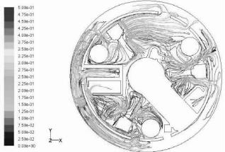
The velocity field of water flow in the containment is shown in Fig. 20. The water would tumble the sunken debris along the ground floor or lift debris over a curb in the area where the water velocity is high enough.
Fig. 20. Velocity field in containment
The experimental and numerical results gained above can provide necessary basis for the analysis of the properties of containment sump strainer and for the design of new-type containment sump strainers.
3.3 Test of control rod drive mechanism
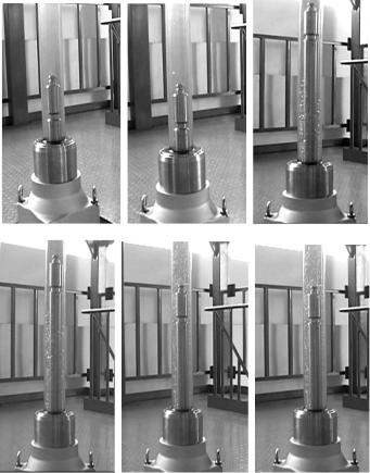
In the beginning tests of control rod drive mechanism (CRDM), two phase flow would come into being because there is air dissolved in the liquid and hidden in the groove of driving rod. The air would be decomposed from the water and be extruded out of the groove when there is disturbance. For example, electrifying of coil component, up-down movement of driving rod, swing in and out of gripper component would give rise to disturbance and make the bubbles appear in the liquid. There is small amount of air dissolved or hidden in the water and twophase flow would not occur in the test after CRDM moves several days.
In the tests, there is no bubble observed and the air would not be decomposed from the water when there is no disturbance, which is shown in Fig. 21(a). There are three coil components in CRDM, which are lifting coil, moving coil and stationary coil. And bubbles begin to come into being and there appear several separate bubbles when the coil component is electrifying and the gripper swings into the driving rod, which is shown in
200 |
Nuclear Power Plants |
(a) |
(b) |
(c) |
(d) |
(e) |
(f) |
Fig. 21. Rod lifting tests
Fig. 21(b). In the tests of rod lifting, the driving rod goes upwards, the electromagnet is engaged and grippers swing into and out of the driving rod one by one. At this time, large numbers of bubbles appear in the liquid and bubbly flow come into being, as shown in figures 21(c) ~(f). In the tests of rod inserting, the phenomenon of downwards movement of the driving rod is similar to that of upwards movement.
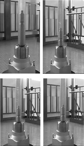
In the tests of rod dropping, the power of three coils is cut off, the grippers swing out of the driving rod, and the driving rod free falls in the rod travelling house. In this process, the disturbance is transitory and bubbles appear in the liquid, of which the amount is less than that of rod lifting. When the bubbles go up to the bottom of the test section and there is no disturbance again, no bubbles will generate in the liquid, as shown in Fig. 22.
In the cold tests of rod lifting, rod inserting and rod dropping, only bubbly flow comes into being due to that the amount of gas dissolved in the liquid is small. After CRDM moves several days, the gas dissolved are all driven out of the liquid and there will not appear twophase flow.
Investigation on Two-Phase Flow Characteristics in Nuclear Power Equipment |
201 |
(a) |
(b) |
(c) |
(d) |
Fig. 22. Rod dropping tests
4. Conclusion
On the basis of the experimental results, the conclusions are obtained,
(1)It is found that there are several main flow patterns, bubbly flow, bubbly-churn flow, churn flow and annular flow in the tube-bundle channel. And there are great differences between flow patterns and their transitions in a tube-bundle channel and that in a circular tube.
(2)Experiments show that there may be two different flow patterns in the same crosssection of the tube-bundle channel. And the flow pattern transitions exhibit unsynchronized in different sub-channels. This unsynchronized phenomenon is caused by the different geometric dimensions, different heat flux and different quantity of discrete bubbles generated in different sub-channels.
202 |
Nuclear Power Plants |
(3)The flow pattern map is drawn on the basis of experiments. Comparisons are conducted between flow pattern transition in a tube-bundle channel and that gained by Hewitt & Roberts. The results show that the regions of bubbly flow and churn flow in a tube-bundle channel are larger than that in a circular tube. In addition, the flow pattern transforming to annular flow is earlier in a tube-bundle channel than that in a circular tube.
(4)Three main tests are carried out to measure pressure drop of the containment sump strainers. The photographs are taken and the vortex is not observed in these tests.
(5)In the tests of control rod drive mechanism, two-phase flow is observed. The results of upwards movement and drop movement of the driving rod are compared and analyzed.
5. Acknowledgments
The authors would like to acknowledge the financial support from the National Science and Technology Program of China (Grant No. 2011BAA06B00). The authors would also like to thank Messrs. Yu Jiang., Zhou Jianming, Wu Wei, Bai Bing, Lu Zhaohui for the helpful discussions.
6. References
Bergles, A. E. (1981). Two-phase flow and heat transfer in the power and process industries. ISBN: 978-0070049024 , McGraw-Hill Inc., Washington, US
Chan A. M. C. & Shroukri M. (1987). Boiling characteristics of small multi-tube bundles. Journal of Heat Transfer. Vol.109, pp.753-760. ISSN 0022-1481, New York, USA
Grant I. D. R. & Chisolm D. (1979). Two-phase flow on the shell-side of a segmentally baffled shell and tube heat exchanger. Journal of Heat Transfer. Vol.101, pp.38-42, ISSN: 0022-1481
Hewitt, G. F. & Roberts, D. N. (1969). Studies of two-phase flow patterns by simultaneous X-ray and flash photography, Atomic Energy Research Establishment, ISSN: 0029-5450, Harwell, England
Lu, G. Y.; Ren, J. S.; Zhang, C. G. & Lin, P. (2011). Debris transport calculation of nuclear power plant containment, 19th International Conference On Nuclear Engineering, ISBN: 978-0-7918-4351-2, Osaka, Japan, October 24 - 25, 2011
Lu, G. Y.; Ren, J. S.; Zhang, C. G. & Lin, P. (2011). Investigation on pressure drop characteristics and disposal optimization of conflux channels of containment sump strainers, 19th International Conference On Nuclear Engineering, ISBN: 978-0-7918- 4351-2, Osaka, Japan, October 24 - 25, 2011
Lu, G. Y.; Ren, J. S.; Zhang, C. G. & Xiang, W. Y. (2011). Application and development of containment sump strainers in PWR power stations in China, 19th International Conference On Nuclear Engineering, ISBN: 978-0-7918-4351-2, Osaka, Japan, October 24 - 25, 2011
Ma Weimin. (1992). Experimental investigations on two-phase flow in heat exchangers.
Xi’an Jiaotong University, ISSN: 1671-8267
Petigrew, M. J. & Taylor C. E. (1994).Two-phase flow-induced vibration. Journal of Pressure Vessel Technology, Vol.166, pp. 233-253, ISSN: 0094-9930
Sadatomi, M. & Kawahara, A. (2004). Flow characteristics in hydraulically equilibrium twophase flows in a vertical 2×3 rod bundle channel. International Journal of Multiphase Flow, Vol.30, pp.1093–1119, ISSN: 0301-9322
8
Analysis of Primary/Containment Coupling
Phenomena Characterizing the MASLWR
Design During a SBLOCA Scenario
Fulvio Mascari1, Giuseppe Vella1, Brian G. Woods2,
Kent Welter3 and Francesco D’Auria4
1Department of Energy, The University of Palermo
2Department of Nuclear Engineering and Radiation Health Physics
Oregon State University
3NuScale Power Inc.
4San Piero a Grado - Nuclear Research Group (SPGNRG), University of Pisa
1,4Italy
2,3USA
1. Introduction
Today considering the world energy demand increase, the use of advanced nuclear power plants, have an important role in the environment and economic sustainability of country energy strategy mix considering the capacity of nuclear reactors of producing energy in safe and stable way contributing in cutting the CO2 emission (Bertel & Morrison, 2001; World Energy Outlook-Executive Summary, 2009; Wolde-Rufael & Menyah, 2010; Mascari et al., 2011d). According to the information’s provided by the “Power Reactor Information System” of the International Atomic Energy Agency (IAEA), today 433 nuclear power reactors are in operation in the world providing a total power installed capacity of 366.610 GWe, 5 nuclear reactors are in long term shutdown and 65 units are under construction (IAEA PRIS, 2011).
In the last 20 years, the international community, taking into account the operational experience of the nuclear reactors, starts the development of new advanced reactor designs, to satisfy the demands of the people to improve the safety of nuclear power plants and the demands of the utilities to improve the economic efficiency and reduce the capital costs (D'Auria et al., 1993; Mascari et al., 2011c). Design simplifications and increased design margins are included in the advanced Light Water Reactors (LWR) (Aksan, 2005). In this framework, the project of some advanced reactors considers the use of emergency systems based entirely on natural circulation for the removal of the decay power in transient condition and in some reactors for the removal of core power during normal operating conditions (IAEA-TECDOC-1624, 2009; Mascari et al., 2010a; Mascari et al., 2011d). For example, if the normal heat sink is not available, the decay heat can be removed by using a passive connection between the primary system and heat exchangers (Aksan, 2005; Mascari et al., 2010a, Mascari, 2010b). The AP600/1000 (Advanced Plant 600/1000 MWe) design, for
204 |
Nuclear Power Plants |
example, includes a Passive Residual Heat Removal (PRHR) system consisting of a C-Tube type heat exchanger immersed in the In-containment Refueling Water Storage Tank (IRWST) and connected to one of the Hot Legs (HL) (IAEA-TECDOC-1391, 2004; Reyes, 2005c; Gou et al., 2009; Mascari et al., 2010a). A PRHR from the core via Steam Generators (SG) to the atmosphere, considered in the WWER-1000/V-392 (Water Moderated, Water Cooled Energy Reactor) design, consists of heat exchangers cooled by atmospheric air, while the PRHR via SGs, considered in the WWER-640/V-407 design, consists of heat exchangers immersed in emergency heat removal tanks installed outside the containment (Kurakov et al., 2002; IAEA-TECDOC-1391, 2004; Gou et al., 2009; Mascari et al., 2010a). In the AC-600 (Advanced Chinese PWR) the PRHR heat exchangers are cooled by atmospheric air (IAEATECDOC 1281, 2002; Zejun et al., 2003; IAEA-TECDOC-1391, 2004; Gou et al., 2009; Mascari et al., 2010a) and in the System Integrated Modular Advanced Reactor (SMART) the PRHR heat exchangers are submerged in an in-containment refuelling water tank (IAEA-TECDOC- 1391, 2004; Lee & Kim, 2008; Gou et al., 2009; Mascari et al., 2010a). The International Reactor Innovative and Secure (IRIS) design includes a passive Emergency Heat Removal System (EHRS) consisting of an heat exchanger immersed in the Refueling Water Storage Tank (RWST). The EHRS is connected to a separate SG feed and steam line and the RWST is installed outside the containment structure (Carelli et al., 2004; Carelli et al., 2009; Mascari, 2010b; Chiovaro et al., 2011). In the advanced BWR designs the core water evaporates, removing the core decay heat, and condenses in a heat exchanger placed in a pool. Then the condensate comes back to the core (Hicken & Jaegers, 2002; Mascari et al., 2010a). For example, the SWR-1000 (Siede Wasser Reaktor, 1000 MWe) design has emergency condensers immersed in a core flooding pool and connected to the core, while the ESBWR (Economic Simplified Boiling Water Reactor) design uses isolation condensers connected to the Reactor Pressure Vessel (RPV) and immersed in external pools (IAEA-TECDOC-1391, 2004; Aksan, 2005; Mascari et al., 2010a).
The designs of some advanced reactors rely on natural circulation for the removing of the core power during normal operation. Examples of these reactors are the MASLWR (MultiApplication Small Light Water Reactor), the ESBWR, the SMART and the Natural Circulation based PWR being developed in Argentina (CAREM)(IAEA-TECDOC-1391, 2004; IAEA -TECDOC-1474, 2005; Mascari et al., 2010a). In particular the MASLWR (Modro et al., 2003), figure 1, is a small modular integral Pressurized Water Reactor (PWR) relying on natural circulation during both steady-state and transient operation.
In the development process of these advanced nuclear reactors, the analysis of single and two-phase fluid natural circulation in complex systems (Zuber, 1991; Levy, 1999; Reyes & King, 2003; IAEA-TECDOC-1474, 2005; Mascari et al., 2011e), under steady state and transient conditions, is crucial for the understanding of the physical and operational phenomena typical of these advanced designs. The use of experimental facilities is fundamental in order to characterize the thermal hydraulics of these phenomena and to develop an experimental database useful for the validation of the computational tools necessary for the operation, design and safety analysis of nuclear reactors. In general it is expensive to design a test facility to develop experimental data useful for the analyses of complex system, therefore reduced scaled test facilities are, in general, used to characterize them. Since the experimental data produced have to be applicable to the full-scale prototype, the geometrical characteristics of the facility and the initial and boundary