

NUCLEAR POWER PLANTS
.pdfThe Gap Measurement Technology and Advanced RVI |
135 |
Installation Method for Construction Period Reduction of a PWR |
2.2 Measurement sensor
Many essential factors in selecting a measurement sensor for the RVI modularization were studied. Namely, the measurement environment, the measured object, size of the sensor, the weight of a sensor, measurement range, drive force of the sensor, accuracy and resolution were investigated
First, contact sensors and non-contact sensors were compared (Ko et al., 2009) (ABB-CE, 1995).
Contact sensors are used to directly measure distance by moving the sensors toward the measured object. Non-contact sensors are used to indirectly measure comparatively very small distances by laser, high frequency and eddy current(Figliola & Beasley, 2000)( Beckwith et al., 1993).
Contact sensors are more suitable than non-contact sensors. Non-contact sensors are not ideal because their outside diameter is bigger than the hole diameter 8 [mm] of the CSB snubber lug, the measurement range is smaller than it is with contact sensors, and, most importantly, design changes to the CSB snubber lug are bigger in non-contact sensors than in contact sensors.
The most important principle can be directly applied without design changes to the existing reactor internals. The contact sensor of a remote distance measurement sensor must be inserted into the measurement hole of CSB snubber lug. Therefore, an essential condition of a sensor must be a probe type because a measurement sensor must pass through the measurement hole of the CSB snubber lug. The outside diameter must be 8 [mm] or less since the measured diameter of the hole in the CSB snubber lug is 8 [mm]. The length of the probe head must be 117.6 [mm] or more because the end point of the measurement hole in the CSB snubber lug must reach the RV after a zero point adjustment. Also, a sensor must span the distance from the CSB snubber lug to the RV when the RV and CSB are assembled, thus requiring the backward probe head to be 147.3 [mm] or less. Measurement range can be measured from 50 [mm].
The previous measurement was done by hand-measurement and the measured maximum value was 48.92 [mm] (Uljin #5 nuclear power plant in Korea). The resolution must be 0.0254 [mm] or below as the sensor has to measure until 0.0254 [mm] (1/1000”) in the case of gap measurement between the CSB snubber lug and the shim on the RV core-stabilizing lug, after the shim was assembled onto the CSB snubber lug by cap screws.
A sensor was investigated that remote measurement was possible in at least 25 [m] or more. The following items were considered when selecting a sensor: material, space and outward shape of the reactor internals. Also, no additional devices should be installed around the RV core stabilizing lug and the CSB snubber lug in order to perform the remote measurement.
Table 1 shows the suitable specifications of a sensor that have been researched to measure gap. The shape of a sensor is probe type of a contact sensor and the measurement method is digital.
Finally, the SOLARTRON (UK) sensor (DT/20/P) was selected for the reduced-scale model system (Solartron-metrology, 2006).

136 |
Nuclear Power Plants |
||
|
|
|
|
|
Shape of sensor |
Probe |
|
|
Type of sensor |
Contact, Digital |
|
|
Outside diameter of probe head |
8 [mm] or below |
|
|
Length of probe head |
117.6 [mm] or over |
|
|
Backward space of CSB snubber lug hole |
From hole entrance 147.3 [mm] or below |
|
|
Measurement range |
50 [mm] or over |
|
|
Resolution |
25.4 [um] or below |
|
|
Accuracy |
±12.7 [um] or below |
|
|
Operating temperature |
No relation |
|
|
Distance of remote measurement |
25 [m] or over |
|
|
Driving force |
Electric or Pneumatic |
|
|
Numbers of synchronous measurement |
72 points and over |
|
|
Operating tool |
Computer-based |
|
Table 1. Suitable specifications of a remote sensor for gap measurement
2.3 Experiment and result
The designed system was tested to confirm the performance and application conditions of a remote distance measurement sensor selected.
The tests were carried out repeatedly to confirm reliability, consistency, accuracy and stability of the measurement.
The reliability test method of the sensors is as follows. First, a sensor was fixed to an anchor of granite comparator stand. Second, the probe of the sensor is positioned so as to be close to the granite comparator stand at suitable heights. Third, the probe was extended so that it touches on the face of stand. This state is the zero point of the sensor. Forth, put gauge blocks of 5 [mm], 10 [mm], 15 [mm], and 18 [mm] on the stand, and measure the reliability of the sensor. Reliability test results were obtained as shown in Fig. 7.
As the size of a gauge block is large, the error of measurement sensor was increased from 0.0037 [mm] to 0.0119 [mm]. However, the reliability test was satisfied because the sensors did not exceed the maximum allowable error (0.0254 [mm]). And the measurement errors under the pressure of 0.8 [bar] and 2 [bar] are similar.
Fig. 7. Reliability test results of remote distance measurement sensors using gauge blocks
The Gap Measurement Technology and Advanced RVI |
137 |
Installation Method for Construction Period Reduction of a PWR |
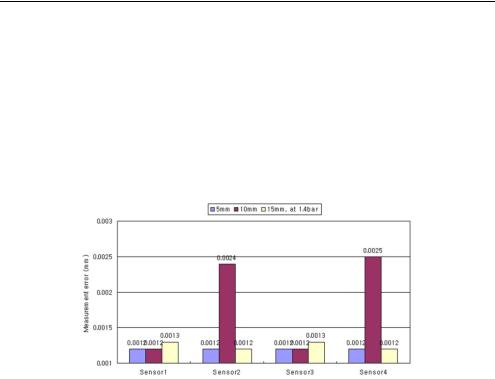
The consistency test method of connection jigs for sensors is as follows. First, a sensor was inserted into a threaded connection jig and fixed firmly. Second, insert a sensor and a connection jig to the hole of the minimized model of the CSB snubber lug, and fix it firmly by threaded connection jig. Third, when sensors have received air pressure of 0.8[bar], 1.4[bar], and 2.0[bar], the sensors measure the distance five times. Fourth, the process measurements are repeated three times and attached again after removing the connection jigs of the remote distance measurement sensors. Consistency test results under 1.4[bar] at each gauge blocks were obtained as shown in Fig. 8.
The measurement errors of sensor 2 (0.0024 [mm]) and 4 (0.0025 [mm]) were large compared with sensor 1 and 3, but consistency test were satisfied because the error did not exceed the maximum allowable error.
Fig. 8. Consistency test results of connection jigs for remote sensors
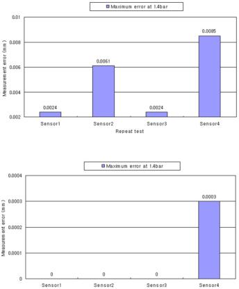
The accuracy test method for the zero point adjustment device for the sensors is as follows. First, a zero point adjustment device that was designed and made, binds the right and left of the minimized model of the CSB, and is fixed. Second, run the probes of the sensors installed into the minimized model of the CSB, and remove the zero point adjustment device on the minimized model of the CSB after repeating the distance measurement five times. Third, compare the distance measurements from three repetitions of the process. Accuracy test results were obtained as shown in Fig. 9.
The measurement errors of sensor 2 and 4 were large compared with sensor 1 and 3, but accuracy test were satisfied because it did not exceed the maximum error.
Switching noises and EMI (electromagnetic interference) might occur because of the use of electric lamps and transceivers to build nuclear power plants (Ko & Bae, 2006).
Therefore, the stability tests were done at no disturbance noise and in a switching noise environment, and at EMI environment.
The stability test method of sensors at no disturbance noise is as follows. The air pressure to 1.4[bar] on the remote sensors of the reduced-scale model system was set up and tested five times, repeatedly. Stability test results at remote distance were obtained as shown in Fig. 10.
There were no errors in all sensors except sensor 4. The error was only 0.0003 [mm], but it was in allowable range.
138 |
Nuclear Power Plants |
Fig. 9. Accuracy test results of a zero point adjustment device for sensors
Fig. 10. Stability test results of sensors at no disturbance noise
The stability test method of the sensors in a switching noise environment is as follows. First, a 27[W] desk lamp (220V/60Hz) at 10 [cm] from the sensor probe was installed. Second, five times while turning the power on the lamp on and off were measured. During this test, the supplied air pressure was 0.8[bar] to the the sensor probe. The results at switching noise environment were obtained as shown in Fig. 11.
The measurement errors of sensor 2 and 4 were 0.0012 [mm] and 0.0008 [mm], but it were satisfied because the sensors did not exceed the maximum error (0.0254 [mm]).
Another stability test methods of the sensors at EMI environment is as follows. First, a VHF/UHF FM radio transceiver (TM-V7A/KENWOOD) and an antenna 30 [cm] away from the probes were installed. Second, five times each for the cases of 144[MHz/5W], 144[MHz/10W], 439[MHz/5W] and 439[MHz/10W] were repeatedly measured. During this test, the supplied air pressure was 0.8[bar] to the probes of the sensors. The test results at EMI environment were obtained as shown in Fig. 12.
In the environment of 144 [MHz/10W], the measurement error was 0.0003 [mm], but it was in allowable range also.

The Gap Measurement Technology and Advanced RVI |
139 |
Installation Method for Construction Period Reduction of a PWR |
Fig. 11. Stability test results at switching noise environment
Fig. 12. Stability test results at EMI environment
As shown in the above test results, the selected sensor can be used in a remote measurement system for the modularization of reactor internals since the sensor errors did not exceed 0.0254 [mm] (1/1000”).
In the experiments and results, they were found that the measurement errors of sensor 2 and sensor 4 are bigger than sensor 1 and sensor 3. We judged that these results were occurred by something problem from self-characteristics of sensors.
2.4 Conclusion
From these results, the technology of remote measurement for the modularization of reactor internals may be advanced by design and development of the reduced-scale model system.
Also, the reduced-scale model system designed may be used as a gap measurement training system for a modularization method of reactor internals. And it needs the more suitable sensor under the consideration of the special conditions and environments in reactor internals.
140 |
Nuclear Power Plants |
3. Development of measurement system for RVI modularization
An RV mockup and a CSB mockup were also manufactured to evaluate and verify the reliability and applicability in construction sites of the developed remote measurement system. This part explains the development of the remote measurement system, including its design, fabrication and related experiments (Ko & Lee, 2010).
3.1 Development of a remote measurement system for gap measurements 3.1.1 Design
The purpose of this remote measurement design is to measure the gaps of between the RV core-stabilizing lug and the CSB snubber lug for RVI-modularization. The reason for the measurement of gaps is to set a permissible range of 0.381 – 0.508 mm between the RV corestabilizing lug and the CSB snubber lug. The permissible range, when a nuclear reactor operates, ensures a margin by thermal expansion. This is identical to that used in current power water reactors.
For these gaps, adjustment of the shims was machined at the construction site and assembled in the RV after measurement of the gaps of the RV core-stabilizing lugs and the CSB snubber lugs.
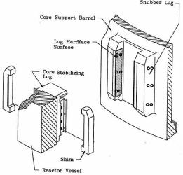
Fig. 4 shows the placement of the six gap-measurement locations between the RV corestabilizing lug and the CSB snubber lug. The RV core-stabilizing lugs located inside the RV and the CSB snubber lugs located outside the CSB are set at angles of 0°, 60°, 120°, 180°, 240°, and 300°. The angular positions correspond to locations 1 through 6, respectively (see Fig. 4). Also, each of six RV core-stabilizing lugs corresponds to a pair of (left and right) the CSB snubber lugs, as shown in Fig. 4. One side of the CSB snubber lug has six holes for handmeasurements in the current RVI-installation method. Therefore, one CSB snubber lug has twelve holes, and six CSB snubber lugs have a total of 72 holes, which are from the external RVI; the lengths of which should be measurable simultaneously, as shown in Fig. 13.
Fig. 13. RV core-stabilizing lug and CSB snubber lug

The Gap Measurement Technology and Advanced RVI |
141 |
Installation Method for Construction Period Reduction of a PWR |
Many essential factors were studied before selecting the measurement sensors used for RVImodularization.
Specifically, the measurement environment, the measured object, the size of the sensor, the weight of the sensor, the measurement range, the driving force of the sensor, the accuracy, and the resolution were investigated. Finally, the SOLARTRON (UK) sensor (DT/20/P) was selected for the remote measurement system (Ko et al., 2009).
The DT/20/P sensor was tested to confirm its performance and application conditions in a reliability test using gauge blocks. A consistency test was also done to check the connection jig, and an accuracy test was done for the zero-point adjustment device. Finally, a stability test was done to check the switching noise environment and the EMI (electromagnetic interference) using a reduced-scale model system. All test results were satisfactory for a sensor of a remote measurement system (Ko et al., 2009).
3.1.2 Fabrication
A remote measurement system was developed to measures the gaps between the RV corestabilizing lug and the CSB snubber lug using a DT/20/P digital probe sensor. The major characteristics of the remote measurement system are as follows:
-The remote measurement system consists of a measurement sensor section, a pneumatic supply and control section, a power supply section, and a remote control computer and software program.
-The measurement sensor section is intended to measure gaps between the RV corestabilizing lug and the CSB snubber lug. Those sensors, placed at 0° and 60°, are measured by 24 sensors with a signal cable connected to the channel box #1. Those sensors placed at 120° and 180° are measured by 24 sensors with a signal cable connected to the channel box #2, and those sensors placed at 240° and 300° are measured by 24 sensors with a signal cable to connected the channel box #3. A measurement sensor section is composed of 72 digital probes. This system is able to measure 72 points at once and operate by pneumatic actuation.
-The pneumatic supply and control section is intended to supply air to actuate the sensors by a remote control computer and a software program. The pneumatic supply section consists of an air compressor, an air filter, an air pressure regulator and an air tube. The pneumatic control section is composed of a flow control valve, a solenoid valve, a solenoid valve manifold, a USB orbit module and a T-CON. The solenoid valve and the solenoid valve manifold control operation of measurement sensors and the USB orbit module and the T-CON receive signal data of the digital probe, DT/20/P.
-The power supply section supplies electric power to the electric equipment, including the T-CON.
-The remote control computer and the software program consist of a laptop computer and the software to control digital probes and to process and store the measurement results.
-The channel box contains 24 digital probes, the T-CON, 24 solenoid valves, and four solenoid valve manifolds. The channel is designed for three channel boxes. These boxes were very easy to handle due to their suitable weight and size.
-All of the cables and air tubes are easily connected to the channel boxes.
-The network of the remote measurement system is very stable and causes no disturbance to the EMI environment.
142 |
Nuclear Power Plants |
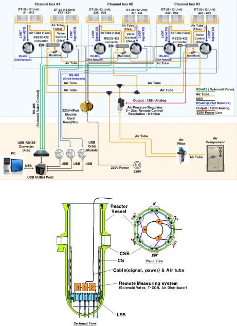
Fig. 14. Block diagram of developed remote measurement system
Fig. 15. Setup position of the remote measurement system
Table 2 presents a list of the parts of the remote measurement system, and Fig. 14 shows a block diagram of the developed remote measurement system.
The Gap Measurement Technology and Advanced RVI |
143 |
||
Installation Method for Construction Period Reduction of a PWR |
|||
|
|
|
|
|
List of Parts |
Amount |
|
|
DT/20/P digital probe |
72 |
|
|
USB orbit module |
3 |
|
|
AC-PSIM power supply |
6 |
|
|
T-CON |
75 |
|
|
Flow control valve |
72 |
|
|
Threaded connection jig |
72 |
|
|
0-Point adjustment jig |
6 |
|
|
Solenoid valve |
72 |
|
|
Solenoid valve manifold |
12 |
|
|
2-line RS-485 signal cable & reel |
3 |
|
|
220V-4port electric cable & cord reel |
2 |
|
|
Air tube |
500 m |
|
|
4-port air manifold |
1 |
|
|
I/O board SMPS |
9 |
|
|
4-port USB hub |
1 |
|
|
USB to RS-485 converter |
1 |
|
|
Air clean unit |
2 |
|
|
Air compressor |
1 |
|
|
Marking tool |
1 |
|
|
Electric lamp & cord reel |
2 |
|
|
Air tube one touch reel(20 m) |
1 |
|
|
System storage box |
1 |
|
Table 2. List of parts for remote measurement system |
|
|
|
As shown in Fig. 15, the channel boxes are located above the LSS in the CSB. The digital probes should be set on the CSB snubber lugs before assembly with the RV. The channel box should be connected to the air compressor, to the remote control computer, and to the electric power source after assembly of the RV and the CSB.
3.2 Design of RV and CSB mockup
An RV mockup and a CSB mockup were designed and manufactured because the remote measurement system should be subjected to a test to verify its applicability in construction projects. This was done using the RV mockup and the CSB mockup developed here.
3.2.1 Design concept of the RV and the CSB mockup
To design the RV mockup and the CSB mockup, it was necessary to follow a number of principles. First, the measurement parts of the RV core-stabilizing lugs and the CSB snubber lugs should be designed to simulate the actual size of the construction site. Second, the 72 points of the RV core-stabilizing lugs and the CSB snubber lugs should be measured simultaneously. The factors not related to any measurement part should be designed to be as simple as possible.
The RV mockup and the CSB mockup were designed to evaluate the setting suitability of remote measurement system. In particular, the RV core-stabilizing lug of the RV mockup and the CSB snubber lug of the CSB snubber lug were designed to match the RV and the CSB of an actual nuclear power plant.
144 |
Nuclear Power Plants |
Other parts of the actual RV and CSB were simply designed for usability of the experiment and out of concerns for the manufacturing budget. Thus, the thickness of cylinders was designed to be thinner than that of an actual RV and an actual CSB.
3.2.2 Design of the RV mockup
The RV inner diameter is identical to that of the original. However, the RV outer diameter, not related to the measurement, was designed so as to be thinner, making it a light RV mockup. Thus, it was designed to be different from the actual size. The RV upper flange was simply designed.
The RV upper flange-face was assembled with the CSB and was applied to actual conditions in the same manner. The RV cylinder was designed with a thin plate, including a RV corestabilizing lug. The height of the RV mockup was minimized to 2,665 mm.
The assembled parts of the RV core-stabilizing lugs, the RV core stop lug, and the shim were designed to be identical to their real-life counterparts.
Six supports of 70 cm in height were attached to the bottom of the RV mockup to monitor the condition of the measurement sensors. The lifting lugs were welded onto the RV upper flange to facilitate assembly and separation from the CSB mockup.
Fig. 17 and Fig. 18 show the designed 3D model and an image of the manufactured RV mockup.
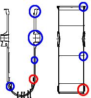
RV Flange |
CSB Flange |
|
|
||
Outlet Nozzle |
|
|
RV Cylinder |
CSB Cylinder |
|
Core Stabilizing Lug |
|
|
Core Stop |
CSB Snubber Lug |
|
Lug |
||
|
Fig. 16. Important parts of the design of the mockup
Other parts of the actual RV and CSB were simply designed for usability of the experiment and out of concerns for the manufacturing budget. Thus, the thickness of cylinders was designed to be thinner than that of an actual RV and an actual CSB.
Fig. 16 shows the important parts in the design of the RV mockup and the CSB mockup.
3.2.3 Design of the RV mockup
The RV inner diameter is identical to that of the original. However, the RV outer diameter, not related to the measurement, was designed so as to be thinner, making it a light RV