

NUCLEAR POWER PLANTS
.pdfEvolved Fuzzy Control System for a Steam Generator |
35 |
A Client / Server architecture for evolved controller that runs on the Windows environment, with real-time characteristics is proposed.
5. Acknowledgment
Parts of this chapter are reprinted from Hossu, D. Fagarasan, I., Hossu, A., Iliescu, S. St., Evolved fuzzy control system for a steam generator, Int. Journal of Computers, Communications and Control, IJCCC, ISSN 1841-9836, E-ISSN 1841-9844, Vol. V (2010), No.2, pp. 179 – 192.
6. References
Andone, D. ,Dobrescu, R., Hossu, A. & Dobrescu, M. (2006) Application of fuzzy model predictive control to a drum boiler , ICAE - Integrated Computer-Aided Engineering, IOSPress, vol.13, nr.4, ISSN 1069-2509, pp. 347-361.
Andone, D.& Hossu, A. (2004) Predictive Control Based on Fuzzy Model for Steam Generator, 2004 IEEE International Conference on Fuzzy Systems, Proc. FUZZ-IEEE 2004, vol. 3, IEEE Catalog Number 04CH37542, ISBN 0-7803-8353-2, ISNN 10987584, Budapest, Hungary; pp. 1245-1250; July 25-29.
Hossu, D., Fagarasan, I., Hossu, A. & Iliescu, S. St. (2010) Evolved fuzzy control system for a steam generator, Int. Journal of Computers, Communications and Control, IJCCC, ISSN 1841-9836, E-ISSN 1841-9844, Vol. V , No.2, pp. 179 – 192.
ÄstrÖm, K. & Bell, R. (2000) Drum-boiler dynamics, Automatica 36, pp. 363-378. Camacho, E. & Bordons, C. (2004) Model Predictive Control, Springer-Verlag, London.
Demircioglu, H.& Karasu, E. (2000) Generalized Predictive Control – A Practical Application and Comparation of Discrete and Continuous-Time Versions, IEEE Control Systems, Oct 2000, vol 20, nr. 5, pp 36-44.
Dubois, D.& Prade, H. (1997) Fuzzy Sets and Systems: Theory and Applications, Academic Press, Inc., Orlando, FL.
Espinosa, J., Hadjili, M. L.& Wertz, V., J.(1999) Predictive control using fuzzy models – Comparative study, European Control Conference, Karlsruhe, Germany, Sept. 1999.
Hirota, K. (1993) Industrial Applications of Fuzzy Technology, Springer-Verlag, New York. Huang, Y., Lou Helen, H., Gong, J.P.& Edgar, Th. F. (2000) Fuzzy Model Predictive Control,
IEEE Trans. On Fuzzy Systems, vol. 8, no. 6, Dec. 2000, pp. 665-668.
Irving, E., Miossec, C.& Tassart, J. (1980) Toward efficient full automatic operation of the PWR steam generator with water level adaptive control, Proc. Int. Conf. Boiler Dynamics Contr. Nuclear Power Stations, London, U.K., pp. 309-329.
Kiriakidis, K. (1999) Non-linear control system design via fuzzy modeling and LMIs,
International Journal of Control, Vol. 72, no. 7, pp. 676-685.
Kothare, M., Mettler, B., Morari, M., Bendotti, P.& Falinower, C. (2000) Level Control in the Steam Generator of a Nuclear Power Plant, IEEE Trans. On Control Systems Technology, vol. 8, no. 1, Jan. 2000, pp. 55-69.
Menon, S.K. & Parlos, A.G. (1992) Gain-scheduled nonlinear control of U-tube steam generator water level, Nuclear Sci. Eng., vol. 111, pp. 294-308.
Morari, M. & Lee, J. H. (1999) Model predictive control: Past, present, and future, Computers & Chemical Eng., pp. 667-682.

36 Nuclear Power Plants
Park, G. Y. & Seong, P. H. (1997) Application of a self-organizing fuzzy logic controller to nuclear steam generator level control, Nuclear Engineering and Design., vol. 167, pp. 345-356.
Pedrycz, W. & Gomide, F. (2007) Fuzzy Systems Engineering: Toward Human-Centric Computing, Wiley-IEEE Press.
Ross, T.J. (2004) Fuzzy Logic with Engineering Applications, second ed. Wiley & Sons.
Yager, R., R. & Zadeh, L. (1992) A., An Introduction to Fuzzy Logic Applications in Intelligent Systems, Kluwer Academic Publishers, Norwell, MA.
Yen, J., Langari, R. & Zadeh, L.(1995) A., Industrial Applications of Fuzzy Logic and Intelligent Systems, IEEE Press, Piscataway, NJ.
Ying, H. (2000) Fuzzy Control and Modeling: Analytical Foundations and Applications, WileyIEEE Press.
Zadeh, L. (2008) A New Frontier in Computation - Computation with Information Described in Natural Language, International Journal of Computers Communications and Control, Volume:3, Supplement: Suppl. S, pp. 26-27, 2008.
Zadeh, L. A. (2005) Toward a generalized theory of uncertainty (GTU): an outline,
Information Sciences-Informatics and Computer Science: An International Journal, v.172 n.1-2, p.1-40, 9 June 2005.
Zadeh, L. A. (1989) Knowledge Representation in Fuzzy Logic, IEEE Transactions on Knowledge and Data Engineering, v.1 n.1, p.89-100, March 1989.
Zhao, F., Ou, J. & Du, W. (2000) Simulation modeling of nuclear steam generator water level process – a case study, ISA Transactions 39, pp. 143-151.
3
Deterministic Analysis of Beyond Design
Basis Accidents in RBMK Reactors
Eugenijus Uspuras and Algirdas Kaliatka
Lithuanian Energy Institute
Lithuania
1. Introduction
RBMK reactor belongs to the class of graphite-moderated nuclear power reactors that were designed in the Soviet Union in the 1950s. The usage of materials with low neutron absorption in RBMK design allows improving the fuel cycle by using cheap low-enriched nuclear fuel. In total 17 RBMK reactors have been built in Russia, Ukraine and Lithuania. One reactor is still under construction at Kursk Nuclear Power Plant (NPP). All three surviving reactors at Chernobyl NPP (Ukraine) were shutdown (the fourth was destroyed in the accident). Units 5 and 6 at Chernobyl NPP were under construction at the time of the accident; however, further construction was stopped due to the high contamination level at the site and political pressure. In Lithuania two reactors at Ignalina NPP were shutdown in 2004 and 2009. At present time no plans are made to build new RBMK type reactors, but in 2011, 11 RBMK reactors are still operating in Russia (4 reactors in Saint Petersburg, 3 – in Smolensk and 4 – in Kursk).
The RBMK reactor is a channel-type boiling water reactor. It has a huge graphite block structure, which functions as a moderator that slows down the neutrons produced by fission. The feature of RBMK type reactor is that each fuel assembly is positioned in its own vertical fuel channel, which is individually cooled by boiling water that is intended to remove the heat produced in it. The fuel channels are made of Zirconium and Niobium alloy similar to that used for fuel claddings. Reactor cooling system of RBMK has two loops, which are interconnected via the steamlines and do not have a connection on the water part. This is a difference from the vessel-type reactors.
The RBMK type reactors do not have full containment, preventing the environment from the radioactive material release. The absence of an overall containment suggests that in case of severe accident, the mitigation of fission products release to environment has to be based primarily on decreasing the extent of core damage, which is a key factor for the radiological consequences of accidents in RBMK. The degree of core damage is determined by the RBMK characteristics, such as the ability of the circulation loop to disintegrate and the multichannel nature of the core. Thus, depending on the type of accident, the damage of fuel assemblies can remain localized within a single fuel channel, a group of channels connected to the same group distribution header, or channels of a single loop (half of the core) or it can propagate to the entire core if complete loss of cooling occurs. Consequently, the severity of RBMK core damage depends on the degree and number of damaged fuel assemblies.
38 |
Nuclear Power Plants |
Another characteristic feature of RBMK is the graphite moderator. A positive property of such moderator is high heat capacity, which increases voided core heating time. This gives the operators more time to control the accident and to restore the failed equipment. At the same time, the existence of the graphite requires additional estimation of the graphite behavior at high temperature.
The mentioned specifics of RBMK reactors are affected on the design basis and beyond design basis accident sequences and necessary accident management measures, which are completely different from those in vessel type boiling water reactors. To understand the specifics of accidents in RBMK reactors the consequences of different accident groups were modeled by employing system thermal-hydraulic computer codes. This chapter presents the specifics of RBMK reactors, categorization of the Beyond Design Basis Accidents (BDBA) and specifics of the deterministic accident analyses in BDBA in RBMK. The results of the analysis were used for the development of Symptom-Based Emergency Operating Procedures and reactor cooldown strategies in case of beyond design basis accidents.
2. Specifics of RBMK reactors
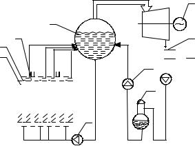
A simplified heat flow diagram of RBMK reactor is provided in Figure 1 [1]. The reactor cooling water, as it passes through the core, is subjected to boiling in the fuel channels (2) and is partially evaporated. The steam-water mixture then continues to the large drum separator (3), the elevation of which is greater than that of the reactor. The water settles there, while the steam proceeds to the turbines (5). The remaining steam beyond the turbines is condensed in the condenser (7), and the condensate is supplied by the condensate pumps (8) into the deaerator (9). Deaerated water is returned by the feed pump (10) to the drum separator (4). The coolant mixture is returned by the main circulation pumps (11) to the core, where a part of it is again converted to steam. The reactor power is controlled using control rods (3).
4
3
2
1 
 Reactor
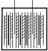
5  6
6
7

 8 10
8 10 

9
11
Fig. 1. Simplified RBMK-1500 heat flow diagram: 1 – graphite moderator; 2 - fuel channel; 3
– control rod; 4 - Drum Separator (DS); 5 - turbine; 6 - generator; 7 - condenser; 8 - condensate pump; 9 - deaerator; 10 - feedwater pump; 11 - main circulation pump

Deterministic Analysis of Beyond Design Basis Accidents in RBMK Reactors |
39 |
This fundamental heat cycle is identical to the Boiling Water Reactor cycle, extensively used throughout the world, and is analogous to the cycle of thermal generating stations. However, compared to BWRs used in Western power plants, the RBMK-1500 and RBMK1000 have a number of unique features. The comparison of most important parameters of the reactor is presented in Table 1. As it is seen from the presented table, the values of specific power per fuel quantity are very similar for all reactors. The value of power per fuel rod length is the highest for RBMK-1500 reactor. To reach such high value, additional specifically designed spacers, which operate like turbulence enhancers to improve the heat transfer characteristics, are mounted in the fuel assemblies of RBMK-1500. Specific power per core volume in RBMK-1500 is higher than in RBMK-1000 reactor, but in BWR-type reactors this characteristic is approximately 10 times higher.
No. |
Parameter |
BWR* |
RBMK-1000 RBMK-1500 |
|
1. |
Thermal power, MW |
3800 |
3840 |
4800 |
2. |
Core diameter m |
5.01 |
11.80 |
11.80 |
3. |
Core height, m |
3.81 |
7.0 |
7.0 |
4. |
Core volume, m3 |
75 |
765 |
765 |
5. |
Mean specific power per core volume, MW/m3 |
51 |
5.02 |
6.27 |
6. |
Mean specific power per fuel quantity, MW/t |
24.6 |
20.8 |
26.0 |
7. |
Mean power per fuel rod length, kW/m |
19.0 |
18.3 |
22.9 |
|
|
|
|
|
* General Electric design
Table 1. Comparison of BWR and RBMK reactor parameters
In RBMK-type reactors a part of Reactor Cooling System (RCS) above the reactor core is located outside the leaktight compartments. In the RBMK reactors design, these compartments are called Accident Localization System (ALS). This is different from the typical PWR or BWR plants, which have full containment [1]. The Drum Separators (DS) and a part of downcomers are contained in the DS compartments, which are connected to the reactor hall. Such compartments are not as strong as the leaktight compartments of ALS.
2.1 Specifics of RBMK reactor core
Nuclear fuel used in the RBMK-1500 (the reactor of Ignalina NPP in Lithuania) is slightly enriched with uranium in the form of uranium dioxide. According to RBMK-1500 design, low-enriched (2%) uranium fuel was used since the begging of Ignalina NPP exploitation. Later this fuel was mostly fully replaced by a little higher-enrichment (2.4% and 2.6%; 2.8%) uranium fuel with a burnable erbium absorber. The change of fuel allows improving safety and economic parameters of the plant.
Fuel pellets have a 11.5 mm outer diameter and are 15 mm long. The fuel pellets have hemispherical indentations in order to reduce the fuel column thermal expansion and thermo-mechanical interaction with the cladding. The 2 mm diameter hole through the axis of the pellet reduces the temperature at the center of the pellet, and helps to release the gases formed during the operation. The pellets placed into a tube with an outside diameter of 13 mm compose a fuel rod. The active length of RBMK-1500 fuel rod is approximately 3.4 m.
40 |
Nuclear Power Plants |
The tube (fuel cladding) material of the fuel rod is an alloy of zirconium with one percent niobium. The fuel rods are pressurized with helium and sealed. The fuel pellets are held in place by a spring. 18 fuel rods, arranged within two concentric rings in a central carrier rod, contain the fuel bundle with an inside diameter of 8 cm [1].
Active core height is 7 m in RBMK type reactors. Thus, the complete fuel assembly is made up of two bundles, which are joined by means of a sleeve at the central plane. The lower bundle of the fuel assembly is provided with an end grid and ten spacing grids. The central tube and the end spacer are also made from the zirconium-niobium alloy. The remaining spacers are made from stainless steel and are rigidly fixed (welded) to the central tube. Apart from the spacers, the top bundle also has intensifying grids, which act as turbulence enhancers to improve the heat transfer characteristics. The fuel tubes are mounted so that axial expansion of the upper or lower bundles takes place in the direction towards the center of the core. The total mass of uranium in one fuel assembly is approximately 110 kg [1].
The fuel channels, where the fuel assemblies are placed, consist of three segments: top, center and bottom. The center segment is an 8 cm inside diameter (4 mm thick wall) tube, made from zirconium-niobium alloy. The top and bottom segments are made from stainless steel tube. The center segment of fuel channel, set in the active core region, and zirconiumniobium alloy warrant the low thermal neutron absorption cross-section.
The fuel channel tubes are set into the circular passages which consist of aligned central openings of the graphite blocks and stainless steel guide tubes of the top and bottom core plate structures to maintain the core region hermetically sealed. The reactor core is constructed of closely packed graphite blocks stacked into approximately 2500 columns with an axial opening. Most of the openings contain fuel channels. A number of them also serve other purposes (e.g. instrumentation, reactivity regulation). The total mass of graphite is about 1700 tons. The fuel channels together with graphite stack are placed inside the leaktight reactor cavity.
The fuel channel tubes also provide cooling for the energy deposited in the graphite moderator of the core region. In order to improve heat transfer from the graphite stack, the graphite rings surround the central segment of the fuel channel. These rings are arranged next to one another in such a manner that one is in contact with the channel, and the other with the graphite stack block. The minimum clearance between the fuel channel and the graphite ring is 1.15 mm, and between ring and graphite stack – 1.38 mm. These clearances prevent compression of the fuel channel tube due to the radiation and/or thermal expansion of the graphite stack [1].
2.2 Flow paths of radioactivity release to the environment
The consequences of any accident at NPP (radioactivity release to environment) depend on what safety barriers were violated. As for any Light Water Reactor (LWR), 4 safety barriers (Table 2) could be distinguished for RBMK-1500. The provided comparison between the safety barriers of vessel-type reactors and RBMK-1500 indicates that each fuel channel corresponds to the reactor vessel and reactor cavity together with ALS and reactor building perform a function of containment.

|
Deterministic Analysis of Beyond Design Basis Accidents in RBMK Reactors |
41 |
|
|
|
|
|
|
|
|
RBMK-1500 |
Vessel-type reactors |
|
|
|
Fuel pellet |
Fuel pellet1 |
|
|
|
Fuel cladding |
Fuel cladding |
|
|
|
Fuel channel and reactor cooling system |
Reactor vessel and reactor cooling system |
|
|
|
Reactor cavity, ALS and reactor buildings |
Containment |
|
|
Table 2. Safety barriers of RBMK-1500 and vessel-type reactors
The fuel pellet contains most of the radioactive material. Some gaseous (e.g. Xenon, Krypton) and volatile (e.g. iodine, caesium) fission products is released from the fuel matrix to the gap between the fuel pellet and fuel cladding, but until the cladding remains intact, the radioactive materials are confined and do not enter into the coolant.
The fuel cladding can fail due to:
thermal-mechanical interactions between the fuel and the cladding,
or thermal-mechanical deformations of the cladding under positive or negative pressure differentials.
The first type of failure is typical for rapid and large power excursions (e.g., reactivity initiated power excursions) where hot and possibly molten UO2 could come into contact with the cladding material. The RBMK fuel is similar to the fuel of any LWR; however, the probability of fuel damage in RBMK type reactors due to the reactivity initiated accidents is lower, because typical time of reactivity insertion in RBMKs is measured in seconds rather than in microseconds as for other LWR [2]. The second type of cladding failure is associated with cladding temperature excursions, either when the pressure in RCS is higher than the internal pressure (i.e. positive pressure differential), or when the internal pressure is higher than the coolant pressure in RCS (i.e. negative pressure differential). The positive pressure differential is possible in case when the pressure in RCS is maintained high without providing cooling to fuel. Under positive pressure gradients, hot cladding collapses onto the fuel pellet stack and deforms into gaps between the fuel pellets, which causes a failure of cladding. If the gap between fuel pellets is 2 mm or larger, then such fuel failure would appear at fuel cladding temperature of 1200 – 1300 oC. The fuel cladding failure temperature decreases if the axial gap between the fuel pellets increases. Normally, the maximum gap between the fuel pellets in any fuel rod is 1.02 mm with the probability of 0.997. Thus, the fuel collapse probability for RBMK-1500 is very low at temperature level below 1200 oC. The ballooning of fuel cladding is relevant to the accidents when the internal pressure is higher than the external one (i.e. negative pressure differential). The example of such accident is a large Loss of Coolant Accident (LOCA), when the fuel cladding temperature increases during a rapid pressure drop in the reactor cooling system. The internal pressure in fuel rods of RBMK-1500 is approximately 1.2 MPa during normal operation. If due to a large LOCA, the pressure in RCS decreased down to atmospheric, then the fuel cladding failure would appear due to ballooning at temperature 850 – 1000 oC [2, 3]. Another potential for fuel cladding failure is the fuel cladding oxidation. The cladding oxidation is related to an embrittlement of fuel cladding that could potentially lead to a formation of fuel debris that can also obstruct the coolant flow path. The very rapid oxidation (reaction between steam and Zirconium) of fuel
1 Some countries (e.g. France) does not consider the fuel pellet as a safety barrier
42 |
Nuclear Power Plants |
cladding starts at temperature level higher than 1200 oC. This chemical reaction is exothermic and if it occurred, a large amount of chemical heat would be generated and could lead to a melting of cladding, a liquefaction of fuel and possibly a blockage of coolant flow paths by relocated fuel materials. Summing-up all possible mechanisms, affecting integrity of fuel cladding, the acceptance criterion 700 oC was used for the safety analysis [2, 3]. It means that below such temperature fuel cladding integrity will be warranted.
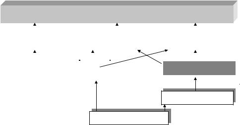
If the fuel cladding loses its integrity (i.e., if it fails), a key barrier to the release of fission products is breached, and the coolant in the RCS becomes contaminated with radioactive fission products released from the fuel. However, until the RCS remains intact, fission products are confined inside piping and do not enter the compartments. If the RCS piping ruptured, then the contaminated coolant would be released to the compartments (see Figure 2).
Environment
|
|
|
|
|
|
|
|
|
|
|
|
|
|
|
|
|
|
|
|
|
|
|
|
|
|
|
|
|
|
|
|
|
|
|
|
|
|
|
|
|
|
|
|
|
|
|
|
|
|
|
|
|
|
|
|
|
|
|
|
|
|
|
|
|
|
|
|
|
|
|
|
|
|
|
|
|
|
|
|
|
|
|
|
|
|
|
|
|
|
|
|
|
|
|
|
|
|
|
|
|
|
|
|
|
|
|
|
|
|
|
|
|
|
|
|
|
|
|
|
|
|
|
|
|
|
|
|
|
|
|
|
|
|
|
|
|
|
|
|
|
|
|
|
|
|
|
|
|
|
|
|
|
|
|
|
|
|
|
|
|
|
|
|
|
|
|
|
|
|
|
|
|
|
|
|
|
|
|
|
|
|
|
|
|
|
|
Other non leaktight compartments |
|
|
|
|
|
|
|
|
|
|
|
|
ALS |
|
|
|
|
|
|
|
|
|
|
|
Reactor building |
|
|
|||||||||||||||||||||||||||||||||
|
|
|
|
|
|
|
|
|
|
|
|
|
|
|
|
|
|
|
|
|
|
|
|
|
|
||||||||||||||||||||||||||||||||||||
|
|
|
|
|
|
|
|
|
|
|
|
|
|
|
|
|
|||||||||||||||||||||||||||||||||||||||||||||
|
|
|
|
|
|
|
|
|
|
|
|
|
|
|
|
|
|||||||||||||||||||||||||||||||||||||||||||||
|
|
|
|
|
|
|
|
|
|
|
|
|
|
|
|
|
|
|
|
|
|
|
|
|
|
|
|
|
|
|
|
|
|
|
|
|
|
|
|
|
|
|
|
|
|
|
|
|
|
|
|
|
|
|
|
|
|
|
|
|
|
|
|
|
|
|
|
|
|
|
|
|
|
|
|
|
|
|
|
|
|
|
|
|
|
|
|
|
|
|
|
|
|
|
|
|
|
|
|
|
|
|
|
|
|
|
|
|
|
|
|
|
|
|
|
|
|
|
|
|
|
|
|
|
|
|
|
|
|
|
|
|
|
|
|
|
|
|
|
|
|
|
|
|
|
|
|
|
|
|
|
|
|
|
|
|
|
|
|
|
|
|
|
|
|
|
|
|
|
|
|
|
|
|
|
|
|
|
|
|
|
|
|
|
|
|
|
|
|
|
|
|
|
|
|
|
|
|
|
|
|
|
|
|
|
|
|
|
|
|
|
|
|
|
|
|
|
|
|
|
|
|
|
|
|
|
|
|
|
|
|
|
|
|
|
|
|
|
|
|
|
|
|
|
|
|
|
|
|
RCS Piping |
|
|
|
|
|
|
|
|
|
|
|
|
|
Confinement |
|
|
|
|
|
|
|
|
|
|
|
Reactor Cavity |
|
|
|||||||||||||||||||||||||||||||
|
|
|
|
|
|
|
|
|
|
|
|
|
|
|
|
|
|
|
|
|
|
|
|
|
|
|
|
||||||||||||||||||||||||||||||||||
|
|
|
|
|
|
|
|
|
|
|
|
|
|
|
|
|
|
|
|
|
|
|
|
|
|
|
|
||||||||||||||||||||||||||||||||||
|
|
|
|
|
|
|
|
|
|
|
|
|
|
|
|
|
|
|
|
|
|
|
|
|
|
|
|
|
|
|
|
|
|
|
|
|
|
|
|
|
|
|
|
|
|
||||||||||||||||
|
|
|
|
|
|
|
|
|
|
|
|
|
|
|
|
|
|
|
|
|
|
|
|
|
|
|
|
|
|
|
|
|
|
|
|||||||||||||||||||||||||||
|
|
|
|
|
|
|
|
|
|
|
|
|
|
|
|
|
|
|
|
|
|
|
|
|
|
|
|
|
|
|
|
|
|
|
|
|
|
|
|
|
|
|
|
|
|
|
|
|
|
|
|
|
|
|
|
|
|
|
|
|
|
Fuel Channel
Fuel Cladding
Fig. 2. Flow paths of radioactivity release in RBMK-1500
According to its function and location, the fuel channel of RBMK reactor corresponds to the pressure vessel of vessel-type reactors. Therefore, it is the most important part of RCS. If the Fuel Channel (FC) wall heats up while the internal pressure is elevated, it may expand until it contacts the surrounding graphite blocks [4]. In the RBMK reactor, the deformation of fuel channels is arrested at rather modest uniform strain values due to the contact of the deformed FC with surrounding graphite block. Experiments show that the contacted channel fails only if and when the graphite block is disrupted by the pressure load transmitted to it by the deformed channel. At nominal pressure in FC (7 – 8 MPa) the temperature of fuel channel failure is not less than 650 °C and it depends on the heat-up rate. Experiments showed that in case of a higher heat-up rate, when the FC rupture occurs, the temperature values are higher compared to the lower heat-up rate. It was also discovered that in order to obtain the corresponding deformations at lower pressures higher temperatures or higher heat-up rates are required [4]. The acceptance criterion of 650 oC for fuel channel walls was assumed for the safety analysis [2, 3].
Deterministic Analysis of Beyond Design Basis Accidents in RBMK Reactors |
43 |
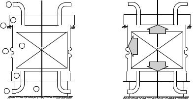
The fuel channels together with graphite stack are placed inside the leaktight reactor cavity, which is formed by a cylindrical metal structure together with bottom and top metal plates (Figure 3). If FC ruptured, the steamwater mixture would be released to this cavity and come into contact with hot surfaces of the graphite stack (Figure 4). The Reactor Cavity (RC) performs the function of containment; therefore, the integrity of the cavity is of high importance. RC consists of the structures shown schematically on the left side of Figure 3, which summarizes the design pressures based on the most conservative assessments. The figure indicates that the minimum of permissible excess pressures is 214 kPa [3] i.e. the pressure, which corresponds to the weight of upper metal plate (2). According to the reports [5, 6, 7], the more realistic values are: 1) for the upper plate 300 kPa; 2) for the casing (5) 330 kPa and lower plate (6) 380 kPa. Thus, in any case the top metal plate is the weakest point in the structure of reactor cavity, but the excess pressure that could be withstood is at least 300 kPa. The failure of the bottom plate could be expected only in the case of lowpressure accident scenario if the molten fuel would accumulate on it. In such accident scenario the fuel would relocate downwards in the fuel channel boundaries by candling (melting, forming eutectics with the clad and structure, flow downwards, freezing, and then remelting) until it reaches the pipes below RC. Since these pipes become unrestrained if they melt, the molten material would flow out onto the surrounding floor. Thus, the fuel is not expected to accumulate on the bottom plate of RC.
|
1 |
|
|
2 |
|
3 |
|
|
|
|
214 kPa |
|
4 |
kPa |
|
255 |
|
5 |
|
|
|
|
294 kPa |
|
6 |
|
7
8
Fig. 3. Reactor cavity components and limit pressures [7]: 1 – upper Reactor Cavity Venting System (RCVS) pipes, 2 – upper plate, 3 – roller support, 4 – reactor core, 5 – casing, 6 – lower plate, 7 – support, 8 – lower RCVS pipes
At NPP with a full-scope containment, which covers all the piping of reactor cooling system, the coolant would be discharged to the containment, i.e. reinforced and leaktight building capable to withstand excess pressure of 500 – 700 kPa. At Ignalina NPP with the RBMK-1500 reactor, a part of RCS above the reactor core is located outside the reinforced compartments. The drum separators and part of downcomers are contained in the DS compartments, whish are connected to the reactor hall (see XI and XII in Figure 4). These compartments are called “reactor buildings” and they can withstand 24.5 kPa excessive pressure, that is a few times lower inside pressure than in the reinforced leaktight compartments I, II, III, IV, V and VI
44 |
Nuclear Power Plants |
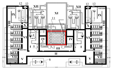
(see Figure 4). The compartments of the main RCS components (I) and corridor (II) can withstand 300 kPa, under-reactor compartments (III) and compartments of GDH and LWP (IV) – 80 kPa, bottom steam reception chambers (V) and vertical steam distribution shafts – 100 kPa of excessive pressure.
XIII
Fig. 4. RCS and Confinement of RBMK-1500: 1 – Fuel channel, 2 - Main Circulation Pump (MCP), 3 – Suction header, 4 – Pressure header, 5 – Group distribution header, 6 – Emergency Core Cooling System (ECCS) header, 7 – condensing pools, 8 – Condenser tray cooling system, 9 – Air release section, 10 – Steam release through main safety valve, 11 – Pipe of reactor cavity venting system, 12 – blow-down hatches, 13 – tip-up hatches. Compartments: I – Compartments of main RCS components (MCP, suction header, pressure header and downcomers), II – Corridor, III – Under-reactor compartment, IV – Compartments of Group Distribution Headers (GDHs) and Low Water Pipes (LWP), V – Bottom steam reception chambers, VI – Vertical steam distribution shafts, VII – Hot condensate chamber, VIII – Air venting channel, IX – Gas delay chamber, X – Top steam reception chambers, XI – Reactor hall, XII – Drum separator compartments, XIII – Reactor cavity
In case of an accident, these compartments have installed special valves or hatches that open to release the steam gas mixture to the environment. The part of steamlines and feedwater lines are contained in the turbine hall and deaerators compartments, respectively. If the rupture appears in these compartments then the release is not confined and the retention of fission products depends only on the natural sedimentation processes.
The ALS, RC and the other reactor buildings (DS compartments and reactor hall) of Ignalina NPP perform a function of containment, i.e. they are reinforced and leaktight, but due to its specifics it is usually called confinement. Therefore, in this chapter the term containment will be understood as a function rather than building.