

NUCLEAR POWER PLANTS
.pdfDeterministic Analysis of Beyond Design Basis Accidents in RBMK Reactors |
45 |
3. Categorization of the beyond design basis accidents for RBMK reactors
Based on the presented specifics of RBMK, two categories of Beyond Design Basis Accidents (BDBA), i.e. core damage types in RBMK reactors were proposed by RBMK designers from Russia (Kurchatov Institute and Research and Development Institute of Power Engineering) [8]:
damage of the core or its components with the reactor maintaining its overall structural integrity;
total damage of the core, resulting in the loss of general structural integrity of the reactor system.
Such grouping of accident is very important regarding accident management. If the core or its components remain structurally intact (first category of core damage), then the controlling actions (accident management) for limiting and delaying damage of the core, as well as prevention of confinement damage and mitigation of fission products release are possible. If the general structural integrity of the reactor system is lost, then depending on the degree to which the general structural integrity of the reactor is maintained, (second category of core damage), the emergency plan has to be activated in order to protect the public (sheltering, evacuation, etc.).
The first category of core damage can be further subdivided into the following accident groups (Fig. 5):
no severe damage of the core (1.1);
severe core damage accompanied by containment of the core fragments in the reactor core, accident localization system or other reactor buildings (1.2).
Accidents, leading to a complete reactor core damage, with loss of structural integrity of the reactor can also be divided into two groups [9]:
accidents when heat-up of the reactor core occurs during reactor operation or within the first seconds after the reactor shutdown, when decay heat is high (2.1);
accidents when heat-up of the reactor core occurs after the reactor shutdown (2.2).
|
Damage of the core or its components with |
|
Total damage of the core resulting in the |
|
|||||
|
the reactor maintaining its overall |
|
loss of the general structural integrity of |
|
|||||
|
|
structural integrity |
|
the reactor system |
|
||||
|
|
|
|
|
|
|
|
|
|
|
|
|
|
|
|
|
|||
No severe damage of the core |
|
|
Accident when reactor heat- |
|
|||||
(1.1) |
|
|
|
up occurs during reactor |
|
||||
|
|
|
|
|
|
operation (2.1) |
|
||
|
|
|
|
|
|
|
|
|
|
|
|
|
|
|
|
|
|
||
|
|
Severe core damage |
|
|
Accident when reactor heat- |
||||
|
|
accompanied by containment |
|
|
up occurs after reactor scram |
||||
|
|
of the core fragments in RC or |
|
|
(2.2) |
|
|||
|
|
ALS (1.2) |
|
|
|
|
|
||
|
|
|
|
|
|
|
|
|
|
Fig. 5. Categories of core damage types in case of BDBA in RBMK [9]
46 |
Nuclear Power Plants |
As it was mentioned, such grouping of accidents is the starting point for the development of the measures for accident management. However, the development of accident management guidelines requires performing deterministic analysis of all possible accidents in each group. Based on this analysis the accident consequences, available time for possible operator actions and possible modifications of emergency systems may be determined.
In the next chapter the deterministic analysis of reactor core and reactor cooling system is presented, whereas the modeling of the process in the RBMK confinement is presented in the monograph [10].
4. Models for the deterministic analysis of BDBA
Models developed for the thermal-hydraulic analysis of processes in the reactor core and reactor cooling system are presented below. The models of RBMK-1500 are developed using system state-of-the-art code RELAP5 and RELAP/SCDAPSIM.
4.1 Reactor cooling system model of RBMK-1500
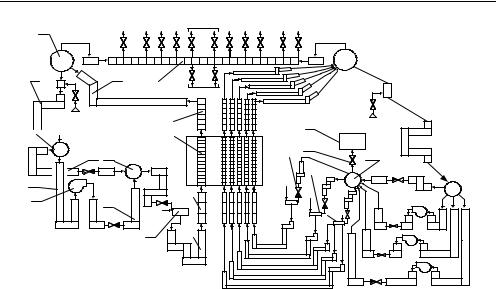
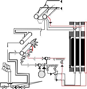
The RELAP5 computer code has been developed by Idaho National Engineering Laboratory [11]. It is a one-dimensional non-equilibrium two-phase thermal-hydraulic system code. The RELAP5 code has been successfully applied to PWR and BWR reactors. Since 1993 The RELAP5 model of the Ignalina NPP was used in the Lithuanian Energy Institute for the analyses of thermal-hydraulic response of the plant to various transients. The RELAP5/MOD3.2 model of the Ignalina plant (nodalization scheme) is presented in Figure 6.
The model consists of two loops. The left loop of RCS model consists of one equivalent core pass. Two drum separators are modeled as one “branch” type element (1). All downcomers are represented by a single equivalent pipe (2), further subdivided into a number of control volumes. The pump suction header (3) and the pump pressure header (8) are represented as branch objects. Three operating MCPs are represented by one equivalent element (5) with check and throttling-regulating valves. The stand-by MCP is not modeled. The bypass pipes
(7) between the pump suction header and the pump pressure header is modeled with the manual valves closed. This is in agreement with a modification recently performed at the Ignalina NPP. All FCs of this left core pass are represented by an equivalent channel (12) operating at average power and coolant flow.
Compared to the model for the left loop, in the right one, the loop section between the pressure header and the DS is represented in a more detailed manner. The MCP system is modelled in more detail also (it is modelled with three equivalent pumps). The right loop model consists of three equivalent core passes. First core pass represents one single GDH with an equivalent FC of average power. Second core pass represents single GDH with failed to close check valve. A few equivalent channels of different power levels represent fuel channels, connected to this GDH. The other core pass represents the other 18 GDHs. The channels of this pass are simulated by an equivalent FC of average power. The steam separated in the separators is directed to the turbines via steam pipes (15). Two Turbine Control Valves (TCVs) organize steam supply to the turbines. The guillotine break of MCP pressure header (17) in the right loop model of RCS is modelled by a valve (18). The flow area of this valve is double of pressure header flow area. The valve (18) is connected to the volume (19), which represents the compartments covered by RCS pipelines.
Deterministic Analysis of Beyond Design Basis Accidents in RBMK Reactors |
47 |
||||
|
1 |
Steam discharge devices TCV |
Steam discharge devices |
|
|
|
|
|
|
|
|
2 |
|
14 |
15 |
|
|
|
|
|
SDV-C |
|
|
|
|
|
Feedwater |
13 |
||
3 |
|
|
|
|
|
12 |
|
|
|
|
|
||
|
|
|
|
|
|
|
7 |
8 |
4 |
|
5 |
6 |
|
Reactor
|
11 |
ECCS |
|
9 |
10 |
|
21 |
Feedwater |
|
|
|
||
16 |
20 |
19 |
|
|
|||
|
|
||
E |
17 |
|
|
C |
E |
E |
|
C |
|||
C |
|||
S |
C |
||
C |
|||
|
C |
||
|
S |
||
|
18 S |
||
|
|
Fig. 6. RBMK-1500 model nodalization scheme: 1 - DS, 2 - downcomers, 3 - MCP suction header, 4 - MCP suction piping, 5 - MCPs, 6 - MCP discharge piping, 7 - bypass pipes, 8 - MCP pressure header, 9 - GDHs, 10 - lower water pipes, 11 - reactor core inlet piping, 12 - reactor core piping, 13 - reactor core outlet piping, 14 - steam-water pipes, 15 - steam pipes, 16 - check valve, 17 – single GDH, 18 – single GDH with failed to close check valve, 19 - ruptured pressure header, 20 - valve for break modeling, 21 – model of compartments, which surround the RCS pipelines
The fuel assemblies in reactor core are described as heat structure elements. The fuel channels with fuel assemblies were divided into a few (depending on the needs of modeling) equivalent groups according to the power and coolant flow rate values. For the core power of 4200 MW, the channel average power is assumed to be 2.53 MW, the maximum channel power is 3.75 MW and minimum channel power is 0.88 MW. It was assumed that approximately 95% of generated fission and decay power is generated in the fuel, and 5% in the graphite stack. More detail about the Ignalina NPP model, developed using RELAP5 code, is presented in [12, 13]. Model validation is performed by comparing calculation results and measurements using separate effect tests [14] and measurements at Ignalina NPP (integrate effects measurements) [13]. The experience of use of computer code for modeling of reactor cooling circuit in RBMK showed, that RELAP5 is very suitable for this task. One dimensional code is perfect for the modeling of thermal hydraulic and heat transfer processes in the RCS, which consists of many long pipelines without any cross flow.
For the analysis of processes, which occur in the reactor core (fuel channels of RBMK type reactors) at significant overheating of fuel assemblies up to fuel melting, specific computer tool for the analysis of processes during severe accident analysis should be used. For our purposes we used RELAP/SCDAPSIM code [15] that is an integrated, mechanistic computer code, which models the progression of severe accidents in light-water-reactor nuclear power
48 |
Nuclear Power Plants |
plants. The entire spectrum of in-vessel severe accident phenomena, including reactor- coolant-system thermal-hydraulic response, core heat up, degradation and relocation, and lower-head thermal loads, is treated in this code in a unified framework for both boiling water reactors and pressurized water reactors. Unfortunately, the RELAP/SCDAPSIM code has some limitations, related to the application for RBMK-type reactors:
SCDAPSIM gives a possibility to define PWR or BWR fuel bundles with a user-defined fuel enrichment, but does not give a possibility to include a plant specific core content (fuel with burnable erbium absorber, which is used in RBMK-1500);
RELAP/SCDAPSIM code does not include transport of fission products from fuel through the RCS piping and their release to confinement;
Heat generation is defined only once for all heat structures, i.e. fuel rod, fuel channel, graphite and Control & Protection System (CPS) channels. Therefore, the consideration of heat removal by CPS channels is very complicated.
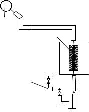
These limitations of RELAP/SCDAPSIM code were taken into account in modelling of BDBA in RBMK reactors: (1) the BWR fuel rod type was used for the modeling of RBMK fuel rods, (2) the transportation of fission products from fuel through cooling circuit was not evaluated because code limitation, (3) in order to avoid the troubles with the modeling of heat transfer from one fuel channel to another through graphite columns in radial direction in the core – the single channel model was used. Such model is acceptable for a rough analysis. The nodalization scheme of such model is presented in Figure 7. In order to perform the analysis, the following boundary conditions should be assumed for the model elements, modeled as time dependent volumes and junctions:
pressure and water temperature in the group distribution header (3);
pressure in the drum separators (1);
coolant flow rate through the fuel channel with average power (2).
This model is described in more detail in the papers [16, 17] and the monograph [18].
1
2
Reactor cavity
3
Fig. 7. Nodalization scheme of a simplified RBMK-1500 model (single fuel channel): 1 – drum separator and steam lines, 2 – fuel channel, 3 – GDH
Deterministic Analysis of Beyond Design Basis Accidents in RBMK Reactors |
49 |
5. Deterministic analysis of BDBA in RBMK-1500
5.1 Analysis of accidents with no severe damage of the core
As it was mentioned, the first category of BDBA (damage of the core or its components with the reactor maintaining its overall structural integrity see Figure 5) is divided into two groups: (1.1) no severe damage of the core; (1.2) severe core damage accompanied by the containment of core fragments in the reactor core, accident localization system or other reactor buildings.
The examples of accidents for RBMK-1500 in the first group (1.1, see Figure 5) are the failure of the final heat sink systems with the loss of their functions or staff error, failure of group of reactor Control & Protection System (CPS) rods, failure of one or more channels in the reactor Emergency Core Cooling System (ECCS) short-term or long-term subsystems, failure of the system which supplies feedwater during a prolonged period of time, and other failures. This group of accidents involves additional failures of the equipment in the safety systems (additional to failures considered by the single failure principle). Usually the accidents of first group (no severe damage of the core) are analyzed in order to justify the effectiveness of the functional backup, as well as to assess the conditions and the time available for the backup systems to be actuated. As a rule, this belongs to the field of the accident management on the basis of symptom-oriented emergency operating procedures.
Thus, in case of a postulated failure of CPS rods movement during reactor operation at power, the actions taken by the operators to shutdown the reactor and to hold it in a subcritical state were determined. The reactor can be shutdown and maintained subcritical by inserting one CPS rod into the core, decreasing the water temperature in the CPS cooling circuit or decreasing the temperature of the graphite stack [8]. At Ignalina NPP the Additional Hold-down System is implemented in case of CPS malfunction to prevent reactor re-criticality by injecting the liquid poison (Gadolinium Nitrate) into the CPS cooling circuit [19].
During reactivity initiated accidents the situation can occur when the group of control rods is withdrawn erroneously. Under adverse conditions it is possible that the signal for local Automatic control will not be generated and the local power increase can occur in a group of fuel channels. Validated calculations using the experimental data showed that this increase could reach 2-2.5 times of the nominal channel power, but it does not cause significant coolant flow decrease in the fuel channels (due to the increased channel resistance in the steam zone) and overheating of the fuel channels [9]. Since this chapter mainly deals with the thermal-hydraulics, more detailed examples with reactivity initiated accidents are not presented there.
Another example could be the loss of long-term cooling. The performed deterministic calculations showed that the reactor core cannot be damaged without the make-up by feedwater during any transient after full reactor shutdown in approximately 1.5 hours [8, 20]. One high pressure pump is sufficient to cool down the reactor for one hour after the reactor shutdown. If the water supply from one pump is re-established, all the parameters of RCS and reactor remain within safe operation limits. However, if the high pressure pumps are not available, the manual operators’ actions are required. In [18] the optimal reactor core cooldown scenario for RBMK-1500 in case of station blackout was developed (see Figure 8 - Figure 10). The modeling of such scenario was performed using RELAP5 model presented in Figure 6.
50 |
Nuclear Power Plants |
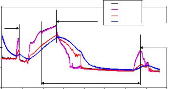
In the analysis presented below, it is considered that the operator takes early actions: 15 minutes after the beginning of the accident the operator begins to supply cold water from ECCS hydro-accumulators into GDH of both RCS loops. After approximately 1.5 hours from the beginning of the accident, the peak fuel cladding temperature exceeds 400 oC (Figure 8). According this signal, the operator opens one steam relief valve to decrease pressure in RCS (Figure 9). At the same time the operator takes actions to maintain the water supply by gravity from deaerators and prepares the connection for water supply from the artesian water source. The activation of ECCS hydro-accumulators after 15 minutes from the beginning of the accident provides only a small amount of water due to equalization of pressures in hydro-accumulators and GDH. Additional amount of water from hydroaccumulators is injected when the pressure in RCS decreases (~2 h after the beginning of the accident). The water supply from ECCS hydro-accumulators and opening of one steam relief valve would result in the increase of water level in RCS (Figure 10). At the time moment t = 2.5 h, the water supply from ECCS hydro-accumulators stops. Approximately 170 m3 of water is injected from ECCS hydro-accumulators.
|
800 |
|
|
|
|
|
fuel |
|
|
|
|
|
|
2 SRVs are |
|
cladding |
|
|
|
|
|
Opening |
|
|
|
|
|
||
|
|
|
|
|
FC wall |
|
|
||
|
|
of 1 |
|
|
opened |
|
|
|
|
|
|
|
|
|
graphite |
|
|
||
|
600 |
SRV |
|
|
|
|
Start of vater |
||
|
|
|
|
|
|
||||
C |
|
|
|
|
|
|
|
supply from |
|
o |
|
|
|
|
|
|
|
artesian water |
|
Temperature, |
|
|
|
|
|
|
|
||
400 |
|
|
|
|
|
|
source |
|
|
|
|
|
|
|
|
|
|
||
|
|
|
|
|
|
|
|
|
|
|
200 |
|
|
|
|
|
|
|
|
|
|
|
|
|
Water supply from deaerators |
|
|
|
|
|
0 |
|
|
|
|
|
|
|
|
|
0 |
2 |
4 |
6 |
8 |
10 |
12 |
14 |
16 |
|
|
|
|
|
Time, h |
|
|
|
|
Fig. 8. RCS de-pressurization and water supply into reactor from ECCS hydro-accumulators, deaerators and artesian water source in case of station blackout. Temperatures of fuel, fuel rod cladding, fuel channel and graphite
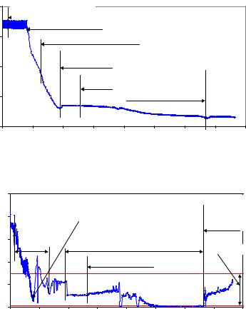
When the pressure in RCS decreases down to 1.2 MPa (pressure in deaerators), the water flow from the deaerators begins (t = 3.8 h). There are four deaerators, which contain 480 m3 of water with temperature of ~ 190 oC. After the connection of deaerators to RCS, the pressure decrease leads to boiling of water in deaerators. The initial flow rate of water from deaerators does not warrant adequate cooling of the core – the temperature of core components is increasing at the time interval t = 3 – 5 h (Figure 8). To increase the flow rate of water from deaerators, at the time moment t = 5.3 h the operator opens one additional Steam Relief Valve (SRV). As it is seen from Figure 8, this action improves the core cooling conditions and the temperature of core components starts to decrease. The pressure in RCS decreases down to the pressure in artesian water system (~ 0.6 MPa) only more than 13 hours after the beginning of the accident. A complete connection of artesian water to RCS is permitted only after the decrease of pressure in RCS down to the level of pressure in the
Deterministic Analysis of Beyond Design Basis Accidents in RBMK Reactors |
51 |
artesian water source. These measures should prohibit the injection of coolant from RCS into the pipeline of artesian water. After the connection of artesian water source to supply water into reactor, the water level in reactor core starts to increase, which means the success of core cooling. The mentioned operators’ actions lead to a slow decrease of pressure in RCS, the fuel rods claddings and channels walls temperatures become not higher than 600 oC.
Pressure, MPa
8 |
Start of vater supply from |
|
|
|
|
|
|
|
|
ECCS hydroaccumulators |
|
|
|
|
|
|
|
|
|
Opening of 1 SRV |
|
|
|
|
|
|
6 |
|
ECCS hydroaccumulators are empty |
|
|
|
|||
|
|
Start of vater supply |
|
|
|
|
||
4 |
|
from deaerators |
|
|
|
|
|
|
|
|
|
|
|
|
|
|
|
|
|
|
2 SRVs are |
|
Deaerators are empty. |
|
|
|
|
|
|
opened |
|
|
|
||
|
|
|
|
Start of vater supply from |
|
|
||
|
|
|
|
|
|
|
||
2 |
|
|
|
|
artesian water source |
|
|
|
0 |
|
|
|
|
|
|
|
|
0 |
2 |
4 |
6 |
8 |
10 |
12 |
14 |
16 |
|
|
|
|
Time, h |
|
|
|
|
Fig. 9. RCS de-pressurization and water supply into reactor from ECCS hydro-accumulators, deaerators and artesian water source in case of station blackout. Pressure behavior in RCS
|
25 |
|
|
|
|
|
|
Start of vater |
|
|
|
|
|
|
|
|
|
||
|
20 |
Water supply |
|
Opening of 1 SRV |
|
|
supply from |
|
|
|
|
|
|
artesian water |
|||||
m. |
|
from ECCS |
|
|
|
|
|
source |
|
15 |
hydro- |
|
|
|
|
|
|
|
|
level, |
accumulators |
|
Water supply from deaerators |
|
|
|
|||
|
|
|
Core region |
|
|||||
|
|
|
|
|
|
|
|
||
Water |
10 |
|
|
2 SRVs are opened |
|
|
|
|
|
|
|
|
|
|
|
|
|
|
|
|
5 |
|
|
|
|
|
|
|
|
|
0 |
|
|
|
|
|
|
|
|
|
0 |
2 |
4 |
6 |
8 |
10 |
12 |
14 |
16 |
|
|
|
|
|
Time, h |
|
|
|
|
Fig. 10. RCS de-pressurization and water supply into reactor from ECCS hydroaccumulators, deaerators and artesian water source in case of station blackout. Calculated water level behavior in RCS
The results of the mentioned neutron-physical and thermal-hydraulic investigations have served as the basis for expanding the region where the accidents of the first group with multiple failures can be controlled using the symptom-oriented emergency operating procedures, and they have made it possible to determine the actions to be taken by personnel in order to prevent severe core damage.
52 |
Nuclear Power Plants |
5.2 Analysis of accidents leading to severe core damage accompanied by containment of core fragments in the RC, ALS or other reactor buildings
Accidents in the second group (1.2, see Figure 5) are analysed in order to develop the measures to preserve the structural integrity of the reactor or to determine the required means and time available for subsequent cooling of the reactor core. The accidents of this group are conventional severe accidents with core meltdown as a result of misbalance between energy source and heat sink. The development of such accidents in RBMK has much in common with overheating processes of vessel-type reactors, but it differs by the RBMK features mentioned above.
The heating and melting of a RBMK core can potentially occur as a result of misbalance between heat generated in the core and removed by reactor cooling system and emergency core cooling systems. A typical example of such accident is the damage of the boundaries of the circulation loop (LOCA type accident), accompanied by the failure of the ECCS or additional loss of feedwater.
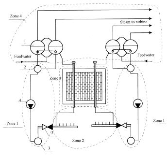
The LOCAs, according the PSA terminology for RBMK-1500, were categorized according to the rupture size and location in the RCS. A large LOCA means a rupture of the biggest diameter pipes in RCS, i.e. pipes with diameter of 300 – 1000 mm. Medium LOCA is a rupture of pipes with diameter of 100 – 300 mm, whereas small and very small LOCA signifies a rupture of pipes with diameters of 50 – 100 mm and 30 – 50 mm respectively. The location of LOCAs in the RCS is groped into 4 zones (see Figure 11).
Fig. 11. Distribution of the zones in the RCS: 1 – DS, 2 – MCP suction header, 3 - MCP pressure header, 4 – MCP, 5 – check valve
Deterministic Analysis of Beyond Design Basis Accidents in RBMK Reactors |
53 |
Pipelines located in Zone 1 have large diameters: ~1000 mm – the main circulation pumps pressure and suction headers, ~600 mm – MCP connecting pipelines and ~300 mm – group distribution header piping. Therefore, large and medium LOCAs are possible in this zone. Pipelines located in Zone 2 have smaller diameter than the ones in Zone 1: ~300 mm – GDH piping and ~50 mm – lower water piping. Piping of Zone 4 (outside ALS compartments) consists of a part of downcomers (~600 mm diameter), feedwater lines of 500 mm diameter and steamlines of 600 mm diameter. Fuel channel break in the reactor cavity (LOCA in Zone 3) is a separate type of accident. The analysis of LOCAs in Zones 1, 2 and 4 was performed using RELAP5 model, presented in Figure 6.
5.2.1 LOCA in Zone 1
In case of break in Zone 1, a huge amount of coolant used for the reactor core cooling is discharged through the break. Consequently, the reactor core cooling is extremely worsened or terminated at all in the group of the fuel channels. GDH check valve prevent coolant water leaking from the core in the opposite direction. Depending on the location of the break, the cooling of FCs connected to one group distribution header (in the case of GDH break) or in all channels of one RCS loop (in the case of MCP pressure or suction header break) can be lost. The emergency protection (reactor shutdown) is activated within the first seconds due to the pressure increase in the reinforced leaktight compartments. Cooling of the reactor core is restored after the activation of ECCS. After 2
– 3 seconds the short-term subsystem of ECCS (two trains of hydro accumulators and one train from the main feedwater pumps) is activated. This subsystem starts to supply water into GDH downstream check valve and is designed to cool down the reactor within the first 10 minutes. Later the long-term subsystem of ECCS, which consists of 6 ECCS pumps and 6 auxiliary feedwater pumps, is activated. The long-term subsystem of ECCS supplies the water to both loops of RCS. The fuel cladding and fuel channel wall temperatures start to decrease after the ECCS activation.
In the case of large LOCA in Zone 1, the pressure upstream fuel channels decreases very fast. To prevent the reverse of coolant flow in the channels, the check valves are installed in each GDH. The failure of some of these valves effects the cooling conditions of channels connected to the affected GDH and may change the consequences of the accident. For example, in the case of the MCP pressure header break, the channels connected to the GDH with failed to close check valve are cooled by the reverse coolant flow from the drum separators (Figure 12). At the beginning of the accident, these FCs are cooled by the saturated water flow, but later (after DSs get empty) only by the saturated steam. Due to the worsened cooling conditions, fuel cladding temperatures in the channels connected to GDH with failed to close check valve increases higher than in the other channels of the affected RCS loop.
The feature of LOCA type accidents in Zone 1 is the heat-up of the fuel in the affected RCS loop during the first seconds of the accidents. It should be noted that the first fuel cladding temperature increase asserts only at the very beginning of the accident and takes a very short time: no more than 30 seconds. In the case of the MCP pressure header break with additional failures of short-term subsystem of ECCS, a short-term violation of an acceptance criterion for fuel rods cladding of 700 oС is observed in a considerable group of channels. Such increase of temperatures is related with stagnation of coolant flow rate after the GDHs
54 |
Nuclear Power Plants |
check valves closing. This stagnation is terminated with the start of ECCS water supply. If the loss of the preferred AC power of the Unit does not occur simultaneously, so the stagnation is terminated after 10 s from the start of water supply from ECCS pumps. The excess of acceptance criteria for fuel rod cladding of 700 oС is probable in FCs, initial power of which is higher than 2.5 MW (see Figure 13). There are 370 of such FCs in the affected RCS loop (see Figure 14). If the loss of preferred AC power takes place simultaneously, the stagnation is prolonged (ECCS pumps are started after the start of diesel generators). In this case the acceptance criterion for fuel rod cladding is violated in FCs which have the initial power higher than 2.0 MW. There are 670 of such FCs in the affected RCS loop (see Figure 14). However, the peak temperature of FCs walls is much below than the acceptance criterion for the FC wall (650 oС).

 6
6
2 


1
3
 4
4
5 |
7 |
|
|
8 |
|
Fig. 12. MCP pressure header rupture with GDH check valve failure: 1 – break of MCP pressure header; 2 – overflow of coolant from DS; 3 – MCP suction piping; 4 – coolant discharge from MCP pressure piping; 5 – ECCS water supply; 6 – steam supply from intact loop of the RCS; 7 – coolant supply into reactor core; 8 – maintenance valves
The detailed analysis was performed to evaluate the possibility of failure of those fuel rods where cladding temperature exceeds 700 oС. This analysis was performed using RELAP/SCDAPSIM model presented in Figure 7. The calculated pressure inside the fuel rods remains below pressure outside fuel (Figure 15). Thus, the ballooning of fuel rod claddings do not occur in the fuel channels with initial power less than 3.4 MW. The detailed analysis allows removing the surplus conservatism in the analysis (Figure 14).
Another fuel cladding temperature increase starts approximately 200 seconds after the beginning of the accident and is caused by the decrease of the reversed coolant flow, which in turn is due to the pressure decrease in DSs of the affected loop of RCS (Figure 12). A