

NUCLEAR POWER PLANTS
.pdfThe Gap Measurement Technology and Advanced RVI |
155 |
Installation Method for Construction Period Reduction of a PWR |
Fig. 26. Installation of a marking tool
4.1.6 Combination of the CSB assembly and the RV
1.The CSB assembly was aligned to the RV centerline and the CSB assembly was inserted in the RV. The CSB assembly was turned at 45° and was lowered to prevent damage to the DAK. It was then combined after the CSB assembly was turned to the original position before ensuring a 50 cm interval between the CSB assembly and the RV.
2.When the CSB assembly was installed, the load measured by a hydra-set was continuously checked. In addition, when the CSB assembly was at a height of approximately 30 cm from the RV head seating surface, the bottom surface (datum “B”) of the CSB upper flange was used to stop the descent of the CSB assembly. A basis surface (datum “B”) of the CSB upper flange was used for a parallel adjustment to within 0.381 mm of the RV head seating surface.
3.The load of the hydra-set was decreased to 10,000 lb and was checked given that the CSB came in contact with the RVI installation surface. The RV centerline and the CSB centerline were aligned within 0.0254 mm by CSB position devices (8 EA).
4.The vertical degree for the CSB keyway and the datum hole were measured and their relative positions on the CSB centerline were confirmed.
5.The gaps between the RV head seating surface and the upper surface of the CSB flange were measured in 45° intervals. The gaps (2.1336 – 2.9464 mm) of the RV outlet nozzle and the temperatures of the nozzle area were also measured.
6.The alignment of the RV/CSB centerline and the requirements of the nozzle gap were checked. If the requirements were not satisfied, it was necessary to repeat this procedure. If the position of the DAK changed before and after the installation of the CSB due to the checking of the position of the DAK, the measurements had to be done again and the existing checklist was invalidated. All installation requirements were met; the final adjustment conditions and the variation of the CSB centerline on the RV centerline were measured and recorded.
4.1.7 Length measurement using the remote measurement system
1.The channel box of the internal CSB and the air hose, compressor, electric power cord, power supply and signal cables of the external CSB were connected. Electric power was then supplied.
156 |
Nuclear Power Plants |
2.Using a software program running on a remote measurement computer, the length was measured a total of five times. The pressure for the measurement was adjusted to 0.8 ~ 1 bar; this was set to have a zero length to ensure that the data were entered correctly. The average value of the measured lengths was used as the data. Once the measurement was completed, the data were stored and the measured length was recorded.
3.After the gap measurements were completed, all electric power was turned off. After the RV and the CSB assembly were detached, the air hose, electric power cord and signal cable were respectively separated from the compressor, electric power, USB hub and RS-485 converter. Once separated, the air hose, electric power cord and signal cable were temporarily fixed in the CSB assembly to ensure that they would not interfere with the disassembly of the CSB assembly.
4.1.8 Separation of the CSB Assembly and RV
1.The CSB assembly was separated from the RV and set on a storage stand. The CSB assembly was lifted at 45° turns after vertical lifting of approximately 50 cm in order to prevent the DAKs from being damaged. The CSB assembly was checked continuously via a load measured by a hydra-set.
2.After the checked positions of the gauge blocks were marked using digital probes, the widths of the marked positions were measured. After removing the gauge blocks, the gaps between the CSB snubber lugs and the RV core-stabilizing lugs were used to calculated the processing dimensions of the snubber shims; the gaps were calculated at 0.381-0.508 mm as a permissible range.
4.1.9 Installation and measurement of the shim on the RV core-stabilizing lug
1.The dimensions of the refined shims were measured and a penetration test was conducted. Before installation of the shims, the RV core stabilizing lugs and the cap screws were checked to confirm the integrity of each screw. Neolube, a dry film lubricant, was applied twice to the threaded surfaces of the cap screws and bearing surface. Fig. 13 shows the assembly of the snubber shims on the RV core-stabilizing lug.
2.When the shims were installed, the cap screws were assembled by hand and tightened according to a three-step tightness method: 160, 213 and 266 ft-lbs. It was important that after the shims were installed, the upper gaps and lower gaps were maintained as constant (0.1016 mm).
3.After the shims were installed, their full widths were measured in six positions to measure the equal intervals. The DAKs were adjusted to vertical degrees at 0.0254 mm/ft for the RV head seating surface. At this point, the vertical degrees of the DAKs and the status of the installed positions were recorded.
4.According to section 2.6 “Combination of the CSB assembly and the RV,” the CSB assembly was installed in the RV. When the RV core-stablizing lugs and the RV snubber shims were connected, they were lowered using the hydra-set. The RV centerline and the CSB centerline were adjusted within 0.0254 mm using the DAKs, and the CSB assembly was completely lowered. If the positions of the DAKs changed, the measurements had to be done again.
5.The gaps between the RV and the CSB outlet nozzles were recorded and the offsets of the CSB keyways regarding the DAKs were recorded as well. The offsets of the CSB centerline in relation to the RV centerline were also calculated and recorded.

The Gap Measurement Technology and Advanced RVI |
157 |
Installation Method for Construction Period Reduction of a PWR |
6.The air hoses, electric power cords and signal cables of the remote measurement system were reconnected to the compressor, electric power, USB hub and RS-485 converter, and electric power was supplied. The length of the snubber shims was measured five times. Once the measurement was complete, the measured data were stored and the measured lengths were recorded. The measured lengths of the shims were confirmed to be within a permissible range (0.381 - 0.508 mm). If the measured lengths of the shims exceeded the permissible range, they would be used after reprocessing.
7.All electric power was turned off, and the air hoses, electric power cords, and signal cables were respectively separated from the compressor, electric power, USB hub and RS-485 converter. Separated air hoses, electric power cables and signal cables were temporarily fixed in the CSB assembly when the RV and CSB assembly were detached in order to avoid interference with cables and pieces of equipment. Finally, the gaps between the CSB and the RV core-stop lugs were measured.
4.1.10 Separation and confirmation of the remote measurement system
1.The CSB assembly was separated from the RV and set down on a storage stand. The channel boxes and digital probes, threaded connection jigs, air hoses, electric power cables, and signal cables were completely removed from the CSB assembly.
2.After removing the CSB assembly, snubber shims were confirmed in the combined state. All heads of the cap screws were dug with holes of Φ 3.0226 mm at a depth of 19.05 ± 0.762 mm.
3.All holes of the heads of the cap screws had pins inserted and their installation status was checked. Plugs (Φ 12.7 mm) installed to fix the pins were inserted; after welding the plugs, penetration tests were carried out.
4.2 Development of improved installation schedule for RVI modularization
Table 6 presents a comparison of the existing RVI installation process at the Shin-kori #1 nuclear power plant and the modularization installation process developed.
Compared with the existing method, it was found that the developed installation process using RVI modularization can shorten the installation period to about 67 days in the critical path. This can reduce the construction period, as follows: RV & CSB dimension check (15 days), CSB alignment & gap measurement (13 days), RV & CSB & LSS/CS alignment (13 days), flexure welding (20 days) and CSB assembly installation & alignment check (6 days).
The RV & CSB dimension check (15 days), flexure welding (20 days) and CSB assembly installation & alignment check (6 days) are conducted through a concurrent process before the determination of the critical path in the existing installation process. In addition, the CSB module alignment & gap measurement (13 days) and RV & CSB module alignment (13 days) are correspondingly reduced using the remote measurement system and the improved installation procedure.
Fig. 27 shows the existing RVI installation schedule in the critical path at the Shin-kori #1 nuclear power plant in Korea. It consists of the following steps: (1) the RV & CSB dimension check (2) the CSB alignment & gap measurement (3) snubber shim machining & installation
(4) the RV & CSB & LSS/CS alignment (5) flexure welding (6) the CSB assembly installation & alignment check and (7) the upper guide structure (UGS) & RV head installation & alignment check. Therefore, the RVI installation period at the Shin-kori #1 nuclear power plant should be required approximately 129 days in the critical path.
158 |
|
Nuclear Power Plants |
||
|
|
|
Unit. Day |
|
|
|
Existing Method |
Proposed Modularization Method |
|
|
|
(Ex. Shin-kori #1, Korea) |
|
|
|
|
|
|
|
|
|
|
|
|
|
RV & CSB Dimension Check |
15 |
- |
|
|
CSB Alignment & Gap Measurement |
18 |
CSB Module Alignment & Gap Measurement (5) |
|
|
Snubber Shim Machining & Installation |
21 |
21 |
|
|
RV & CSB & LSS/CS Alignment |
28 |
RV & CSB Module Alignement (15) |
|
|
Flexure Welding |
20 |
- |
|
|
CSB Assembly Installation & Alignment Check |
6 |
- |
|
|
UGS & RV Head Installation & Alignment Check |
21 |
21 |
|
Table 6. Comparison of existing RVI installation period and modularization installation period
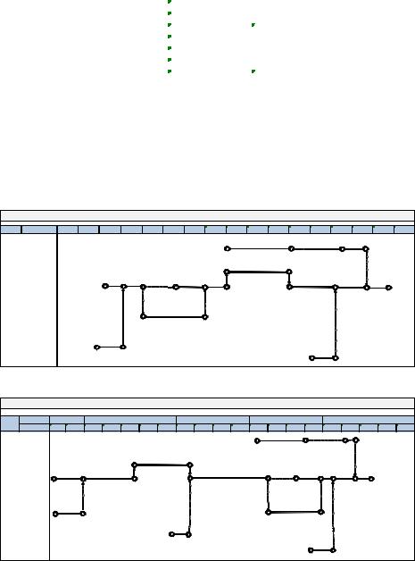
Fig. 28 shows the RVI modularization installation schedule. To use RVI modularization in an actual construction project, modularization installation schedule was developed. The RVI modularization schedule in the critical path consists of the following steps: (1) CSB module alignment & gap measurement (2) snubber shim machining & installation (3) RV & CSB module alignment (4) and UGS & RV head installation & alignment check. Therefore, it was determined that the RVI modularization installation period should require about 62 days in the critical path.
|
|
|
|
|
|
RVI Modularization Installation Schedule |
|
|
|
|
|
|
||||||||||
Unit |
Week |
|
|
|
|
|
|
|
|
|
1 |
2 |
3 |
4 |
5 |
|
6 |
7 |
8 |
9 |
10 |
|
|
RV Head |
|
|
|
|
|
|
|
|
|
Head Lifting Rig Assembly |
Clean & Calculation of Dimension |
||||||||||
|
|
|
|
|
|
|
|
|
|
|
|
|
|
|
|
|
|
|
|
|
||
|
|
|
|
|
|
|
|
|
|
|
Snubber Shim Machining & Installation (21) |
|
|
|
|
|||||||
|
|
|
|
|
|
|
|
|
|
|
|
|
|
|
|
|
UGS Installation |
|
|
|||
|
|
|
RV & CSB Dimension Check(15) |
|
|
|
|
|
|
|
|
|
& Alignment |
|
|
|
||||||
|
|
|
|
|
|
|
|
|
|
|
|
Check(12) |
|
|
|
|||||||
|
RV |
|
|
|
|
|
|
|
|
|
|
|
|
|
|
|
|
|
|
|
|
|
|
|
|
|
|
|
|
|
Installation & |
|
CSB Module Alignment |
|
RV & CSB Module |
|
RV Head |
|
|||||||
|
|
|
|
|
|
|
|
Welding |
|
|
& Gap Measurement(5) |
|
Alignement(15) |
|
|
|||||||
|
|
|
|
|
|
|
|
Flow Skirt |
|
|
|
|
|
|
|
|
|
Installation & |
|
|||
|
|
|
|
|
|
|
|
|
|
|
|
|
|
|
|
|
|
|
Alignment(9) |
|
||
|
CSB |
|
|
|
|
|
|
|
|
|
|
|
|
|
|
|
|
|
|
|
|
|
|
|
|
|
|
|
|
Flexure Welding(20) |
|
|
|
|
|
|
|
|
|
|
|
|
|||
LSS/CS Ass'y |
|
|
|
|
|
|
|
|
|
|
|
Clean & Calculation of |
|
|
|
|
||||||
|
UGS |
|
|
|
Clean & Calculation of |
|
|
|
|
|
Dimension |
|
|
|
|
|
|
|||||
|
|
|
|
Dimension |
|
|
|
|
|
|
|
|
|
|
|
|
|
|
|
|
||
|
|
|
|
|
|
|
|
|
|
|
|
|
|
|
|
|
|
|
|
|
||
Fig. 27. Existing RVI installation schedule |
|
|
|
|
|
|
|
|
|
|
|
|
||||||||||
|
|
|
|
|
|
|
Shin-kori #1 RVI Installtion Schedule |
|
|
|
|
|
|
|
|
|||||||
Unit |
Month |
Nov. 08 |
|
Dec. 2008 |
|
|
|
Jan. 2009 |
|
|
Feb. 2009 |
|
|
|
Mar. 2009 |
|
|
|||||
Week |
1 |
2 |
3 |
4 |
5 |
6 |
7 |
8 |
9 |
10 |
11 |
12 |
13 |
14 |
15 |
16 |
17 |
18 |
19 |
20 |
||
|
||||||||||||||||||||||
|
|
|
|
|
|
|
|
|
|
|
|
|
|
|
|
|
|
|
Clean & |
|
|
|
|
|
|
|
|
|
|
|
|
|
|
|
|
|
|
|
|
|
|
Calculation |
|
||
RV Head |
|
|
|
|
|
|
|
|
|
|
|
Head Lifting Rig Assembly |
|
|
of Dimension |
|
||||||
|
|
|
|
|
|
|
|
|
|
|
|
|
|
|
|
|||||||
|
|
|
|
|
Snubber Shim Machining & Installation(21) |
|
|
|
|
CSB Assembly |
|
RV Head |
|
|
||||||||
|
|
|
|
|
|
|
|
|
|
|
|
|
|
|
|
Installation & |
|
Installation & |
|
|||
|
|
RV & CSB Dimension Check(15) |
|
|
|
RV & CSB & LSS/CS Alignment(28) |
|
Alignment Check(6) |
Alignment(9) |
|
||||||||||||
|
|
|
|
|
|
|
|
|
|
|
|
|||||||||||
|
RV |
|
|
CSB Alignment & Gap |
|
|
|
|
|
|
|
|
Installation & |
|
UGS Installation & |
|
||||||
|
|
|
|
Measurement(18) |
|
|
|
|
|
|
|
|
|
|
|
|||||||
|
|
|
|
|
|
|
|
|
|
|
|
|
Welding |
|
|
Alignement Check(12) |
|
|||||
|
|
|
|
|
|
|
|
|
|
|
|
|
|
|
Flow Skirt |
|
|
|||||
|
|
|
|
|
|
|
|
|
|
|
|
|
|
|
|
|
|
|
|
|||
|
CSB |
|
|
|
|
|
|
|
|
|
|
|
|
|
|
|
|
|
|
|
|
|
|
|
Clean & Calculation of Dimension |
|
|
|
|
|
|
Flexure Welding(20) |
|
|
|
|
|
||||||||
LSS/CS Ass'y |
|
|
Clean & Calculation of Dimension |
UGS |
Clean & Calculation of Dimension |
|
Fig. 28. Developed RVI modularization installation schedule

The Gap Measurement Technology and Advanced RVI |
159 |
Installation Method for Construction Period Reduction of a PWR |
4.3 Results
An improved installation procedure and schedule for RVI modularization were developed. These developments facilitated a RV & CSB dimension check, flexure welding of the LSS and the CS in the CSB and a CSB assembly installation & alignment check before the main installation process. The new procedure and schedule also facilitated a CSB alignment & gap measurement and a RV & CSB module alignment, as undertaken during the main installation process.
According to the improved installation procedure for RVI modularization, the gaps between the RV core-stabilizing lug and the CSB snubber lug of the RVI mockup are measured by a remote measurement method. The results measured by these methods are analyzed with design shims attached to the assembly between the RV core-stabilizing lug and the CSB snubber lug. After the shims on the RV core-stabilizing lug were installed, The measured gap values satisfied the requirements within the permissible range, 0.381 – 0.508 mm, were found.
4.4. Conclusion
The development of an improved installation procedure and schedule is one of the most important technologies for RVI modularization. The improved installation procedure and schedule developed here can be used at nuclear power plant construction sites. The improved installation procedure through an experiment using a verified remote measurement system was validated and then manufactured mockup.
On the basis of these studies, technologies for RVI modularization using the improved installation procedure and schedule will be applied to the construction project.
5. Acknowledgements
Korea Hydro and Nuclear Power Co., Ltd. applied for international patents on all R&D results in this chapter.
6. References
ABB-CE, (1995). Support Work Agreement Work Order Delivery H-4, Korea Electric Power Corporation.
Ko, D. Y. & Bae, B. H. (2006). A Study on the EMC for Application of Wireless Communication System in Nuclear Power Plants. Conference on Information and Control System, Korea.
Ko, D. Y., Lee, J. G., Kang, Y. C., & Kim, S. H. (2009). Development of a measurement system of gap between CSB and RV to shorten a nuclear reactor installation period. Nuclear Engineering and Design 239, pp.(495-500).
Ko, D. Y. & Lee, J. G. (2010). Development of a Remote Measurement System for the gap between RV and CSB for RVI-modularization. Nuclear Engineering and Design 240, pp. (2912-2918).
Ko, D. Y. (2011). Development of an Improved Installation Procedure and Schedule of RVI Modularization for APR1400. Nuclear Engineering and Technology, Vol. 43 No. 1, pp.(89-98).
Korea Electric Power Research Institute. (1997). Construct Ability Improvement for Nuclear Power Plants, TR-95ZJ02-97-41.
160 |
Nuclear Power Plants |
Korea Hydro & Nuclear Power Company. (2002). Construction Study Report for Development of Next Generation Reactor, TR.A99NJ13.P2002.Shin2, pp. 633-672.
Korea Hydro & Nuclear Power Company. (2009). The Development of Modularization Technology for Reactor Internals, TR-S05NJ02-J2009-58, pp. 26-135.
Rechard S. Figliola & Donald E. Beasley. (2000). Theory and Design for Mechanical Measurements, Wiley, pp.(575-580).
Solartron-metrology. (2006). Digital technology digital probes, Solartron-metrology.
Tomas G. Beckwith, Roy D. Marangoni & John H. Lienhard. (1993). Mechanical Measurement, Addison-Wesley Publishing Company, pp.(515-520).
6
Strategic Environmental Considerations
of Nuclear Power
Branko Kontić
Jožef Stefan Institute
Slovenia
1. Introduction
The key topics of this chapter are i) comparative evaluation of various energy options, and ii) radioactive waste disposal. Both are treated from the strategic planning and assessment points of view and are supported by a discussion of multi-objective decision-making. Environmental considerations are foremost. The discussion is focused on the uppermost level of societal energy planning, and attempts to answer strategic questions concerned with the comparative evaluation of various energy options and waste disposal. It is guided by a number of questions as illustrated in Table 1. The Table also indicates in which sub-chapter a certain, more specific discussion can be found.
The author is a natural scientist, experienced in research and preparation of different types of environmental impact and risk assessments. At the present time – January 2012 - after more than 30 years of practice in the field he is astonished by the increasing inefficiency of formal guidance on evaluation of environmental impacts. He wonders why is this so and is especially disappointed when seeing that even the highest administrative level EU institutions, the DG Environment and DG Regional Policy, do not succeed in implementing the guides on performing strategic environmental assessments. For example, the DG Regional Policy and Cohesion provided a guide for the ex-ante evaluation of the environmental impact of regional development programmes in 1999 (EC, 1999) as complementary to the Handbook on Environmental Assessment of Regional Development Plans and EU Structural Fund Programmes (EC, 1998). These were a kind of predecessor of the EU Directive 2001/42/EC (usually referred to as the strategic environmental assessment - SEA Directive). Despite the fact that the guides clearly stress the importance of establishing an interactive relationship between evaluation and planning ‒ the objective of the integration is to improve and strengthen the final quality of the plan or programme under preparation – more than 10 years afterwards Member States fail to follow them and report on a number of difficulties in SEA implementation (EC, 2009). The most important deficiency in the current practice of SEA in certain EU countries is still the approval/permitting context of the use of SEA instead of the planning context and optimisation of plans, and the mixed use (misuse) of project level environmental impact assessment - EIA and SEA. SEA is very often used for the evaluation of specific projects, while EIA is used at higher, i.e. strategic, levels, sometimes even for the evaluation of sustainability of plans and programmes (Kontić & Kontić, 2011). This situation stimulated the author to prepare the present condensed overview
162 |
Nuclear Power Plants |
of research and consultancy results on strategic considerations of nuclear power. His aim is that this will contribute to the desired change of implementation of strategic evaluation in the area of energy production and elsewhere.
Comparative information about the environmental impacts of various energy systems can assist in the evaluation of energy options and consequent decision making. Over the last thirty years a number of studies have attempted to quantify such impacts for a wide range of energy sources. These estimations have taken different approaches, from impacts of fuel acquisition through to waste disposal (IAEA, 2000). Recent major studies have been completed and new studies begun in which nuclear power is either supported – justification through e.g. climate change issues or low-carbon society ‒ or criticised – justification through e.g. accidents at Chernobyl and Fukushima, or waste related issues. The results of the studies provide useful insights and help to promote further studies of impacts for many technologies and sites. However, the strategic level of these considerations still remains less well covered and a number of questions are still unanswered. This chapter is aimed as a contribution to filling these gaps.
Related to the radioactive waste issue, the siting of a disposal facility or final repository is a task with unique traits that are clearly associated with changes in the surrounding world. A number of questions can be posed regarding how ongoing and future changes in technology, views, politics and practices in other parts of the world, concerning e.g. energy supply, nuclear power and nuclear waste, may affect national decisions regarding the approach and decisions involved in successful and safe disposal of the waste. National trends in politics, economy and opinion also influence events and views, locally and nationally (SKB, 2011). The decision-making process has to fulfil certain democratic expectations and criteria: openness, transparency, participation. So far, known and applied approaches have not been efficient or effective in solving the primary issue of participatory decision-making in this area, i.e. proper, fair and balanced consideration of specific priorities and interests. Neither weight assignment, as a representative method rooted in (expert) opinion and value judgements, nor methods based on statistics and probability theory (applicable for measurable attributes) have proved successful for this purpose. Maybe ‘approval voting’ (Laukkanen et al., 2002) is the closest to what is widely understood as participative/democratic decision making. It appears, on the other hand, that a continuous engagement process, sound and consistent, scientifically supported and respected by all involved parties, which deals adequately with uncertainties related to long-term predictions/evaluations ‒ as applied in Finland and Sweden ‒ can provide satisfactory results (SKB, 2011). The approach applied in Slovenia for identifying and approving a site for a low and intermediate level radioactive waste disposal facility could also be seen as being successful, and is presented in more detail in Section 3. In summary, it builds on social acceptance of predictive uncertainty based on so-called "local partnership" i.e. the community is actively involved in the siting process and has a right of veto, together with a comprehensive investigation of the perceptions of the types of consequences rather than the likelihood of their occurrence. The underlying basis of the approach is that it is more promising to investigate which consequences of a certain alternative are more likely to be accepted by society than how likely these consequences are to occur. Thus, as many feasible alternatives as possible should be evaluated, so that the parties involved can express their preferences rather than just "yes/no", or "accept/reject" responses. This is clearly in line with the basic philosophy of SEA and strategic considerations of nuclear power.
Strategic Environmental Considerations of Nuclear Power |
163 |
|||
|
|
|
|
|
|
Questions/Issues |
Comments/Specification |
|
|
|
|
The questions are inter-connected. At the country level |
|
|
|
|
these questions need to be answered in a solid, |
|
|
|
What are the energy needs? |
transparent and inter-disciplinary way. It is the |
|
|
|
responsibility of politics to ensure full and proper |
|
|
|
|
What are the energy issues? |
|
|
|
|
involvement of societal* planners in answering these |
|
||
|
What are the strategic energy |
|
||
|
questions. In the process of answering the questions it |
|
||
|
goals? |
|
||
|
is necessary to know where to get information/data |
|
|
|
|
|
|
|
|
|
|
and who to involve; the answers should be reliable, |
|
|
|
|
valid, and trustworthy. See subchapter 2.1. |
|
|
|
Spatial planning and strategic |
Energy policy should be integrated with spatial |
|
|
|
planning procedures at high planning levels. Planning |
|
||
|
environmental assessment; |
|
||
|
and strategic environmental impact evaluations should |
|
||
|
Territorial impact assessment |
|
||
|
be integrated. See subchapter 2.1. |
|
|
|
|
|
|
|
|
|
What are the expected outcomes of |
Early involvement of interested parties, early input by |
|
|
|
strategic considerations? What |
decision-makers with their guiding elements, and |
|
|
|
forms of auditing have to be |
clarification/agreement on representation issues |
|
|
|
implemented to achieve trust in |
associated with different social groups should be |
|
|
|
the answers about strategic policy? |
resolved and implemented in the process of creating a |
|
|
|
Who are the decision-makers? |
trustworthy energy policy. See subchapter 2.1. |
|
|
|
|
Solid and transparent comparative assessment of the |
|
|
|
|
various options should first be made on the strategic |
|
|
|
|
level, i.e. without detailed information on |
|
|
|
|
environmental status at potential sites for different |
|
|
|
|
options. This requires proper comparative |
|
|
|
Why choose nuclear technology? |
environmental indicators. For example, indicators on |
|
|
|
specific air emission from different technologies (e.g., |
|
||
|
Is nuclear power a good choice? |
|
||
|
radioactivity from NPPs, and CO2 from coal fired |
|
|
|
|
|
|
|
|
|
|
power plants) should not be directly used for |
|
|
|
|
comparison. Rather, common consequences in the |
|
|
|
|
environment, which these emissions may cause, |
|
|
|
|
should be the subject of comparison. See subchapters |
|
|
|
|
2.1 and 2.2. |
|
|
|
Which uncertainties have to be |
At least the sources and types of uncertainty should be |
|
|
|
considered when deciding about |
clearly explained when quantification is not feasible |
|
|
|
energy options? Is trustworthiness |
(e.g., long-term future predictions cannot be |
|
|
|
of planners and scientists just |
checked/verified at the present time, so performance |
|
|
|
another imperative? |
assessment results of a particular radioactive waste |
|
|
|
How to distinguish between facts |
repository for the next million years cannot be |
|
|
|
and values? What is the role and |
quantified, either in terms of environmental or societal |
|
|
|
credibility of regulators in the |
changes). Scientific truth related to siting of the |
|
|
|
process of approving long-term |
repository should be tested in the communication |
|
|
|
predictions of environmental and |
process at international, regional and local levels. See |
|
|
|
health impacts? |
subchapters 3.1, 3.2, and 3.3. |
|
|
* By societal planning is here meant an integration of all sectoral planning, including environmental.
Table 1. Questions and issues in strategic considerations of nuclear power
164 |
Nuclear Power Plants |
2. Comparative evaluation of environmental impacts of various energy systems
2.1 Energy planning, assessment and decision-making
In a very general terms, when one gets involved in planning it is strongly recommended to consult the theoretical background to the topic and its integration with strategic evaluation. As an initial and philosophical reading one may choose Nigel Taylor's article Planning theory and the philosophy of planning (Taylor, 1980) where the author provides an overview and explanation of the relationship between values and facts and the logical distinction that can be made (and thus between ethics and knowledge). The sections on Ethics and Planning, and Knowledge and Planning, clearly explain the reasoning necessary when making strategic choices related to development plans.
2.1.1 Key parties involved
The evolution towards a more comprehensive approach to electricity system planning emerged from a broader recognition of the need to identify the broad social responsibility of the power sector. The concept of social responsibility covers a number of issues ranging from local employment to rational exploitation of national resources. It implies a comprehensive analysis of natural resource requirements and social, health and environmental impacts arising at all steps of the energy chains constituting the electricity generation system (IAEA, 2000).
Integration of the power system analysis and planning process within the social and economic context can be considered as a shift from minimising costs (i.e. direct cost of electricity production) to maximising effectiveness. The concept of maximising effectiveness should be understood, in a broad sense, as an attempt to find solutions optimised from the view point of society as a whole. In this context, the planning process is aimed at seeking the preferred supply and demand side options and the strategies for solving present problems in the power sector (e.g. supply shortages, high costs with unclear externalities, non-compliance with environmental policy goals and regulations). This, at the same time as addressing various objectives of the electricity utilities, integrates the various actors in the energy and other economic sectors and, more generally, all interested and affected parties (IAPs) (IAEA, 1999; IAEA, 2000).
This shift in emphasis requires a comprehensive consideration of the overall objectives underlying the development of the power sector and of the parameters (attributes), data and assumptions that have to be taken into account in analysing alternative technologies for electricity production, and the electricity system as a whole. In particular, the power sector has to be analysed as one part within the overall economic and social context (URS, 2010).
In recent years, the traditional utility oriented decision making process has changed to involve a larger number of actors. Figure 1 shows a schematic diagram of the respective roles and responsibilities of the three main groups of actors involved in the overall planning, assessment and decision-making process. Decision makers have the key responsibility for identifying the problems needing solution and for choosing from among the possible solutions derived by decision support studies, according to their own values and priorities, as well as the political and social context. Interested and affected parties have an important