

NUCLEAR POWER PLANTS
.pdfAnalysis of Primary/Containment Coupling Phenomena |
205 |
Characterizing the MASLWR Design During a SBLOCA Scenario |
conditions of the selected tests have to be correctly scaled. Since possible scaling distortions are present in the experimental facility design, the similitude of the main thermal hydraulic phenomena of interest has to be assured permitting their accurate experimental simulation (Zuber, 1991; Reyes, 2005b; Reyes et al., 2007; Mascari et al., 2011e).
Fig. 1. MASLWR conceptual design layout (Modro et al, 2003; Reyes et al., 2007; Mascari et al., 2011a).
Different computer codes have been developed to characterize two-phase flow systems, from a system and a local point of view. Accurate simulation of transient system behavior of a nuclear power plant or of an experimental test facility is the goal of the best estimate thermal hydraulic system code. The evaluation of a thermal hydraulic system code’s calculation accuracy is accomplished by assessment and validation against appropriate system thermal hydraulic data, developed either from a running system prototype or from a scaled model test facility, and characterizing the thermal hydraulic phenomena during both steady state and transient conditions. The identification and characterization of the relevant thermal hydraulic phenomena, and the assessment and validation of thermal hydraulic systems codes, has been the objective of multiple international research programs (Mascari et al., 2011a; Mascari et al., 2011c).
In this international framework, Oregon State University (OSU) has constructed, under a U.S. Department of Energy grant, a system level test facility to examine natural circulation phenomena of importance to the MASLWR design. The scaling analysis of the OSUMASLWR experimental facility was performed in order to have an adequately simulation of the single and two-phase natural circulation, reactor system depressurization during a blowdown and the containment pressure response typical of the MASLWR prototype (Zuber, 1991; Reyes & King, 2003; Reyes, 2005b). A previous testing program has been
206 |
Nuclear Power Plants |
conducted in order to assess the operation of the prototypical MASLWR under normal full pressure and full temperature conditions and to assess the passive safety systems under transient conditions (Modro et al. 2003; Reyes & King, 2003; Reyes, 2005b; Reyes et al., 2007; Mascari et al., 2011e). The experimental data developed are useful also for the assessment and validation of the computational tools necessary for the operation, design and safety analysis of nuclear reactors.
For many years, in order to analyze the LWR reactors, the USNRC has maintained four thermal-hydraulic codes of similar, but not identical, capabilities, the RAMONA, RELAP5, TRAC-B and TRAC-P. In the last years, the USNRC is developing an advanced best estimate thermal hydraulic system code called TRAC/RELAP Advanced Computational Engine or TRACE, by merging the capabilities of these previous codes, into a single code (Boyac & Ward, 2000; TRACE V5.0, 2010; Reyes, 2005a; Mascari et al., 2011a). The validation and assessment of the TRACE code against the MASLWR natural circulation database, developed in the OSU-MASLWR test facility, is a novel effort.
This chapter illustrates an analysis of the primary/containment coupling phenomena characterizing the MASLWR design mitigation strategy during a SBLOCA scenario and, in the framework of the performance assessment and validation of thermal hydraulic system codes, a qualitative analysis of the TRACE V5 code capability in reproducing it.
2. MASLWR conceptual design and SBLOCA mitigation strategy
The MASLWR (Modro et al., 2003; Reyes et al. 2007, Mascari et al., 2011a; Mascari et al., 2011e), figure 1, is a small modular integral PWR of 35 MWe developed by Idaho National Engineering and Environmental Laboratory, OSU and Nexant–Bechtel. During steady state condition the primary fluid, in single phase natural circulation, removes the core power and transfers it to the secondary fluid through helical coil SG. In transient condition the core decay heat is removed through a passive primary/containment coupling mitigation strategy based on natural circulation. The use of natural circulation reduces the number of active components simplifying the configuration of nuclear steam supply system. The reactor core and a helical coil SG are both located within the RPV. The integrated SG consists of banks of vertical helical tubes located in the upper region of the vessel outside of the HL chimney.
Its small size considered the prototypical MASLWR relatively portable and thus well suited for employment in smaller electricity grids but take into account its design simplicity, its simplified parallel construction, the consequent reduction of the capital costs, reduction of construction time, reduction of finance and operation cost, recognizes it to be able to reach larger electricity market in developing and developed regions (Modro et al., 2003; Reyes & Lorenzini, 2010; Mascari et al., 2011d).
As it is shown in figure 1, the primary coolant flows outside the SG tubes, and the Feed Water (FW) is fully vaporized resulting in superheated steam at exit of the SG. The safety systems are designed to operate passively. The RPV is surrounded by a cylindrical containment, partially filled with water. This containment provides pressure suppression and liquid makeup capabilities and is submerged in a pool of water that acts as the ultimate heat sink. The MASLWR steady-state operating conditions are reported in the table 1.
Analysis of Primary/Containment Coupling Phenomena |
207 |
|||
Characterizing the MASLWR Design During a SBLOCA Scenario |
||||
|
|
|
|
|
|
Reactor Thermal Power |
|
150 MW |
|
|
|
|
|
|
|
Primary Pressure |
|
7.60 MPa |
|
|
|
|
|
|
|
Primary Mass Flow Rate |
|
597 kg/s |
|
|
Reactor Inlet Temperature |
|
491.80 K |
|
|
|
|
|
|
|
Reactor Outlet Temperature |
|
544.30 K |
|
|
|
|
|
|
|
Primary Side Saturation Temperature |
|
565 K |
|
|
Secondary Side Steam Pressure |
|
1.50 MPa |
|
|
|
|
|
|
|
Secondary Side Steam Outlet Quality |
|
1 |
|
|
|
|
|
|
|
Secondary Side Steam Temperature |
|
481.40 K |
|
|
Secondary Side Saturation |
|
471.60 K |
|
|
Temperature |
|
|
|
|
|
|
|
|
|
Feedwater Temperature |
|
310 K |
|
|
|
|
|
|
|
Feedwater Flowrate |
|
56.10 kg/s |
|
|
|
|
|
|
Table 1. MASLWR steady-state operating conditions (Modro et al., 2003; Reyes & King, 2003; Reyes, 2005b).
The RPV, figure 1, can be depressurized using the Automatic Depressurization System (ADS), consisting of six valves discharging into various locations within the containment. In particular two independent vent valves (high ADS valves), two independent depressurization valves (middle ADS valves) and two independent sump recirculation valves are considered in the MASLWR design.
The integral arrangement of the plant allows avoiding pressurized primary components outside the RPV eliminating the possibility of large break Loss of Coolant Accident (LOCA) and reducing the Small Break LOCA (SBLOCA) initiating event. Of particular interest is the SBLOCA mitigation strategy typical of the MASLWR design. Following, for example, an inadvertent opening of an ADS valve, a primary side blowdown into the pressure suppression containment takes place. The RPV blowdown causes a primary pressure decrease and a consequent containment pressure increase causing a safety injection signal. It automatically opens, figure 1, the high ADS valves, the middle ADS valves and the sump recirculation valves. As the primary and the containment pressures become equalized, the blowdown is terminated, and a natural circulation flow path is established. Infact, when the sump recirculation valves are opened the vapor produced in the core goes in RPV upper part and through the high ADS valve goes to the containment where it is condensed. At this point through the sump recirculation lines and the down comer the fluid goes to the core again. The pressure suppression containment is submerged in a pool that acts as the ultimate heat sink. This mechanism, based on natural circulation, permits the cooling of the core (Modro et al., 2003; Reyes & King, 2003; Reyes, 2005b; Reyes et al., 2007; Mascari et al., 2011).
The MASLWR concept design and its passive safety features were tested in a previous test campaign developed at the OSU-MASLWR experimental facility (Modro et al., 2003; Reyes & King, 2003; Reyes et al., 2007; Mascari et al., 2011a; Mascari et al., 2011e), figure 2. The planned work related to the OSU-MASLWR test facility will be not only to specifically

208 |
Nuclear Power Plants |
investigate the MASLWR concept design further but also advance the broad understanding of integral natural circulation reactor plants and accompanying passive safety features as well. Furthermore an IAEA International Collaborative Standard Problem (ICSP) on the “Integral PWR Design Natural Circulation Flow Stability and Thermo-Hydraulic Coupling of Containment and Primary System During Accidents” is being hosted at OSU and the experimental data will be collected at the OSU-MASLWR facility. The purpose of this IAEA ICSP is to provide experimental data on single/two-phase flow instability phenomena under natural circulation conditions and coupled containment/reactor vessel behavior in integral-type reactors (Woods & Mascari, 2009; Woods et al.; 2011).
3. OSU-MASLWR test facility
The OSU-MASLWR test facility (Modro et al., 2003; Reyes & King, 2003; Reyes et al., 2007; Galvin, 2007; Mascari et al., 2011a, 2011b, 2011c, 2011d, 2011e), figure 2, is scaled at 1:3 length scale, 1:254.7 volume scale and 1:1 time scale, is constructed entirely of stainless steel and it is designed for full pressure and full temperature prototype operation.
RPV KEYAREAS
Fig. 2. OSU-MASLWR test facility layout (Reyes et al., 2007; Mascari et al., 2011a; Mascari et al., 2011e).
The facility includes the primary and secondary circuit and the containment structures. Two vessels, a High Pressure Containment (HPC) vessel and a Cooling Pool Vessel (CPV) with an heat transfer surface between them to establish the proper heat transfer area, are used to model the containment structures, in which the RPV sits, as well as the cavity within which the

Analysis of Primary/Containment Coupling Phenomena |
209 |
Characterizing the MASLWR Design During a SBLOCA Scenario |
containment structure is located. The two middle ADS lines, two high ADS lines and the two ADS sump recirculation lines are modelled separately. In addition to the physical structures that comprise the test facility, there are data acquisition, instrumentation and control systems.
The facility is instrumented for capturing its thermal hydraulic behaviour during steady and transient conditions; in particular thermocouples are used to measure fluid, wall and heater temperature; pressure transducers are used to measure pressure; differential pressure cells are used to measure water level, pressure loss and flow rate; flow Coriolis meters are used to measure mass flow rate; vortex flow meters are used to measure steam mass flow rate, pressure and temperature; power meters are used to measure heater power.
In the previous testing program four tests have been conducted: the OSU-MASLWR-001 - inadvertent actuation of 1 submerged ADS valve-; the OSU-MASLWR-002 -natural circulation at core power up to 210 kW-; the OSU-MASLWR-003A- natural circulation at core power of 210 kW (Continuation of test 002)-; the OSU-MASLWR-003B -inadvertent actuation of 1 high containment ADS valve-.
Since the target of the OSU-MASLWR-001 test was to determine the pressure behavior of the RPV and containment following an inadvertent actuation of one middle ADS valve, it gives a wide number of informations about the primary/containment coupling phenomena characterizing the MASLWR design. Therefore it is the test chosen for this analysis.
3.1 OSU-MASLWR RPV description
The internal components of the RPV, figure 2, are the core, the HL riser, the Upper Plenum (UP), the Pressurizer (PRZ), the SG primary side, the Cold Leg (CL) downcomer and the Lower Plenum (LP). The RPV shell is covered by Thermo-12 hydrous calcium silicate insulation.
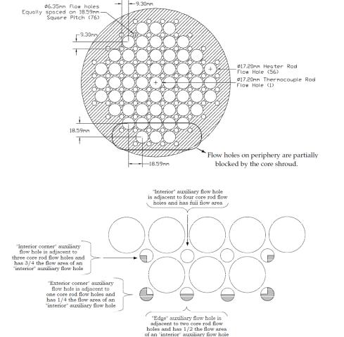
The core is modelled with 56 cylindrical heater rods distributed in a 1.86 cm pitch square array with a 1.33 pitch to diameter ratio. The nominal power of each heater rod is 7.1 kW resulting in a maximum core power of 398 kW. The diameter of the core rod is 1.59 cm.
A lower core flow plate, figure 3, contains 76 auxiliary flow holes of 0.635 cm of diameter, arranged at 1.86 cm pitch square array, and 57 core rod flow holes. In order to create a flow annulus between the flow plate and the core rod, the holes of the rodded lower core flow plate are oversized at 1.72 cm.
The core is shrouded, figure 4, to ensure all flow enters the core via the bottom and travels the entire heated length. The shroud is shaped to partially block the primary coolant flow through the outermost auxiliary flow holes in order to ensure that each heated rod receives approximately equal axial coolant flow. The amount of blockage is dependent on the number and location of heated rods adjacent to each auxiliary flow hole. At mid elevation a core grid wires is considered in order to maintain the radial alignment of the core rods. Four thermocouples for measuring the core inlet temperatures are located at the bottom CL entering the core. The core heater rod temperatures are measured. Six thermocouples vertically spaced every 15.24 cm measuring water temperatures, are located in the center of core thermocouple rod. The pressure loss in the core is measured; the power to the core heater rod bundles is measured.
210 |
Nuclear Power Plants |
The HL riser, figure 2, consists of a lower region, an upper region and a transition region. The lower region consists of a pipe with an outside diameter of 20.32 cm, an inside diameter of 19.71 cm and a wall thickness of 0.305 cm. The upper region consists of a pipe with an outside diameter of 11.43 cm, an inside diameter of 10.23 cm, and a wall thickness of 0.602 cm. The transition region consists of a cone with a 0.305 cm thickness and an half angle of 20.61°. The pressure loss between core top and riser cone, the pressure loss in the riser cone and the pressure loss in the chimney, from the exit of the transition cone to the UP, are measured. Along the riser a thermocouple measures the water temperature inside chimney below SG coil and another one measures the water temperature at top of chimney. The flow rate within the HL chimney is measured with a differential pressure cell used to measure flow. The primary containment water level is measured as well.
Fig. 3. Lower core flow plate layout and auxiliary flow hole blockage by core shroud (Galvin, 2007; Mascari et al., 2011e).

Analysis of Primary/Containment Coupling Phenomena |
211 |
Characterizing the MASLWR Design During a SBLOCA Scenario |
The UP is separated from the heated upper PRZ section by a thick baffle plate having eight 2.54 cm holes, spaced uniformly around the baffle plate periphery, which allow free communication of the PRZ to the remainder of the RPV during normal operation and for volume surges into and/or out of the PRZ due to transients.
Fig. 4. Core shroud photo (Galvin, 2007; Mascari et al., 2011e).
The PRZ is integrated in the RPV and is located in its upper part. In the PRZ are located three heater elements, each 4 kW, that are modulated by the test facility control system to maintain nominal primary system pressure at the desired value. The PRZ steam temperature and pressure are measured. The PRZ level is measured as well.
The CL downcomer region, figure 2, is an annular region bounded by the RPV wall on the outside and the HL riser on the inside, and the flow area reduces at the HL riser cone. In the SG primary side section is inserted the SG helical coil bundle. Thermocouples are located in the CL downcomer region to measure water down flow temperatures after SG coils. The primary side pressure loss across SG and the pressure loss in the annulus below SG are measured.
The SG of the facility is a once through heat exchanger and is located within the RPV in the annular space between the HL riser and the inside surface of the RPV. The tube bundle, is a helical coil consisting of fourteen tubes with a total heated length of 86 m. There are three separate parallel coils of stainless steel tubes. The outer and middle coils consist of five tubes each while the inner coil consists of four tubes. The value of the degree of the steam superheat is changed in order to control the facility. A thermocouple is located at the exit of each helical coil. The main steam pressure and temperature are measured. The main steam mass flow rate is measured with a vortex flow meter. The FW supply in the SG outer, middle and inner coil mass flow rate are measured with flow Coriolis meters. The related pressures are measured. The FW temperature is measured as well.
3.2 OSU-MASLWR containment structures description
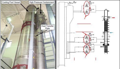
The HPC, figure 5, consists of a lower cylindrical section, an eccentric cone section, an upper cylindrical section and an hemispherical upper end head. For scaling reasons, in order to
212 |
Nuclear Power Plants |
have an adiabatic boundary condition in all the wall of the HPC except through the heat transfer plate wall where the condensation has to take place, four groups of containment heaters have been installed permitting the heat transfer takes place only between the CPV and HPC containment. These heaters are located in the exterior surface of the HPC, under the insulation, and above the containment water level. The temperatures of heaters located on the walls of the HPC and the temperatures within the walls of the HPC, between the heaters and the water, are measured. The entire HPC is covered by Thermo-12 hydrous calcium silicate insulation. The HPC level and pressure are measured.
Fig. 5. OSU-MASLWR containment structures (Reyes et al., 2007; Mascari et al., 2011d; Mascari et al., 2011e).
The CPV consists of a tall right cylindrical tank covered by Thermo-12 hydrous calcium silicate insulation. The CPV level and water temperature are measured. One disk rupture is connected between the HPC and the CPV.
The heat transfer plate, having the same height of the HPC without the hemispherical head, provides the heat conduction between the HPC and CPV. The heat transfer plate is scaled in order to model the heat transfer area between the MASLWR design high pressure containment vessel and the cooling pool in which it sits.
Five thermocouples are located at six different elevations to measure the temperature distribution from the HPC to the CPV. In particular one group of thermocouples measures the water temperatures located inside the HPC near the heat transfer plate, one measures the water temperatures located inside the CPV near the heat transfer plate, one measures the wall temperatures at the midpoint of the heat transfer plate between the CPV and the HPC, one measures wall temperatures within the heat transfer plate between the CPV and the HPC nearest to the HPC and one measures wall temperatures within the heat transfer plate between the CPV and the HPC nearest to the CPV.
Analysis of Primary/Containment Coupling Phenomena |
213 |
Characterizing the MASLWR Design During a SBLOCA Scenario |
3.3 OSU-MASLWR ADS lines description
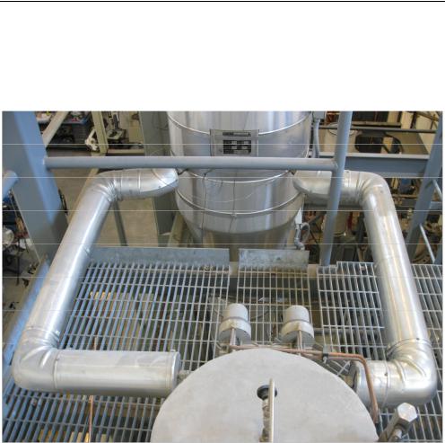
The high ADS lines, figure 6, are horizontally oriented and connect the PRZ steam space with the HPC. A pneumatic motor operated globe valve is located in each line. Downstream from each isolation valve is a transition piece with an internal square-edge orifice. The two high ADS lines enter the HPC above the waterline, penetrate it and then terminate with a sparger.
Fig. 6. High ADS lines photo.
The middle ADS lines are horizontally oriented and connect the RPV CL to the HPC. A pneumatic motor operated globe valve is located in each line. Downstream from each isolation valve is a transition piece with an internal square-edge orifice. These two lines enter the HPC, penetrate it and then turn downward before terminating below the HPC waterline. A sparger is considered at the end of these lines.
The ADS sump recirculation lines are horizontally oriented and connect the RPV lower CL to the HPC. A pneumatic motor operated globe valve is located in each line. Downstream from each isolation valve is a transition piece with an internal square-edge orifice. These two lines enter the HPC, penetrate it and then turn downward before terminating below the HPC waterline. No sparger is considered for these lines.
The water temperatures inside the ADS lines outside of the HPC are measured.
214 |
Nuclear Power Plants |
4. OSU-MASLWR-001 test description
The purpose of the OSU-MASLWR-001 test (Modro et al. 2003; Reyes et al., 2007; Pottorf et al., 2009; Mascari et al., 2011e), a design basis accident for MASLWR concept design, was to determine the pressure behavior of the RPV and containment following an inadvertent actuation of one middle ADS valve. The test successfully demonstrated the blowdown behavior of the MASLWR test facility during one of its design basis accident.
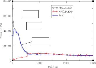
Following the inadvertent middle ADS actuation the blowdown of the primary system takes place. A subcooled blowdown, characterized by a fast RPV depressurization, takes place after the Start Of the Transient (SOT). A two-phase blowdown occurs when the differential pressure, at the break location, results in fluid flashing. A choked two-phase flow condition prevails and a decrease in depressurization rate of the primary system is experimentally observed. When the PRZ pressure reaches saturation, single phase blowdown occurs and the depressurization rate increases. The RPV and HPC pressure and the primary saturation temperature are shown in figure 7. The Psat, saturation pressure, is based on the temperature at the core outlet.
Subcooled
 Blowdown
Two-phase
 Blowdown
Single phase
Blowdown
Fig. 7. RPV and HPC pressure behaviour during the OSU-MASLWR-001 test (Modro et al., 2003; Reyes et al., 2007; Mascari et al., 2011e).
At 539 s after the SOT the pressure difference between the RPV and the HPC reaches a value less than 0.517 MPa, one of the high ADS valve is opened and, with approximately 10 s of delay, the other high ADS valve is opened equalizing the pressure of the primary and HPC system.
At 561 s after the SOT the pressure difference between the RPV and the HPC reaches a value less than 0.034 MPa, one of the sump recirculation valve is opened and, with approximately 10 s of delay, the other sump recirculation valve is opened terminating the blowdown period and starting the refill period. The refill period takes place for the higher relative coolant height in the HPC compared to the RPV. Figure 8 shows the RPV level evolution experimentally detected during the test. The RPV water level never fell below the top of the core during the execution of the test 1.