

NUCLEAR POWER PLANTS
.pdfDeterministic Analysis of Beyond Design Basis Accidents in RBMK Reactors |
55 |
considerable temperature increase is possible only in case of operator non-intervention. Operator has a possibility to reduce coolant discharge through the break by closing the maintenance valves. These actions lead to the water level increase in the affected DS and improve cooling conditions of the fuel channels. The fuel channels of the intact RCS loop is reliably cooled with water supplied by the MCPs and ECCS long-term cooling subsystem.
Temperature,0С
1000
800
600
400
200
-20
3.75 MW |
|
|
|
3.41 MW |
|
|
|
3.35 MW |
|
|
|
2.93 MW |
|
|
|
2.15 MW |
|
Acceptance criterion 700 оС |
|
1.83 MW |
|
|
|
0 |
20 |
40 |
60 |
Time, s
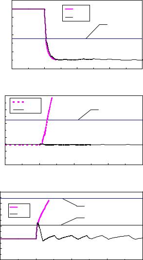
Fig. 13. Break of MCP pressure header with short-term ECCS failure. Temperature of fuel cladding in FC of the affected RCS
|
450 |
|
|
|
|
|
413 |
|
|
|
|
|
|
|
|
|
|
|
|
|
|
Damages are possible |
|
||||
|
400 |
|
|
|
|
|
|
|
|
||||
|
|
|
|
|
|
|
|
(conservative estimation) |
|
||||
|
|
|
|
|
|
|
|
|
|
||||
channels |
350 |
|
|
|
|
|
|
|
|
|
|
|
|
300 |
|
|
|
|
|
|
|
290 |
|
|
|
|
|
|
|
|
|
|
|
253 |
|
|
|
Damages are |
|||
|
|
|
|
|
|
|
|
|
|
||||
250 |
|
|
|
|
|
|
|
|
|
possible (detailed |
|||
|
|
|
|
|
|
|
|
|
|
||||
of |
200 |
|
|
|
|
187 |
|
|
|
|
|
analysis) |
|
Number |
|
|
|
|
|
|
|
|
|
|
|
||
|
|
|
159 |
|
|
|
|
|
|
|
|
||
|
|
|
|
|
|
|
|
138 |
|
|
|
||
150 |
|
|
|
|
|
|
|
|
|
|
|
||
|
|
|
|
|
|
|
|
|
|
|
|
||
|
|
|
84 |
|
|
|
|
|
|
|
|
|
|
|
100 |
|
53 |
|
|
|
|
|
|
|
|
|
|
|
50 |
|
|
|
|
|
|
|
|
46 |
|
|
|
|
18 |
|
|
|
|
|
|
|
|
|
|
||
|
|
|
|
|
|
|
|
|
|
14 |
1 |
||
|
|
|
|
|
|
|
|
|
|
|
|||
|
0 |
|
|
|
|
|
|
|
|
|
|
|
|
|
|
|
|
|
|
|
|
|
|
|
|
|
|
|
|
1116 |
1364 |
1654 |
1974 |
2222 |
2480 |
2739 |
2976 |
3255 |
3410 |
3514 |
3750 |
Channels power, kW
Fig. 14. Break of MCP pressure header with short-term ECCS failure. Estimation of the number of failed fuel channels (conservative estimation versus detailed analysis using RELAP/SCDAPSIM code)
For the case of medium LOCA in Zone 1 a detailed analysis is not carried out as the consequences this event is covered by medium LOCA in Zone 2. Short-term increase of temperatures of fuel rod cladding and FC walls is not observed at the initial stage of the accident at the GDH break upstream the check valve (medium LOCA in RCS Zone 1), but is traced at the break downstream the check valve (LOCA in Zone 2).
56 |
Nuclear Power Plants |
|
8 |
MPa |
6 |
|
|
Pressure, |
4 |
|
|
|
2 |
Pressure inside fuel element
Pressure outside fuel element
0
-5 |
0 |
5 |
10 |
15 |
20 |
Time, s
Fig. 15. Break of MCP pressure header with short-term ECCS failure. Pressure inside and outside the fuel rod (element) in the fuel channel with initial 3.4 MW power
5.2.2 LOCA in Zone 2
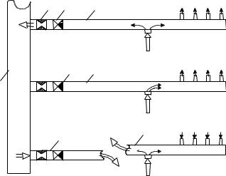
The consequences of LOCA in Zone 2 are similar to the consequences of LOCA in Zone 1. In both cases the break location is upstream the reactor core. Moreover, the phenomena in both cases are similar. In case of GDH break the coolant supply is terminated through 39 – 43 fuel channels connected to the distribution header of this group. In case of GDH guillotine break downstream check valve, the coolant in FCs connected to the affected GDH starts to flow in the opposite direction from DSs (Figure 16). Loss of the coolant from DS is compensated by
3
1 |
2
Fig. 16. GDH break downstream check valve. Structure of coolant flows: 1 – GDH break; 2 – ECCS water supply into the core; 3 – coolant supply through pressure header - ECCS bypass
Deterministic Analysis of Beyond Design Basis Accidents in RBMK Reactors |
57 |
ECCS water. Short-term fuel cladding and fuel channel wall temperatures increase is observed at the beginning of the accident due to the coolant flow direction change as in the case of LOCA in Zone 1. During partial breaks of GDH pipe, or in case of guillotine break of one GDH with the failure of check valve in the adjacent GDH (Figure 17), the coolant flow rate stagnation is possible in FCs connected to the affected GDH in this zone. In case of lower water piping break, coolant supply is terminated only into one FC.
7 |
6 |
5 |
DECREASED FLOW RATE FROM ECCS TO FC |
|
|
|
|||
GDH TO PH |
|
|
|
|
FLOW FROM |
|
|
|
ECCS WATER SUPPLY |
4 |
3 |
|
FLOW RATE FROM ECCS TO FC |
|
|
|
|
||
1 |
|
|
|
|
|
|
|
|
ECCS WATER SUPPLY |
|
|
DISCHARGE FROM BREAK |
REVERSE COOLANT FLOW RATE FRO |
|
|
|
FROM CORE |
|
|
|
2 |
|
|
2 |
|
|
|
|
|
|
|
DISCHARGE FROM BREAK |
ECCS WATER SUPPLY |
|
|
|
FROM PH |
|
|
|
|
|
|
|
Fig. 17. Guillotine break of GDH downstream check valve at failure of check valve in adjacent GDH: 1 – MCP pressure header, 2- broken GDH, 3- normal GDH, 4 – check valve, 5
– GDH with fail to close check valve, 6 – fail to close check valve, 7 – flow limiting device
There are no pipelines with a diameter bigger than 300 mm, thus the large LOCAs in Zone 2 were not analyzed. For the medium LOCA in Zone 2, the following was considered: GDH guillotine break, GDH partial break resulting into stagnation of coolant flow rate and GDH guillotine break at failure to close the check valve in the adjacent GDH:
The analysis of GDH guillotine break at complete ECCS failure and at operation of one, two or three ECCS pumps demonstrated that for reliable cooling of the core at a long stage two ECCS pumps are enough. With such number of ECCS equipment, after one hour from the beginning of the accident, the ECCS water flow rate starts to exceed water discharge through the break. However, short-term increase in temperatures of fuel rod cladding and FC walls at the initial stage of accident in FCs, connected to the broken GDH, is inevitable in any case. The excess of acceptance criterion for fuel rod cladding (700 oС) is probable in 12 FCs. A more detailed analysis (using RELAP/SCDAPSIM model presented in Fig. 7) shows that this short temperature peak does not lead to the failure of any fuel rods.
In the case of coolant flow rate stagnation in channels, multiple FCs breaks are probable after approximately 20 s from the beginning of the accident if the reactor is not shutdown on time. On the contrary, if a reactor is shutdown quickly (until the FCs heat
up), the acceptance criterion for channels walls will not be violated and the channels
58 |
Nuclear Power Plants |
will remain intact. The conditions for the reactor long-term cooling remain similar to GDH break: the operation of two ECCS pumps is necessary.
In the case of GDH break with a failure to close the check valve in the adjacent GDH, ECCS water supply worsens the cooling conditions of the channels connected to the GDH with failed to close check valve. It occurs that ECCS water interferes with the reverse coolant flow rate through these FCs. Stagnation of coolant flow rate is formed in these FCs. However, ECCS water supply helps to fill DSs and to ensure cooling of channels in the intact RCS loop and the channels connected to the 18 GDHs of the affected RCS loop. The analysis of GDH break with failure to close the check valve in the adjacent GDH is carried out at the operation of 1 - 4 ECCS pumps. The results of the analysis showed that for the reliable cooling of FC, connected to other 18 GDHs of the affected RCS loop, it is necessary to have not less than two operating ECCS pumps in long-term cooling subsystem. The channels connected to the GDH with failed to close check valve will be cooled because of radial heat transfer between the adjacent graphite blocks.
For the small LOCA in Zone 2, guillotine and partial breaks of lower water pipe were considered:
The results of the analysis of guillotine break of the lower water pipe showed that the reactor core is reliably cooled during the first minutes after the accident in this case. One ECCS pump is enough for the reactor long-term cooling. The pump should be started during the first hour after the beginning of the accident.
The performed analysis demonstrated that in the worst case, at partial break of the lower water pipe, the signal on the reactor shutdown on pressure increase in ALS compartments can not be generated. If the partial break causes stagnation of the coolant flow rate through the affected FC, it will lead to the heat up and break of this channel. The peak temperature of fuel in the affected channel will not reach the temperature of melting, i.e. 2800 оС. After the break of the channel pipe, pressure in the reactor cavity increases, which results in the formation of a signal on the reactor shutdown. After the fuel channel wall break the conditions of flow stagnation will be destroyed and the broken parts of fuel channel and fragments of fuel assemblies below and above the break will be cooled by coolant flow from the top and bottom. The remaining intact fuel channels will also be reliably cooled. It is necessary to note that for RBMK type reactors the rupture of a single FC is a design basis accident. Such accident would correspond to a small breach in the reactor vessel of BWR. Steam-gas mixture from RC will be discharged through the reactor cavity venting system to the left tower of ALS. The steam will be condensed, fission products will be scrubbed in the condensing pool, but will not be discharged to the environment. Thus, the damaged fuel assembly will be contained in the reactor cavity.
5.2.3 LOCA in Zone 3
A single fuel channel break is the accident when the fuel channel is overheated during the reactor operation on power at nominal pressure. In case of other accidents that are included in this group (1.2, see Figure 5), the overheating of fuel can occur after the reactor shutdown at low pressure in RCS, because the strength of fuel channels at nominal pressure at the temperature margin of 650–800 oC is limited [4]. Otherwise (if FC walls temperature exceeds this limit in few fuel channels during normal pressure in the circuit) multiple ruptures of fuel channels can occur. As design basis accident for RC is a single FC rupture, the accident with
Deterministic Analysis of Beyond Design Basis Accidents in RBMK Reactors |
59 |
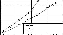
multiple ruptures of fuel channels is included into the group of accidents when the reactor core is completely damaged and the integrity of the reactor constructions is not preserved. The reactor cavity venting system at Ignalina NPP with RBMK-1500 reactor was improved providing the additional flow path to ALS, i.e. the RCVS capacity was increased to withstand a multiple rupture of fuel channels. Figure 18 presents the summary of the analysis performed to estimate the number of fuel channels that can be ruptured simultaneously in the beginning of the accident, i.e. at nominal RCS pressure and temperature, and reactor power of 4200 MWth, the integrity of the reactor cavity would be maintained. A detailed analysis is presented in [21]. The coolant release rate was calculated using code RELAP5 (model presented in Figure 6) and the analysis of the Reactor Cavity and ALS response was performed using code CONTAIN. The performed analysis showed that making the most conservative assumptions, the reactor cavity could withstand simultaneous rupture of at least 11-16 FCs.
|
250 |
|
|
|
|
RC, kPa |
200 |
|
|
|
|
150 |
|
|
|
|
|
in |
|
|
|
|
|
Pressure |
100 |
|
|
|
|
50 |
|
|
With DROPOUT model |
|
|
|
|
Without DROPOUT model |
|
||
|
0 |
|
|
Minimal permissible pressure |
|
|
|
|
|
|
|
|
0 |
5 |
10 |
15 |
20 |
|
|
Number of ruptured FC |
|
||
Fig. 18. Pressure in the reactor cavity as a function of a number of ruptured FCs [21]
5.2.4 LOCA in Zone 4
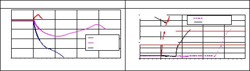
Pressure sharply decreases in DSs and RCS in the case of LOCA in Zone 4, but coolant circulation through the reactor core can be destroyed only in the latest stages of the accident, when pressure in RCS drops below 0.4 MPa. Thus, the characteristic fuel cladding and channel walls temperature peak within the first seconds of the accident (in case of LOCA in Zone 1 and Zone 2) is not met there. Guillotine breaks of one and two steamlines were considered for the large LOCA in RCS Zone 4:
The results of the analysis showed that at LOCA in Zone 4 the operation of ECCS shortterm subsystem is not necessary, i.e. the temperature of fuel rod cladding and FC walls is much lower than acceptance criteria without operation of this subsystem.
For reliable cooling of the reactor core in long-term post-accidental period, it is necessary to have not less than two ECCS pumps in operation in the case of two steamlines break, and not less than one pump in the case of one steamline break.
In case of breaks in Zone 4 without the reactor shutdown (break of steamlines), the temperature rises much more slowly (especially the temperature of FCs walls). This specifies that such breaks in Zone 4 are less dangerous, than breaks in Zone 1 (Fig. 19). In the case without the reactor shutdown, the melting of the core at low pressure in RCS is probable, but does not result in the immediate damage of the reactor cavity.
60 |
Nuclear Power Plants |
|
|
|
Pressure in DS |
|
|
|
Peak temperatures of fuel cladding |
|
|||||
|
8.0 |
|
|
|
|
|
|
|
|
|
|
|
|
|
|
|
|
|
|
|
1800 |
MCP PH break |
|
one steamline break |
|
||
|
7.0 |
|
|
|
|
|
1600 |
|
|
|
|
||
|
|
|
|
|
|
|
|
|
two steamlines break |
|
|||
|
|
|
|
|
|
|
|
|
|
|
|
||
Pressure, MPa |
|
|
|
|
|
С |
1400 |
|
Safety limit 1200 оС |
|
|
|
|
6.0 |
|
|
|
|
о |
1200 |
|
|
|
|
|
||
|
|
|
|
|
Temperature, |
|
|
|
|
|
|
||
5.0 |
|
|
|
MCP PH break |
1000 |
|
|
|
|
|
|
||
|
|
|
|
|
|
|
700 оС |
|
|
|
|||
|
|
|
|
one steamline break |
800 |
Acceptance criterion |
|
|
|
||||
4.0 |
|
|
|
two steamlines break |
600 |
|
|
|
|
|
|
||
|
|
|
|
|
|
|
400 |
|
|
|
|
|
|
|
3.0 |
|
|
|
|
|
200 |
|
|
|
|
|
|
|
-50 |
0 |
50 |
100 |
150 |
200 |
|
-50 |
0 |
50 |
100 |
150 |
200 |
|
|
|
|
Time, s |
|
|
|
|
|
|
Time, s |
|
|
Fig. 19. Comparison of accident consequences in case of breaks in Zone 1 (MCP PH break) and Zone 4 (steamlines break)
5.3 Analysis of accidents when heat-up of the reactor core occurs during the reactor operation or within the first seconds after the reactor shutdown
The second category of core damage (see Figure 5), accidents with loss of the general structure integrity of the reactor and ALS, can potentially be due to the possibility of multiple ruptures of fuel channels at high pressure in RCS. The structural integrity of RBMK-1500 reactor depends on the integrity of the reactor cavity, which with a conservative strength margin was designed for conditions of an anticipated accident caused by the rupture of a single channel (in the nominal operating regime of a reactor). During operation of all nuclear power plants with RBMK reactors, there were three cases of fuel channel rupture, but the neighboring channels were not damaged [4]. This shows that the neighboring fuel channel– graphite cells have sufficient strength and elasticity and that the load caused by the rupture of a single channel is small. The accidents, leading to the complete reactor core damage, with loss of the structural integrity of the reactor can be divided into two groups [9]:
accidents when heat-up of the reactor core occurs during the reactor operation or within the first seconds after the reactor shutdown, when decay heat is high (2.1, see Fig. 5);
accidents when heat-up of the reactor core occurs after the reactor shutdown (2.2, see Fig. 5).
The first group of accidents (2.1) includes accidents when the heat-up of the reactor core occurs in the beginning of the accident (a few seconds after reactor scram activation) when decay heat in the core is high and the temperatures of fuel cladding and FC walls in the group of channels can reach the dangerous limits. An example of such accidents is the group of accidents, when the local flow stagnation occurs in the group of fuel channel during the LOCA. This situation is possible in the partial break case [12, 22]. It was mentioned earlier that partial rupture of lower water pipe could lead to the flow stagnation in the affected fuel channel. In the case of GDH partial rupture, the flow stagnation can occur in all fuel channels connected to this affected GDH. Under adverse conditions, the partial break of MCP pressure header can cause flow stagnation in the fuel channels of one affected loop. Since there is no sufficient time for actions of the operator in this case, the short-term accident management measures (automatic actuation of safety systems) are necessary. New reactor protection against coolant flow rate decrease through GDH generated signal for early ECCS activation is implemented in RBMK-1500 in this case. This short-term measure leads to the disturbance of the coolant flow rate stagnation in the group of fuel channels [12] and all parameters of RCS, thus, the reactor remains within safe limits.
Deterministic Analysis of Beyond Design Basis Accidents in RBMK Reactors |
61 |
Other examples of the first group of accidents (2.1) can also be the initiating events, namely:
Anticipated Transients Without reactor Scram (ATWS);
GDH blockage;
Loss of natural circulation due to a sharp decrease of pressure in the RCS.
The analysis of ATWS (performed for the RBMK-1500 in 1996) demonstrated [3] the lack of inherent safety features in the RBMK design. The power is not reduced by means of inherent physical processes such as steam generation. The reactivity loss due to the fuel temperature rise (Doppler Effect) is not sufficient. The consequences of the accident for RBMK-1500 reactor, during which the loss of preferred electrical power supply and failure of automatic reactor shutdown occurred, are presented in Figure 20. The analysis was performed using RELAP5 model, presented in Figure 6.
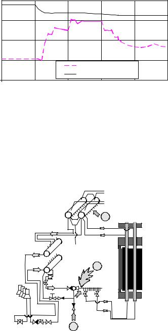
Due to the loss of preferred electrical power supply all pumps are switched off (see Figure 20 (a)); therefore, the coolant circulation through the fuel channels is terminated. Because of the lost circulation, fuel channels are not cooled sufficiently and for this reason, the temperature of the fuel channel walls starts to increase sharply. As it is seen from Figure 20 (b), already after 40 seconds from the beginning of the accident, the peak fuel channel wall temperature in the high power channels reaches the acceptance criterion of 650 oC. It means that because of the further increase of the temperature in the fuel channels, plastic deformations begin, i.e. because of the influence of internal pressure, the channels can be ballooned and ruptured. During the first seconds of the accident, the main electrical generators and turbines are switched off as well. Steam generated in the core is discharged through the steam discharge valves, but their capacity is not sufficient Therefore, the pressure in the reactor cooling system increases and reaches acceptance criterion 10.4 MPa approximately after 80 seconds from the beginning of the accident (see Figure 20 (c)). Further increase of the pressure can lead to a rupture of pipelines.
Thus, the analysis of the anticipated transients without the shutdown demonstrated that in some cases the consequences can be quite dramatic for the RBMK-1500 reactors. Hence, in 1996 the priority recommendation was formulated as follows: to implement a second diverse shutdown system based on other principles of operation,. The implementation of such system requires much time and financial sources, thus at first it was decided to implement a compensating measure: a temporary shutdown system. This temporary system was called by the Russian abbreviation „DAZ“ („Dopolnitelnaja avarijnaja začita“ – „Additional emergency protection“). This system used the same control rods as well as design reactor shutdown system, however, signals for this system control were generated independently in respect of the design reactor shutdown system. The analysis performed to justify the selected set points for reactor scram activation showed that after the implementation of DAZ system, the reactor is shutdown on time and cooled reliably; moreover, the acceptance criteria are not violated even in case of transients when the design reactor shutdown system does not function. Figure 20 presents the behavior of the main parameters of the reactor cooling system in case of the loss of the preferred electrical power supply and simultaneous failure of the design reactor shutdown system [23]. In this case two signals for activation of DAZ system (reactor shutdown) are generated: on the increase of pressure in the drum-separators and on the decrease in the coolant flow rate through the main circulation pumps. In Unit 1 DAZ system was installed in 1999, in Unit 2 in 2000. Later (in 2004) the second diverse shutdown system
62 |
Nuclear Power Plants |
was installed in the Ignalina NPP Unit 2. After these modifications the frequency of ATWS at Ignalina NPP became negligible (<10-7/year).
single |
|
8000 |
|
|
|
a |
|
|
|
ATWS |
|
||
|
|
|
|
|
|
|
through |
/h |
6000 |
|
DAZ |
2 |
|
|
|
|
|
|
||
3 |
|
|
|
|
|
|
m |
|
|
|
|
|
|
flow rate |
MCP, |
4000 |
|
|
|
|
2000 |
|
|
|
|
||
Coolant |
|
|
|
|
|
|
|
0 |
|
|
|
|
|
|
|
|
|
|
|
|
|
|
-200 |
0 |
200 |
400 |
600 |
|
|
|
|
Time, s |
|
|
|
1000 |
ATWS |
|
|
b |
|
|
|
1 |
||
|
800 |
DAZ |
|
|
|
C |
|
|
|
||
|
|
|
|
|
|
o |
|
|
|
|
|
Temperature, |
600 |
|
|
|
|
400 |
|
|
|
|
|
|
|
|
|
|
|
|
200 |
|
|
|
|
|
0 |
|
|
|
|
|
-200 |
0 |
200 |
400 |
600 |
Time, s
|
11 |
|
|
|
|
|
10 |
ATWS |
|
1 |
c |
MPa |
|
|
2 |
||
9 |
DAZ |
|
|
||
|
|
|
|
||
|
|
|
|
|
|
Pressure, |
8 |
|
|
|
|
7 |
|
|
|
|
|
|
6 |
|
|
|
|
|
5 |
|
|
|
|
|
-200 |
0 |
200 |
400 |
600 |
Time, s
Fig. 20. Analysis of loss of preferred electrical power supply and simultaneous failure of design reactor shutdown system, when DAZ system was installed: a) coolant flow rate through one main circulation pump, b) the peak fuel channel wall temperature in the high power channel, c) pressure behaviour in drum - separators, 1 – acceptance criterion, 2 – set points of DAZ system activation (reactor shutdown)
Deterministic Analysis of Beyond Design Basis Accidents in RBMK Reactors |
63 |
The GDH blockage for RBMK-1500 also depends on such group of accidents when during normal operation a group of fuel channels is overheated and multiple rupture of FC can occur. It is shown [12] that the coolant flow through the ECCS bypass line is not enough to cool down the fuel channels connected to the blocked GDH. The critical heat flux would appear in some fuel channels and cause failure of fuel claddings and FC walls. In the year 2000 a new reactor scram (emergency shutdown) signal based on coolant flow rate decrease through GDH was implemented at Ignalina NPP. The new signal ensures the timely reactor shutdown so that the dangerous fuel cladding and FC walls temperatures are not reached [12]. Therefore, this accident is moved from the group of severe accidents into the group of accidents without core damage.
The accidents when the loss of natural circulation occurs due to a sharp decrease of pressure in the RCS (due to break of steamlines) are presented in section 5.2.4. Some parts of steamlines are located in the compartments without pressure gauges. Thus, there is no direct signal indicating that the steamline break occured in these compartments (as in the other cases the pressure increase in compartments indicates coolant discharge through the break). It means that signals for the reactor shutdown and ECCS activation will be generated with delay on the basis of secondary parameters (e.g., water level decrease in DSs). On the other hand, a sharp pressure drop in the RCS is a characteristic feature in the case of RBMK steamline break; it destroys the natural circulation of coolant through the core. The flow stagnation in the core together with the late reactor shutdown can cause overheating of group of fuel channels. This was mentioned in the safety analysis report of Ignalina NPP [3] and the review of safety analysis report [24]. In the year 1998 - 1999 a new reactor scram signal based on fast pressure decrease in DS was implemented at Ignalina NPP. This modification allowed avoiding the overheating of a group of fuel channels.
5.4 Analysis of accidents when heat-up of the reactor core occurs after the reactor shutdown
The second group of accidents from the second category of BDBA (total damage of the core or its components with the reactor maintaining its overall structural integrity) are the accidents when heat-up of the reactor core occurs after the reactor shutdown (2.2 – see Figure 5). The heat-up, damage and melting of the reactor core could occur in the late phase after the reactor shutdown due to loss of the long-term cooling. The results of the Level 1 probabilistic safety assessment of the Ignalina NPP showed that in the topography of the risk, transients dominate above the accidents with LOCAs and the failure of the core long-term cooling are the main factors of the frequency of core damage. The initiating events leading to the loss of long term cooling accident are such:
loss of intermediate cooling circuit;
loss of service water;
station blackout.
The station blackout (the most likely initiating event) is the loss of normal electrical power supply for local needs with an additional failure on start-up of all diesel generators. In the case of loss of electrical power supply MCPs, the circulating pumps of the service water system and feedwater supply pumps are switched-off. The failure of diesel generators leads to the non-operability of the emergency long-term core cooling subsystem. It means the
64 |
Nuclear Power Plants |
impossibility to feed RCS by water. The results of the analysis [20, 25] suggest that approximately 1.5 hours after the beginning of the accident, a dangerous heat-up of fuel rods and FC walls starts. Three ways of potential accident management for the loss of the long-term core cooling were discussed in [25]:
decay heat removal by ventilation of DS compartments,
decay heat removal by direct water supply into the reactor cavity,
de-pressurisation of the reactor coolant system and water supply to the GDH from ECCS hydro-accumulators, deaerators or using non-regular means.
The results showed that the first two ways are inexpedient. The ventilation of DS compartments and the direct water supply into the RC are not sufficient to remove the decay heat from the core. However, the de-pressurisation of RCS and the following water supply from regular and non-regular means to the GDH in the case of loss of long-term cooling gives considerably better results compared with the other two measures. The performed analysis [25] demonstrated that the reactor core cooling by RCS depressurisation and water supply from deaerators give additional four hours for the operator to install water supply from the external (artesian) water source. Thus, this way of accident management is recommended to be included in the RBMK-1500 accident management programme.
In the case of loss of intermediate cooling circuit or loss of service water, the consequences of the accidents will be very similar. In these last cases there are no direct signals for the reactor shutdown; however, these initiating events lead to the loss of feedwater supply and MCP will be tripped due to the insufficient cooling. Reactor scram would appear on secondary parameters and further sequence of the accident will be the same as in case of the station blackout: due to decay heat the water in the core is evaporating and the core heat-up process starts. Core overheating can be avoided by using water stored in the ECCS hydroaccumulators, deaerators and other water sources located at NPP.
Figure 21 shows the behavior of fuel, claddings, channel walls, and graphite stack temperatures, calculated using RELAP5 and RELAP5/SCDAPSIM codes (models presented in Figure 6 and Figure 7), in case of RBMK-1500 reactor blackout, without any additional water supply. Such event, which is developing into a severe accident, serves as an example for the discussion of severe accident phenomena in RBMK type reactors. As it is presented in Figure 21, the failure of fuel channels could occur after ~3 hours. The failure of FCs is expected because the pressure in RCS is nominal, and the acceptance criterion for fuel channel (650 °C) will be reached (Figure 21). It is assumed that after ~3.8 hours the operator opens one steam relief valve to discharge steam from RCS. This action allows depressurizing RCS and prevents ruptures of FCs. If no operator actions were taken (no manual depressurization), then approximately 50 FCs with a higher power level could be ruptured. If all FCs ruptured within short time interval, the reactor cavity would be destroyed and the consequences of the accident would be similar to the Chernobyl accident.
Figure 22 shows the long-term behavior of fuel, claddings, fuel channels, and graphite stack temperatures, calculated using RELAP5/SCDAPSIM code (model presented in Figure 7), in case of RBMK-1500 reactor blackout, with operator intervention (opening one of steam relief valves for RCS depressurization). As the operator starts depressurization, the accident scenario continues at low pressure. Due to the pressure decrease the rest of coolant in pipelines below the reactor core starts boiling and steam cools down the core for a short