

NUCLEAR POWER PLANTS
.pdfEvolved Fuzzy Control System for a Steam Generator
The Ny – step prediction of the output by the jth |
FI can be rewritten as follows: |
|||||||||||
ˆ j |
n A |
j |
j |
n Y n P |
j |
|
j |
|
||||
Y |
|
U |
|
n E n |
||||||||
where: |
|
|
|
|
|
|
|
|
|
|
|
|
|
|
aj |
|
0 |
|
0 |
|
|
|
0 |
|
|
|
|
1 |
|
aj |
|
0 |
|
|
|
0 |
|
|
|
|
aj |
|
|
|
|
|
|
|
|||
|
|
2 |
|
1 |
|
a1j |
|
|
|
|
|
|
A j |
a3j |
|
a2j |
|
|
|
|
0 |
||||
|
|
|
|
|
|
|
|
|
|
|
|
|
|
|
|
|
|
|
|
|
|
|
|
||
|
aj |
|
aj |
|
aj |
|
|
|
aj |
|
|
|
|
|
Ny |
|
Ny 1 |
Ny 2 |
|
|
Ny Nu 1 |
|
|||
|
|
|
|
|
|
|||||||
|
|
|
|
|
|
|
|
|
|
|
||
i
aij hkj
k 1
Y n yDal n yDal n y n Dal T
P j n P1j n P2j n PNj y n T
|
|
2 |
|
T |
|
Ny |
|
||
Ej n |
0 |
j n k 1 j n k 1 |
||
|
|
k 1 |
k 1 |
|
|
|
|
||
i T
Pij n hlj u n k l
k 1 l k 1
The resulting control policy for the jth subsystem can be derived as
J j n U j n T A jT W1jA W2j U j n
U j n T A jT W1jZj n
Zj n T W1jA j U j n Zj n T W1jZj n
where:
Zj n Y n Yr n P j n Ej n
Minimizing (26) yields
J j n |
|
jT |
j j |
j |
j |
|
2 A |
|
W1A |
W2 |
U n |
j |
|
||||
U n |
|
|
|
|
|
2A jT W1jZj n 0
25
(21)
(22)
(23)
(24)
(25)
(26)
(27)
(28)
(29)
(30)
26 |
Nuclear Power Plants |
The control law by the jth FI can be identified as |
|
U j n K jZj n |
(31) |
K j A jT W1jA j W2j 1 A jT W1j |
(32) |
The optimal global control policies can be derived at the upper layer. |
|
U n u n u n 1 u n Nu 1 T |
(33) |
3.3 Parameter tuning
In controller design, the difficulty encountered is how to quickly minimize the upper bound of the objective function so that the control actions can force a process to track a specified trajectory as close as possible.
There has no rigorous solution to the selection of optimal control horizon (Nu) and prediction horizon (Ny).
The model horizon is selected so that T t open loop settling time.
The ranges of weighting factors W1j and W2j can be very wide, the importance is their relative magnitudes. The following procedure to tune the weighting factors is proposed:
-Select a value for W1 and assign it to all local controllers. Determine W2j independently for each local controller in order to minimize the objective function for that subsystem
-Identify the largest W2 and assign it to all subsystems.
Examine the system’s closed-loop dynamic performance. Reduce the value of W2 gradually until the desirable dynamic performance is identified.
3.4 Simulations
Process Modeling: The main problem in setting up a signal flow diagram for a level controlled system in a SG can be found in the inhomogeneous contents of the SG.
The filling consists of water at boiling temperature, pervaded by steam bubbles.
Since the volume fraction of the steam bubbles is quite considerable, the mean specific weight of the contents is very strongly dependent on the proportion of steam.
This, of course, means that the steam content also strongly influences the level in the SG. The steam content itself depends, in turn, on the load factor, on the changes in feed-water flow, and on feed-water temperature.
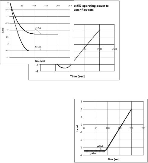
The presence of steam below the liquid level in the SG causes the shrink-and-swell phenomenon that in spite of an increased supply of water, the water level initially falls. Figure 2 shows responses of the water level to steps in feed-water and steam flow-rates at different operating power levels (Irving et al., 1980).

Evolved Fuzzy Control System for a Steam Generator |
27 |
Particularly it is difficult to control automatically a steam generator water level during transient period or at low power less than 15% of full power because of its dynamic characteristics.
The inverse response behavior of the water level is most severe at low power (5%).
The changing process dynamics and the inverse response behavior significantly complicate the design of an effective water level control system.
A solution to this problem is to design local linear controllers at different points in the operating regime and then applies gain-scheduling techniques to schedule these controllers to obtain a globally applicable controller.
Consider a step in feed-water flow rate at 5% operating power. For this system, a fuzzy convolution model consisting of four fuzzy implications is developed as follows:
For j=1 to 4:
R j : if yD |
n is Aj |
|
|
|
||
al |
|
|
|
(34) |
||
|
yDj |
n 1 yDj |
200 |
|||
then |
n h _ Dal ju n 1 i |
|
|
|||
|
al |
|
al |
i 1 |
|
|
|
|
|
|
|
|
|
|
|
|
|
|
||
Responses of water level to a |
Responses of water level to a |
|
|
|||
|
|
|
step in steam flow-rate |
|
|
|
|
step in feed-water flow -rate |
|
|||||
|
|
|
|
|
|
|
|
|
|
|
|
|
|
|
|
|
|
|
|
|
|
|
|
|
|
|
|||
|
|
|
|
|
|
|
|
|
|
|
|
|||
|
|
|
|
|
|
|
|
|
|
|
|
|||
|
|
|
|
|
|
|
|
|
|
|
|
|
||
|
|
|
|
|
|
|
|
|
|
|
|
|
|
|
|
|
|
|
|
|
|
|
|
|
|
|
|
|
|
|
|
|
|
|
|
|
|
|
|
|
|
|
|
|
|
|
|
|
|
|
|
|
Level |
|
|
|
|
|
|
Level |
|
|
|
|
|
|
|
|
|
|
|
|
||
|
|
|
|
|
|
|
|
|||||||
|
|
|
|
|
|
|
|
|
|
|
||||
|
|
|
|
|
|
|
|
|
|
|
|
|||
|
|
|
|
|
|
|
|
|
|
|
|
|||
|
|
|
|
|
|
|
|
|
|
|
|
|
||
|
|
|
|
|
|
|
|
|
|
|
|
|
|
|
|
|
|
|
|
|
|
|
|
||||||
|
|
|
|
|
|
|
|
|
|
|
|
|
|
|
|
|
|
|
|
|
|
|
|
|
|
|
|
|
|
|
|
|
|
|
|
|
|
|
|
|
|
|
||
|
|
|
|
|
|
|
|
|
|
|
|
|
||
|
|
|
|
|
|
|
|
|
|
|
|
|
|
|
|
|
|
Time [sec] |
|
|
|
|
|
|
|
Time [sec] |
|
|
|
|
|
|
|
|
|
|
|
|
|
|
||||
|
|
|
|
|
|
|
|
|
|
|
|
|||
|
|
|
|
(a) |
|
|
|
|
|
|
|
(b) |
|
|
Fig. 2. Responses of water level at different operating power (indicated by %) to (a) a step in feed-water flow –rate. (b) a step in steam flow-rate.
Figure 3. shows the response of water level at 5% operating power to a step in feed-water flow –rate. In Figure 4 the system is decomposed into 4 subsystems: yD1 al , yD2 al , yD3 al , yD4 al .
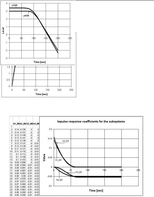
Figure 5 shows the impulse response coefficients for yD1 al , yD2 al , yD3 al , yD4 al subsystems and Figure 6 shows the definition of fuzzy sets A1, A2, A3 and A4. Consider a step in steam flow rate at 5% operating power.
28 |
Nuclear Power Plants |
For this system, a fuzzy convolution model consisting of four fuzzy implications is developed as follows:
For j=1 to 4:
R j : if yD |
n is Aj |
|
|
|
0 |
|
|
(35) |
|
|
yDj 0 |
n 1 yDj |
200 |
|
then |
n h _ D0iju n 1 i |
|
||
|
|
0 |
i 1 |
|
|
|
|
|
|
Fig. 3. Response of water level at 5% operating power to a step in feed-water flow –rate
Fig. 4. The system is decomposed into 4 subsystems: yD1 al , yD2 al , yD3 al , yD4 al

Evolved Fuzzy Control System for a Steam Generator |
29 |
Fig. 5. The impulse response coefficients for yD1 al , yD2 al , yD3 al , yD4 al subsystems
yD |
|
0 |
2 |
|
|
|
|
|
|
|
|
|
yD |
|
0 |
3 |
|
4 |
|
|
|
||||||||||||||
|
|
|
1 |
|
|
|
|
|
|
||||||||||||||||||||||||||
|
al |
|
|
|
|
yDal |
|
yDal |
|
|
|
al |
|
|
|
|
yDal |
yDal |
|||||||||||||||||
|
yD |
al |
|
|
|
|
|
|
yD |
al |
|
|
|
||||||||||||||||||||||
|
|
|
|
|
|
|
|
|
|
|
|
|
|
|
|
|
|
|
|
|
|
|
|
|
|
|
|
|
|
|
|
||||
|
|
|
|
|
|
|
|
|
|
|
|
|
|
|
|
|
|
|
|
|
|
|
|
|
|
|
|
|
|
|
|
|
|
||
|
|
|
1 |
|
|
|
|
|
|
|
|
|
|
|
|
|
|
|
|
|
|
|
1 |
|
|
|
|
|
|
|
|
|
|
|
|
|
|
|
|
|
|
|
|
|
|
|
|
|
|
|
|
|
|
|
|
|
|
|
|
|
|
|
|
|
|
||||||
|
|
|
|
|
|
|
|
|
|
|
|
|
|
|
|
|
|
||||||||||||||||||
|
min(yDal2 ) 0,9 |
|
|
min(y1Dal) 0,2 |
|
min(yDal3 ) 0,9 |
min(yDal4 |
) 0,2 |
|||||||||||||||||||||||||||
|
|
|
|
|
|
|
|
|
|
|
|
|
|
|
|
|
|
|
|
|
|
|
|
|
|
|
|
|
|
|
|
|
|
|
|
Fig. 6. Definition of fuzzy sets A1, A2, A3 and A4 for FI R1, R2 ,R3 and R4 respectively.
Figure 7 shows the response of water level at 5% operating power to a step in steam flow –rate.
Fig. 7. Response of water level at 5% operating power to a step in steam flow –rate;
30 Nuclear Power Plants
In Figure 8 the system is decomposed into 4 subsystems: yD1 0 , yD2 0 , yD3 0 , yD4 0 .
Figure 9 shows the impulse response coefficients for yD1 0 , yD2 0 , yD3 0 , yD4 0 subsystems, Figure 10 shows the definition of fuzzy sets A1, A2, A3 and A4.
Fig. 8. The system is decomposed into 4 subsystems: yD1 0 , yD2 0 , yD3 0 , yD4 0 .
Fig. 9. The impulse response coefficients for yD1 0 , yD2 0 , yD3 0 , yD4 0 subsystems
Controller Design: The goal is to study the use of the feed-water flow-rate as a manipulated variable to maintain the SG water level within allowable limits, in the face of the changing steam demand resulting from a change in the electrical power demand.
Evolved Fuzzy Control System for a Steam Generator |
31 |
yD0 |
0 |
1 |
|
2 |
|
|
|
|||||||
|
|
|
|
|
yD |
0 |
yD |
0 |
||||||
y D |
|
|
|
|
|
|||||||||
0 |
|
|
|
|
|
|
|
|
|
|
|
|
|
|
|
|
|
|
|
|
|
|
|
|
|
|
|
|
|
|
|
1 |
|
|
|
|
|
|
|
|
|
|
|
|
|
|
|
|
|
|
|
|
|
|
|
|
|
|
|
max(y1D0 ) 0,4 max(yD2 0 ) 0,9
yD0 |
0 |
4 |
|
3 |
|
|
|
|||||||
|
|
|
|
|
yD |
0 |
yD |
0 |
||||||
y D |
|
|
|
|
|
|||||||||
0 |
|
|
|
|
|
|
|
|
|
|
|
|
|
|
|
|
|
|
|
|
|
|
|
|
|
|
|
|
|
|
|
1 |
|
|
|
|
|
|
|
|
|
|
|
|
|
|
|
|
|
|
|
|
|
|
|
|
|
|
|
max(yD4 0 ) 0,6 max(yD3 0 ) 0,4
Fig. 10. Definition of fuzzy sets A1, A2, A3 and A4 for FI R1, R2, R3 and R4 respectively .
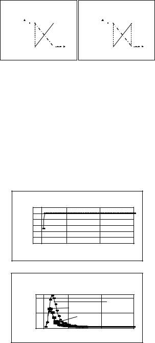
The simulations are organized around two different power transients:
a step-up in power from 5% to 10% (Figure 11);
a ramp-up in power from 5% to 10% (Figure 12)
The model horizon is T=200. Increasing Ny results in a more conservative control action that has a stabilizing effect but also increases the computational effort.
The computational effort increases as Nu is increased. A small value of Nu leads to a robust controller.
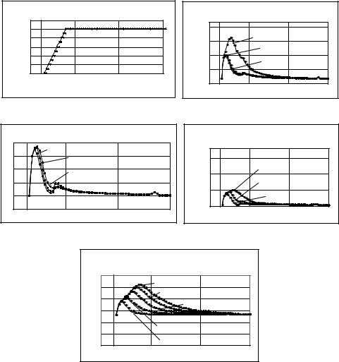
For both power transients the controller responses are very satisfactory and not very sensitive to changes in tuning parameters.
We can see that the performance is not strongly affected by the presence of the feed-water inverse response, only a slight oscillation is visible in the water level response.
Step power increase from 5% to 10%
|
|
|
|
[%] |
|
|
|
|
|
|
|
Power |
|
|
|
|
|
|
|
|
|
|
|
|
|
|
|
|
|
|
|
|
|
Time [sec] |
|
Water level response to a step power increase from 5% to 10%
Level |
|
|
|
|
|
|
|||
|
||||
|
|
|
|
|
|
|
|
|
Fig. 11. Water level response to a step power increase from 5% to 10% (Nu=2, Ny=3, W1=1)
32 |
Nuclear Power Plants |
Power [%]
|
Power ramp up from 55 to 10% |
|
|
Water level response to a power ramp up |
|
||
|
|
|
|
|
|
from 5% to 10% |
|
|
|
|
|
|
|
|
|
|
|
|
|
|
|
|
|
|
|
|
|
Level |
|
|
|
|
|
|
|
|
|
||
|
|
|
|
|
|
||
|
|
|
|
|
|
|
|
|
|
|
|
|
|
|
|
|
|
|
|
|
|
|
|
|
|
|
|
|
|
|
|
|
|
|
|
|
|
Time [sec] |
|
|
|
Time [sec] |
|
|
|
|
|
(a)
Level
|
Water level response to a power ramp up from 5% |
|
Water level response to a power ramp up |
|
||||||
|
|
to 10% |
|
|
|
|
|
|||
|
|
|
|
|
|
|
from 5% to 10% |
|
||
Nu=2 |
|
|
|
|
|
|
|
|
||
|
|
|
|
|
|
|
|
|
|
|
|
Nu=3 |
|
|
|
|
|
|
|
|
|
|
|
|
|
|
|
|
|
|
||
|
|
|
|
|
|
|
Level |
|
|
|
|
|
Nu=4 |
|
|
|
|
|
|
|
|
|
|
|
|
|
|
|
|
|
||
|
|
|
|
|
|
|
|
|
|
|
|
|
|
|
|
|
|
|
|
||
|
|
|
|
|
|
|
|
|
|
|
|
Time [sec] |
|
|
|
|
|
Time [sec] |
|
||
|
|
(b) |
|
|
|
|
|
|
(c) |
|
|
|
|
|
|
|
|||||
|
|
|
|
|
|
|
|
|
|
|
|
|
|
|
|
|
|
|
|
|
|
|
|
|
|
|
|
|
|
|
|
|
|
|
|
|
|
|
|
|
|
|
|
|
|
|
|
|
|
|
|
|
|
|
|
|
Level |
|
|
|
|
|
|
|
|
|
|
|
|
|
|
|
|
|
||
|
|
|
|
|
|
|
|
|
|
|
|
|
|
|
|
|
|
|
|
|
|
|
|
|
|
|
|
|
|
|
|
|
|
|
|
|
|
|
|
|
|
|
|
|
|
|
|
|
Time [sec] |
|
|
|||
|
|
|
|
|
|
|
|
|||
(d)
Fig. 12. Water level response. a) to power ramp up from 5% to 10% (Nu=2, Ny=3, W1=1); b) to power ramp up from 5% to 10% (W2=0.1, Ny=3, W1=1); c) to power ramp up from 5% to 10% (W2=0.1, Ny=7, W1=1); d) to power ramp up from 5% to 10% (W2=0.1, Ny=11, W1=1).
3.5 Evolved controller client/server architecture
An original concept of modular evolved control system, seamless and with gradual integration into the primary control system is proposed.
The aim of the application is to integrate the concepts of evolved control algorithms, portability of software modules, real time characteristics of the application.
Evolved Fuzzy Control System for a Steam Generator |
33 |
The target systems are the large scale distributed control systems with optimum granularity architecture.
The first part of the life cycle phases of the new control system, from conception to validation stage, the new control system lives “hiding in the shadow” of the control system it will replace, and after validation the old system will be replaced by the new one.
The identification, modeling, control and validation stages of the life cycle of the system, will be done on-line (the new system uses a real image of the I/O process data), without affecting the existing control system.
Because of high level of interconnectivity between system components, it is necessary to provide the highest independence between communication modules on one-hand and the control modules on the other hand. In order to obtain high ability of integration, the communication modules have to cover the widest possible area of industrial communication interfaces and protocols.
One item of the application is to offer a unified API of extended generality and extendibility in order to unify access and information retrieval from various wireless and wired technology and communication interfaces (RS 232, RS 485, fieldbus: Profibus / Interbus, Ethernet IP, TCP/IP, etc).
Applications could properly adapt to changes in the network connections.
The design and implementation of a solution to hide the embedded communication network problems from the application system programmers is included.
One of the main objectives of the application is to supply an integrated solution of systems, which should support all the phases of the life cycle: modeling, simulation, development and implementation.
For parameter tuning, for validation and also for embedding a large number of industrial communication protocols, multi-disciplinary simulation environments are developed which generate instruments for control, I/O data consistency check, and defect detection.
In the end, real-time advanced control applications are developed, with seamless and gradual integration into the existing distributed control system.
A software package for evolved control includes a method based on fuzzy model predictive control.
By using the basic concept of decomposition-coordination in a large-scale system theory, the fuzzy model predictive controller design can be accomplished through a two-layer iterative design process.
The design is decomposed into the derivation of local controllers. The subsystems regulated by those local controllers will be coordinated to derive a globally optimal control policy.
In order to provide the real-time characteristic, we choose a multitasking environment for the application (WINDOWS Operating System).
From structural point of view we propose a Client / Server architecture for fuzzy Controller (FC) (Andone et al., 2006):
Client - is a Windows application representing the implementation of the graphical user interface (GUI). The Client enables the operator to control the system in two modes:
34 |
Nuclear Power Plants |
manual/automatic, to monitor the system response, etc. The Client has also the ability to connect and communicate with the Server application.
Server – is an ActiveX EXE application containing the implementation of the Fuzzy Controller (FC) kernel.
The Server includes a collection of objects, these objects cover the tasks of both data processing and the communication between dedicated applications for input and output data.
The Client application will have a thread pool architecture.
The Server application will have a real multithreading architecture (each active object having assigned its own execution thread).
The Server have also a multi-layer structure: at the higher level are implemented upper FC and the communication classes (using different transmission mechanisms – DDE, OPC, HLI, ActiveX, Winsocket, Pipes), at the lower level are implemented the controllers for the subsystems corresponding to the low level FC.
The Server’s application as real multithreading architecture, provides the FC Kernel the realtime response characteristic, required for the industrial process control.
4. Conclusions
Control of SG water level strongly affects nuclear power plant availability.
The control task is difficult for a number of reasons, the most important among them being the nonlinear plant dynamics and the non-minimum phase plant characteristics.
There has been a special interest in this problem during low power transients because of the dominant reverse thermal dynamic effects known as shrink and swell.
The SG level control problem was viewed as a single input/single output control problem with the feed-water as the manipulated variable, the level as the controlled variable and the turbine steam demand as disturbance.
It has been shown that in the case of nonlinear processes, the approach using fuzzy predictive control gives very promising results.
The process non-linearity was addressed by scheduling the model (and the controller) with the power level.
The SG system is modeled by Takagi-Sugeno’s fuzzy modeling methodology, where the system output is estimated based on gradient. The complex shrink and swell phenomena associated with the SG water level are well captured by the model.
The predictive controller based on fuzzy model is designed in a hierarchical control design.
An original concept of modular evolved control system, seamless and gradual integration into the existing distributed control system is proposed in the chapter.
A unified API of extended generality and extendibility in order to unify access and information retrieval from various wireless and wired technology and communication interfaces is developed in order to ensure independence between communication and control modules of the designed systems.