

Chapter 17 |
|
DIESEL ENGINE: STAR SET-UP IN ES-ICE AND PRO-STAR |
||
|
|
|
STAR Set-up in pro-STAR |
|
|
|
|
|
|
|
scroll box at the bottom of the panel. The correspondence between injector |
|||
|
and coordinate system is summarised in Table 17-1. |
|||
|
Table 17-1: Injector number coordinate assignment |
|||
|
|
|
|
|
|
|
Injector Number |
Coordinate System |
|
|
|
|
|
|
|
|
2 |
Coordinate system 12 |
|
|
|
|
|
|
|
|
3 |
Coordinate system 13 |
|
|
|
|
|
|
|
|
4 |
Coordinate system 14 |
|
|
|
|
|
|
|
|
5 |
Coordinate system 15 |
|
|
|
|
|
|
|
|
6 |
Coordinate system 16 |
|
|
|
|
|
|
|
|
7 |
Coordinate system 17 |
|
|
|
|
|
|
|
|
8 |
Coordinate system 18 |
|
|
|
|
|
|
|
Setting up the Liquid Film Model |
|
|
|
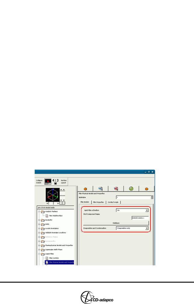
When fuel is sprayed into the cylinder, any fuel droplets that fall on the cylinder wall will generate a thin liquid film. To model this behaviour, activate the liquid film model, select the film physical properties and allow evaporation to take place.
•In the pro-STAR Model Guide, select Liquid Films > Film Physical Models and Properties (see Figure 17-18) and set the panel parameters as follows:
•Ensure that Liquid Film Activation is set to On
•Set the Evaporation and Condensation option to Evaporation only
•Click Database and select C12H26_l (DODECANE(L))
•Click Apply
Figure 17-18 Film Physical Models and Properties panel
Version 4.20 |
17-15 |
DIESEL ENGINE: STAR SET-UP IN ES-ICE AND PRO-STAR |
Chapter 17 |
STAR Set-up in pro-STAR |
|
|
|
Since this tutorial describes a closed-cycle case, there is only one solution domain (Material # 1) in the mode. You therefore only need to set properties for one film material.
Setting up Analysis Controls
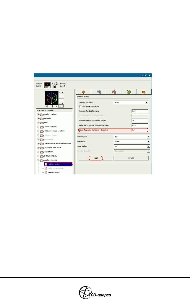
Specify solver solution controls and output parameters that enable post-processing of the results.
•In the pro-STAR Model Guide window, select Analysis Controls > Solution Method (see Figure 17-19) and set the panel parameters as follows:
•Set the Under Relaxation for Pressure Correction to 0.5
•Click Apply
Figure 17-19 Solution Method panel
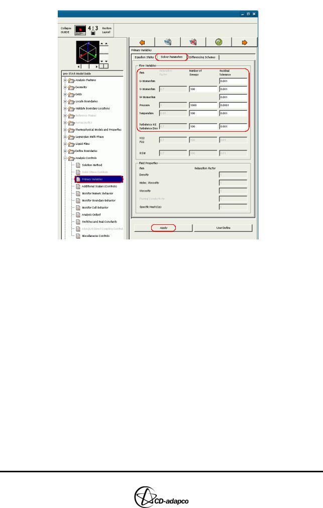
•In the Analysis Controls > Primary Variables panel, select the Solver Parameters tab (see Figure 17-20) and change the Residual Tolerance values as follows:
•Set all momentum residuals (U-Momentum, V-Momentum and
W-Momentum) to 0.001
•Set the Pressure to 0.0001
•Set the turbulence residuals (Turbulence KE and Turbulence Diss) to
0.001
•Click Apply
17-16 |
Version 4.20 |
Chapter 17 |
DIESEL ENGINE: STAR SET-UP IN ES-ICE AND PRO-STAR |
|
STAR Set-up in pro-STAR |
|
|
Figure 17-20 Primary Variables panel
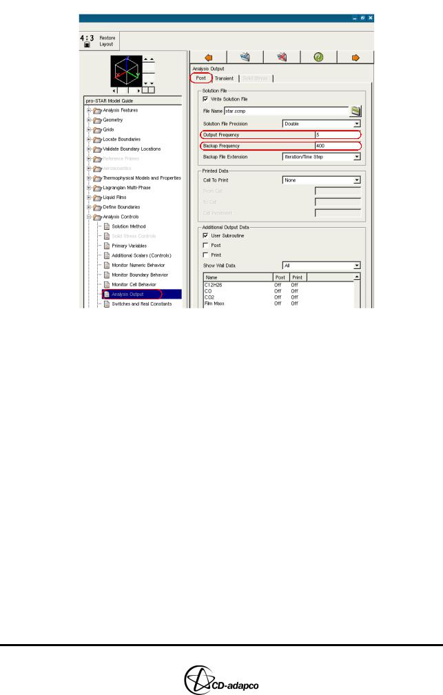
•In Analysis Controls > Analysis Output, select the Post tab (see Figure 17-21) and set the panel parameters as follows:
•Set the Output Frequency to 5
•Set the Backup Frequency to 400
•Click Apply
Version 4.20 |
17-17 |
DIESEL ENGINE: STAR SET-UP IN ES-ICE AND PRO-STAR |
Chapter 17 |
STAR Set-up in pro-STAR |
|
|
|
Figure 17-21 Post Analysis Output panel
•Select the Transient tab (see Figure 17-22) and set the panel parameters as follows:
•Set the Starting at time (degCA) to 680
•Set the Output interval (degCA) to 2
•In the displayed list of available output data, select Density and click the Post check box
•Repeat the previous step for the following variables:
•C12H26
•Dissipation
•Film Mass Fractions
•Temperature
•Turb Kinetic Energy
•Click Apply
17-18 |
Version 4.20 |