


Chapter 1 |
INTRODUCTION |
|
The es-ice Environment |
Chapter 1 INTRODUCTION
es-ice is a GUI package designed to facilitate moving-grid, transient analyses of internal combustion engines and is used in conjunction with CD-adapco’s pro-STAR and STAR products. es-ice can create grids for two, three, four or five-valve cylinders, generate the “events” input for pro-STAR and move the mesh during the STAR CFD analysis.
The strategy underlying this suite is straightforward. With es-ice, you can quickly and easily generate a template that approximates the desired geometry. The template has the connectivity of the final grid, but its shape is simple enough to be specified with a limited number of parameters. The template can be generated for a wide variety of configurations merely by altering these parameters. Where possible, es-ice provides graphical tools for setting the parameters so that minimal knowledge of parameter names is required. You can then either trim the template or map the surface of the template to the surface of the problem geometry. The interior vertices are then redistributed to form a mesh that correctly represents the desired geometry. After the model and analysis set-up is completed in pro-STAR, you are able to run the STAR solver and display the results via pro-STAR.
The chief benefits of this approach are:
• Quick generation of an approximate template
• Flexibility in grid design provided via parameterisation facilities
• Ease-of-use arising from the available graphical tools
• Time-saving gained from automatic smoothing of interior mesh vertices
• Automatic events generation and automatic mesh motion
• Use of STAR, a proven, reliable and accurate CFD solver
The entire es-ice, pro-STAR, STAR suite is fully capable of solving complete engine cycle problems and also of automatically preparing the necessary files for parallel computation.
Note that the actual engine models you can build using es-ice are generally not the same as the engine models used in this tutorial volume. Certain features in your own models may not be present in our tutorials, but the general methods of treating such features are described either in this volume or in the es-ice User Guide. You should not treat every step described in this volume as a general guideline that applies to all engine geometries.
You are also encouraged to read the User Guide documentation to help you gain a better understanding of how the code works.
The es-ice Environment
Two executables, es-ice and Ice, constitute the es-ice suite. You interact directly with es-ice, which provides a working environment through GUI panels, tools and windows. The Ice executable is called by es-ice or STAR and performs tasks such as generating meshes and computing vertex positions.
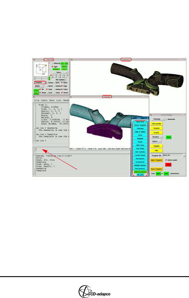
Several windows open when es-ice is launched, as illustrated in Figure 1-1. Separate plotting windows are dedicated to the geometry and template displays. The word “geometry” is used to represent the discretised surface defining the boundaries of the fluid domain available for the CFD calculation. The word “template” is used
Version 4.20 |
1-1 |
INTRODUCTION |
Chapter 1 |
The es-ice Environment |
|
|
|
to represent the computational mesh covering that domain. Therefore, the geometry is displayed in the Geometry window and the template in the Template window. The active window is indicated by a highlighted button in the Plot Tool, which is the panel lying in the upper-left corner of the screen. The appropriate button in this panel is used to toggle back and forth between the desired windows.
The Select panel provides access to the other GUI panels and tools (including on-line help) and is organised so that you pick tools sequentially during a typical es-ice session. Additional information about the es-ice environment can be found in Chapter 2 of the User Guide.
 es-ice Command Window
Figure 1-1 The es-ice environment
Most of the time, you will interact with the GUI interface using mouse buttons:
•Rotation via the Left mouse button “L”
•Panning via the Right mouse button “R”
•Zooming in and out via the Middle mouse button “M”
These actions are used extensively to view and analyse the geometry or the template. There is always text at the bottom of the active plotting window that shows the mouse functions available. Note that double letters (e.g. “LL”) represent a double-click and the “->” arrow represents a click and drag.
es-ice employs text-based “commands” to perform its operations and these can be executed by typing them in the es-ice command window. Some of them can also be executed by clicking a button in one of the GUI panels.
If an es-ice command or a series of commands are repeatedly used, you can manually create a GUI button that will execute the command. These custom buttons can be grouped together to form a user-defined panel. Detailed information on
1-2 |
Version 4.20 |
Chapter 1 |
INTRODUCTION |
|
es-ice Meshing Capabilities |
|
|
|
creating and opening a user-defined panel is given in Chapter 2, “User panels” of |
|
the User Guide. |
es-ice Meshing Capabilities
es-ice offers two methods for modeling internal combustion engines, called Mapping and Trimming. Both methods require you to build 2D and 3D templates that define a discretised representation of the engine geometry. The 3D template is then mapped or trimmed to obtain the shape of the domain used in the CFD analysis.
In the Mapping method, curves on the template, called edges, are mapped on corresponding curves on the geometry, called splines. Similarly, cell faces on the template, called patches, are mapped onto corresponding surfaces of the geometry. As the complexity of the geometry increases, the time required for the mapping process increases. In general the time to generate an engine mesh using the Mapping method is proportional to the complexity of the geometry.
The Trimming method on the other hand requires much less user intervention. In this case, the 3D template is cut by the engine geometry using the so-called trimmed mesher.
Two more special meshing methods are available for generating a mesh for the closed-cycle phase of an engine analysis (i.e. when all valves are closed):
•Closed-cycle polyhedral meshing is suitable for cylinder geometries that include valves recesses on the cylinder head and valve pockets on the piston crown. This method employs a combination of polyhedral cells and extruded cell layers, and can include an orthogonal mesh suitable for fuel spray modelling.
•Sector meshing is suitable for closed-cycle, axisymmetric engine cylinder problems.
Tutorial Structure
es-ice offers four meshing methods: Trimming, Mapping, Polyhedral and Sector. The Tutorials volume covers all four methods, with additional examples illustrating the use of various advanced features. This section indicates which chapters relate to particular es-ice features and provides general guidelines for working through the tutorials.
The main tutorial uses the Trimming method and a simple case set-up to illustrate the overall modelling process, from engine geometry import to post-processing the analysis results. We recommend that you first go through the chapters listed below before moving on to the advanced es-ice features:
•Chapter 2: Surface preparation in STAR-CCM+
•Chapter 3: Geometry import and valve work
•Chapter 4: Meshing with the Trimming method
•Chapter 5: Creating and checking the computational mesh.
•Chapter 6: STAR set-up in es-ice
•Chapter 7: STAR set-up in pro-STAR
•Chapter 8: Running the STAR solver
•Chapter 9: Post-processing: General techniques
•Chapter 10: Creating a mesh using the automatic 2D template
Version 4.20 |
1-3 |

INTRODUCTION |
Chapter 1 |
Trimming Tutorial Overview |
|
|
|
The examples in the following chapters employ advanced es-ice features and are used in addition to the trimming tutorial. The relevant files created for the trimming tutorial are specified at the start of each chapter:
•Chapter 11: Multiple-cycle analysis
•Chapter 12: Wall heat transfer analysis
•Chapter 13: Mesh replacement
•Chapter 14: Multiple cylinders
Chapters describing meshing for diesel engines are independent from the earlier chapters and deal with cases that also include fuel sprays:
•Chapter 15: Full-cylinder closed-cycle model
•Chapter 16: Diesel engine sector model
•Chapter 17: Model set-up in es-ice and pro-STAR
•Chapter 18: Post-processing Diesel models
The following chapter contains an independent tutorial describing the meshing and physics set-up for a two-stroke engine simulation:
•Chapter 19: Two-stroke engines
Examples illustrating the Mapping method as an alternative meshing process to Trimming are described in the chapters below, but the method is not recommended for general use.
•Chapter 20: Meshing with the Mapping method
•Chapter 21: Improving the Mapped mesh quality
•Chapter 22: Piston modeling
Once Chapter 20 to 22 are complete, use the examples in Chapter 5 to 9 as a guide for finishing the mapped mesh analysis.
Finally, Chapter 23 describes a case that uses the ECFM-CLEH combustion model in conjunction with the ELSA spray simulation model.
Trimming Tutorial Overview
The trimming example in this manual is a symmetric, four-valve cylinder of a gasoline engine. The surface mesh represents the +y half of the combustion dome, piston crown, ports/arms and valves and the model units are in millimetres. The geometry is oriented such that the piston travels in the +z direction during compression. The (x,y) coordinates of the cylinder centre are (0,0) and the combustion deck is at the z = 0 level. The piston is in the TDC position and the valves are in their respective closed positions. The intake valve is Valve 1 and the intake port arm features a siamese design. The exhaust valve is Valve 2 and the exhaust port arm is a separate design. Other features include angled valves, a piston crescent and a piston bowl with a deep spark plug penetrating into it.
The geometry surface is closed and different cell types are assigned to the combustion dome, piston, cylinder wall, each port arm and each valve. The complete geometry is stored under entry ID 1 in a pro-STAR database file called
geometry.dbs.
Valve lift files, vlift01.dat and vlift02.dat, are supplied and the lift is
1-4 |
Version 4.20 |