

Chapter 14 |
MULTIPLE CYLINDERS |
|
STAR Set-Up in es-ice |
|
|
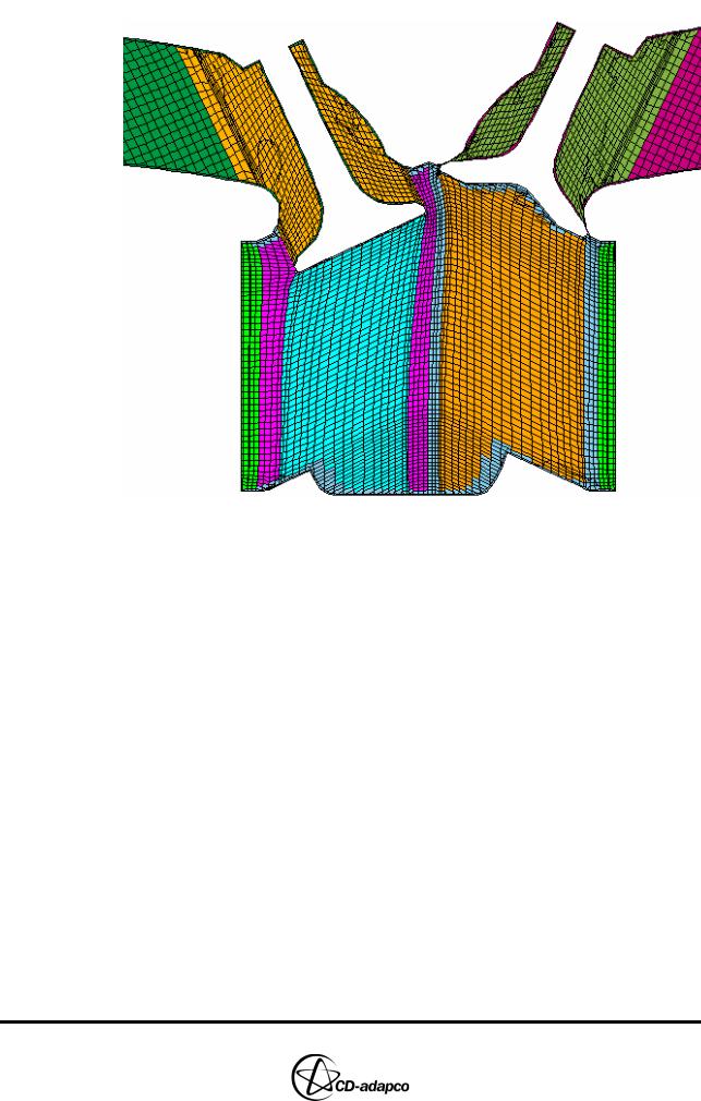
Figure 14-6 Section plot at 964 degrees crank angle
STAR Set-Up in es-ice
This section describes the Star Controls panel settings. It is assumed that you have gone through Chapter 6 of this volume and are familiar with using Star Controls. Therefore, most settings in this tutorial are described in brief, as the set-up is similar to the Trimming tutorial. However, where differences do occur, full and detailed information is provided.
The intake and exhaust manifold meshes for this case are supplied in a database file. When creating manifolds for your own cases, it is important to check that the cell faces at the manifold-port interface are spatially coincident within the default tolerance of 0.1. This tolerance ensures that es-ice can connect (“CP Match”) the two meshes using default parameters. You can specify the correct location of the interface between manifold and port meshes using local coordinate systems and the VList command for determining vertex positions. This information can then be used in STAR-CCM+ or third-party software to create a manifold volume mesh that is in the correct position relative to the engine cylinder.
The Wiebe heat release correlation is used in place of combustion modeling. Strictly speaking, the Wiebe correlation is not a combustion model as there is no reaction between scalars, no ignition and the flame propagation cannot be tracked. However, flow and heat release is simulated, so mixing, volumetric efficiency and engine performance can be analysed. Due to its simplicity, the Wiebe approach is suitable for meshes such as this containing large numbers of cells, as it can result in faster processing times.
Version 4.20 |
14-7 |
MULTIPLE CYLINDERS |
Chapter 14 |
STAR Set-Up in es-ice |
|
|
|
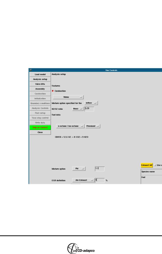
Analysis set-up
Using the Analysis setup view of the Star controls panel (see Figure 14-7), load the model and define a number of initial settings.
•Click Load model to load the es-ice model into the Controls Workspace window
•Select Wiebe from the combustion model drop-down menu
•Check that the fuel type is set to n-octane / iso-octane
•Set the Mixture option to Equivalence ratio and enter 1.3 for the air-fuel ratio
•Click the Premixed toggle button as fuel and air are mixed upstream of the intake port
•Set the EGR definition to Air+Exhaust and specify that 5% of the intake charge is recirculated exhaust gases
Figure 14-7 Multiple cylinder Star Controls > Analysis setup panel
Assembly
Use the Assembly view of the Star controls panel to import the intake and exhaust manifolds, as shown in Figure 14-8.
•Click the ellipsis (...) next to Database file and select manifoldTwin.dbs from the file browser
•Click the ellipsis (...) next to Database ID and select 1 Intake Manifold
•Click Get to load the intake manifold into the Controls Workspace window
14-8 |
Version 4.20 |
Chapter 14 |
MULTIPLE CYLINDERS |
|
STAR Set-Up in es-ice |
|
|
•Click the ellipsis (...) next to Database ID and select 2 Exhaust Manifold
•Click Get to load the exhaust manifold into the Controls Workspace window
Figure 14-8 Multiple cylinder Star Controls > Assembly panel
You can now create cell couples that join the intake and exhaust manifolds to the intake and exhaust ports.
•In the Plot Tool, deselect the Fill toggle button
•Click CPlot to re-display the cells in the Controls Workspace window
•In the Star Controls panel, select the Partial toggle button next to CP Match. Note that this option couples only part of the intake manifold to the intake port
•Click CP Match
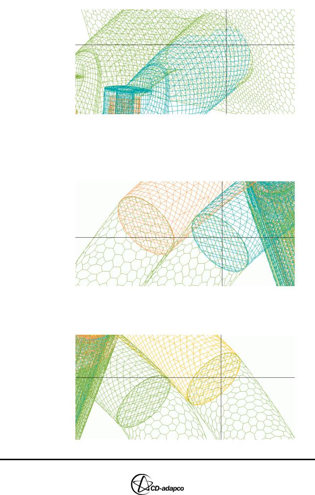
•In the Controls Workspace window, click on any interior cell face lying on the interface between the Intake Manifold and Cylinder 1 Intake Port, as shown in Figure 14-9
Figure 14-9 Interior face between the intake manifold and Cylinder 1’s intake port
•Click CP Match to create cell couples between the Intake Manifold and Cylinder 2 Intake Port, as shown in Figure 14-10
Version 4.20 |
14-9 |
MULTIPLE CYLINDERS |
Chapter 14 |
STAR Set-Up in es-ice |
|
|
|
Figure 14-10 Interior face between the intake manifold and Cylinder 2’s intake port
•Deselect the Partial toggle button for the exhaust manifold, as all its faces are coupled to the exhaust ports
•Click CP Match to create cell couples between the Exhaust Manifold and both the Cylinder 2 Exhaust Ports, as shown in Figure 14-11
Figure 14-11 Interior face between the exhaust manifold and Cylinder 2’s exhaust ports
•Click CP Match to create cell couples between the Exhaust Manifold and both the Cylinder 1 Exhaust Ports, as shown in Figure 14-12
Figure 14-12 Interior face between the exhaust manifold and Cylinder 1’s exhaust ports
14-10 |
Version 4.20 |