- •TABLE OF CONTENTS
- •Chapter 1 INTRODUCTION
- •The es-ice Environment
- •es-ice Meshing Capabilities
- •Tutorial Structure
- •Trimming Tutorial Overview
- •Required Files
- •Trimming Tutorial files
- •Automatic 2D Tutorial files
- •Wall Temperature Tutorial files
- •Mesh Replacement Tutorial files
- •Multiple Cylinder Tutorial files
- •Closed-Cycle Tutorial files
- •Sector Tutorial files
- •Two-Stroke Tutorial files
- •Mapping Tutorial files
- •ELSA Tutorial files
- •Chapter 2 SURFACE PREPARATION IN STAR-CCM+
- •Importing and Scaling the Geometry
- •Creating Features
- •Defining Surfaces
- •Remeshing and Exporting the Geometry
- •Chapter 3 GEOMETRY IMPORT AND VALVE WORK
- •Importing the Surfaces
- •Modelling the Valves
- •Saving the Model
- •Chapter 4 MESHING WITH THE TRIMMING METHOD
- •Modifying Special Cell Sets in the Geometry
- •Defining Flow Boundaries
- •Creating the 2D Base Template
- •Creating the 3D Template
- •Trimming the 3D Template to the Geometry
- •Improving cell connectivity
- •Assembling the Trimmed Template
- •Running Star Setup
- •Saving the Model
- •Chapter 5 CREATING AND CHECKING THE MESH
- •Chapter 6 STAR SET-UP in es-ice
- •Load Model
- •Analysis Set-up
- •Valve Lifts
- •Assembly
- •Combustion
- •Initialization
- •Cylinder
- •Port 1 and Port 2
- •Boundary Conditions
- •Cylinder
- •Port and Valve 1
- •Port and Valve 2
- •Global settings
- •Post Set-up
- •Cylinder
- •Port 1 and Port 2
- •Global settings
- •Time Step Control
- •Write Data
- •Saving the Model
- •Chapter 7 STAR SET-UP in pro-STAR
- •Using the es-ice Panel
- •Setting Solution and Output Controls
- •File Writing
- •Chapter 8 RUNNING THE STAR SOLVER
- •Running in Serial Mode
- •Running in Parallel Mode
- •Running in Parallel on Multiple Nodes
- •Running in Batch
- •Restarting the Analysis
- •Chapter 9 POST-PROCESSING: GENERAL TECHNIQUES
- •Creating Plots with the es-ice Graph Tool
- •Calculating Apparent Heat Release
- •Plotting an Indicator Diagram
- •Calculating Global Engine Quantities
- •Creating a Velocity Vector Display
- •Creating an Animation of Fuel Concentration
- •Creating an Animation of Temperature Isosurfaces
- •Chapter 10 USING THE AUTOMATIC 2D TEMPLATE
- •Importing the Geometry Surface
- •Defining Special Cell Sets in the Geometry
- •Modelling the Valves
- •Creating the Automatic 2D Template
- •Refining the 2D Template Around the Injector
- •Adding Features to the Automatic 2D Template
- •Using Detailed Automatic 2D Template Parameters
- •Saving the es-ice Model File
- •Chapter 11 MULTIPLE-CYCLE ANALYSIS
- •Setting Up Multiple Cycles in es-ice
- •Setting Up Multiple Cycles in pro-STAR
- •Chapter 12 HEAT TRANSFER ANALYSIS
- •Resuming the es-ice Model File
- •Mapping Wall Temperature
- •Exporting Wall Heat Transfer Data
- •Saving the es-ice Model File
- •Cycle-averaging Wall Heat Transfer Data
- •Post-processing Wall Heat Transfer Data in pro-STAR
- •Plotting average wall boundary temperatures
- •Plotting average heat transfer coefficients
- •Plotting average near-wall gas temperature at Y-plus=100
- •Mapping Heat Transfer Data to an Abaqus Model via STAR-CCM+
- •Chapter 13 MESH REPLACEMENT
- •Preparing the File Structure
- •Rebuilding the Dense Mesh
- •Creating Ahead Files for the Dense Mesh
- •Defining Mesh Replacements
- •Setting Up Mesh Replacement in pro-STAR
- •Setting up the coarse model
- •Setting up the dense model
- •Chapter 14 MULTIPLE CYLINDERS
- •Resuming the es-ice Model File
- •Making, Cutting and Assembling the Template
- •Setting Up Multiple Cylinders
- •Checking the Computational Mesh
- •STAR Set-Up in es-ice
- •Analysis set-up
- •Assembly
- •Combustion
- •Initialization
- •Boundary Conditions
- •Post Setup
- •Time Step Control
- •Write Data
- •Saving the es-ice Model File
- •Importing the Geometry
- •Generating the Closed-Cycle Polyhedral Mesh
- •Assigning shells to geometry cell sets
- •Specifying General, Events and Cylinder parameters
- •Creating a spray-optimised mesh zone
- •Importing a user intermediate surface
- •Checking the spray-optimised zone
- •Creating the closed-cycle polyhedral mesh
- •Running Star Setup
- •Creating and checking the computational mesh
- •Saving the Model File
- •Chapter 16 DIESEL ENGINE: SECTOR MODEL
- •Importing the Bowl Geometry
- •Defining the Bowl Shape
- •Defining the Fuel Injector
- •Creating the 2D Template
- •Creating the Sector Mesh
- •Creating and Checking the Mesh
- •Saving the Model
- •Chapter 17 DIESEL ENGINE: STAR SET-UP IN es-ice and pro-STAR
- •STAR Set-up in es-ice
- •Load model
- •Analysis setup
- •Assembly
- •Combustion
- •Initialization
- •Boundary conditions
- •Post setup
- •Time step control
- •Write data
- •Saving the Model File
- •STAR Set-up in pro-STAR
- •Using the es-ice Panel
- •Selecting Lagrangian and Liquid Film Modelling
- •Setting up the Fuel Injection Model
- •Setting up the Liquid Film Model
- •Setting up Analysis Controls
- •Writing the Geometry and Problem Files and Saving the Model
- •Chapter 18 DIESEL ENGINE: POST-PROCESSING
- •Creating a Scatter Plot
- •Creating a Spray Droplet Animation
- •Chapter 19 TWO-STROKE ENGINES
- •Importing the Geometry
- •Meshing with the Trimming Method
- •Assigning shells to geometry cell sets
- •Creating the 2D template
- •Creating the 3D template
- •Trimming the 3D template to the geometry
- •Assembling the trimmed template
- •Running Star Setup
- •Checking the mesh
- •STAR Set-up in es-ice
- •Analysis setup
- •Assembly
- •Combustion
- •Initialization
- •Boundary conditions
- •Post setup
- •Time step control
- •Write data
- •Saving the es-ice Model File
- •Chapter 20 MESHING WITH THE MAPPING METHOD
- •Creating the Stub Surface in the Geometry
- •Creating the 2D Base Template
- •Creating the 3D Template
- •General Notes About Edges and Splines
- •Creating Edges and Splines Near the Valve Seat
- •Creating the Remaining Edges and Splines
- •Creating Patches
- •The Mapping Process
- •Chapter 21 IMPROVING THE MAPPED MESH QUALITY
- •Creating Plastered Cells
- •Chapter 22 PISTON MODELING
- •Meshing the Piston with the Shape Piston Method
- •Chapter 23 ELSA SPRAY MODELLING
- •Importing the Bowl Geometry
- •Defining the Bowl Shape
- •Setting the Events and Cylinder Parameters
- •Creating the Spray Zone
- •Creating the Sector Mesh
- •STAR Set-up in es-ice
- •Load model
- •Analysis setup
- •Assembly
- •Combustion
- •Initialization
- •Boundary Conditions
- •Time step control
- •Write data
- •Saving the Model File
- •STAR Set-up in pro-STAR
- •Using the es-ice panel
- •Activating the Lagrangian model
- •Defining the ELSA scalars
- •Setting up the Lagrangian droplets
- •Defining boundary regions and boundary conditions
- •Setting up analysis controls
- •Adding extended data for the ELSA model
- •Writing the Geometry and Problem Files and Saving the Model
Chapter 6 |
STAR SET-UP IN ES-ICE |
Chapter 6 STAR SET-UP in es-ice
The model at the beginning of this chapter can be resumed from file: save_es-ice.3-starsetup
The following tutorial data files are used in this chapter:
TRIMMING_TUTORIALS/manifold.dbs
TRIMMING_TUTORIALS/cylinder-3600.dat
TRIMMING_TUTORIALS/intake-3600.dat
TRIMMING_TUTORIALS/exhaust-3600.dat
The model at the end of this chapter is saved to file: save_es-ice.4-final
es-ice is designed to set up and run moving mesh problems for engine simulation as quickly and efficiently as possible. For this reason, the Star Controls panel (initially implemented in es-ice version 2.00) is designed to minimise the additional information needed to set-up a CFD analysis via the pro-STAR interface.
The Star Controls panel will supply the following items:
•Modifications to valve lift profiles
•Further changes to Star Setup parameters (Engine RPM, Start (deg), Stop (deg))
•Modifications to cylinder compression ratio
•Addition of static meshes to the initially generated mesh (e.g. manifolds)
•Combustion model data, in particular:
•Fuel type
•Model calibration parameters
•Ignition timing and location
•Knock and soot models
•Initial conditions for the cylinder and ports:
•Velocity
•Pressure
•Temperature
•Turbulence
•Gas composition
•Boundary conditions for individual cylinder and port boundaries:
•Adiabatic, fixed and mapped temperature walls
•Flow rate
•Pressure
•Temperature
•Turbulence
•Gas composition
•Post-processing set-up
•Time step controls
•Special files needed for importing the model into pro-STAR
Version 4.20 |
6-1 |
STAR SET-UP IN ES-ICE |
Chapter 6 |
Load Model |
|
|
|
Load Model
The Load model view loads the model into the Controls Workspace window.
•Click Load model on the left of the Star Controls panel (see Figure 6-1)
•Click Load model
Figure 6-1 Star Controls panel: Load model view
Analysis Set-up
The Analysis setup view is used to specify preliminary combustion model settings and parameters that define the initial scalar composition. The mass fractions of these scalars are calculated when you go through the “Write Data” section at the end of this chapter.
To complete the Analysis setup stage for this tutorial:
•Click Analysis setup on the left of the Star Controls panel (see Figure 6-2)
•Check that the Combustion toggle button is selected so that you can include a combustion model in the problem set-up
•Set the combustion model to ECFM-3Z, spark
•Set the fuel type to n-octane / iso-octane and Premixed
•Set the Mixture option to Phi and enter 1.3 for the air-fuel ratio
•Set the EGR definition to Air+Exhaust and enter 5% in the adjacent box to specify that 5% of the intake charge is recirculated exhaust gas
6-2 |
Version 4.20 |
Chapter 6 |
STAR SET-UP IN ES-ICE |
|
Valve Lifts |
|
|
Figure 6-2 Star Controls panel: Analysis setup view
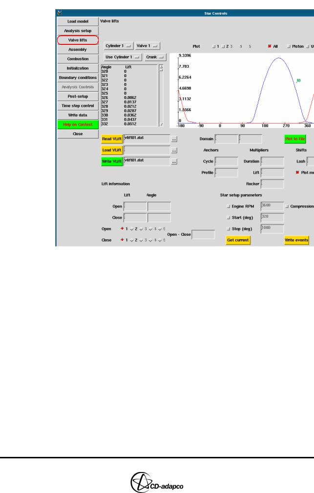
Valve Lifts
The Valve lifts view allows you to shift and modify the valve lift profile using anchors and multipliers. You can also adjust some of the Star Setup parameters and the compression ratio.
In this tutorial, no changes are required as the vlift01.dat and vlift02.dat files initially imported into the model in Chapter 4 are correctly set up.
To display the relevant data via the Valve lifts view:
•Click Valve lifts on the left of the Star Controls panel, as shown in Figure 6-3
Version 4.20 |
6-3 |
STAR SET-UP IN ES-ICE |
Chapter 6 |
Assembly |
|
|
|
Figure 6-3 Star Controls panel: Valve lifts view
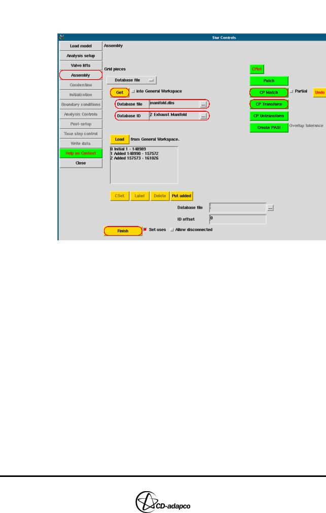
Assembly
The Assembly view allows you to add static meshes, such as manifolds and replacement ports, that need to be included in the overall model. In the following steps, you will add static meshes representing the intake and exhaust manifolds:
•Click Assembly on the left of the Star Controls panel (see Figure 6-4)
•Click the ellipsis (...) next to Database file and select manifold.dbs via the file browser
•Click the ellipsis (...) next to Database ID and select 1 Intake Manifold via the database browser
•Click Get to load the intake manifold into the Controls Workspace window
•Click the ellipsis (...) next to Database ID and select 2 Exhaust Manifold via the database browser
•Click Get to load the exhaust manifold into the Controls Workspace window
The es-ice output window will display the following commands:
IceTemplate, Controls, Pieces, DBRead, "manifold.dbs", 1
IceTemplate, Controls, Pieces, DBRead, "manifold.dbs", 2
These commands indicate that the intake manifold cells have been read into es-ice.
6-4 |
Version 4.20 |
Chapter 6 |
STAR SET-UP IN ES-ICE |
|
Assembly |
|
|
|
This part of the model is read into the Controls Workspace window by default if |
|
button into General Workspace is not selected. |
Figure 6-4 Star Controls panel: Assembly view
If you wish to perform additional mesh-change operations on any other part, use the General Workspace window. After making the required changes, click Load to load the current cell set from the General Workspace into the Controls Workspace window. All cells in the Controls Workspace window will form the version of the mesh that can be imported into pro-STAR.
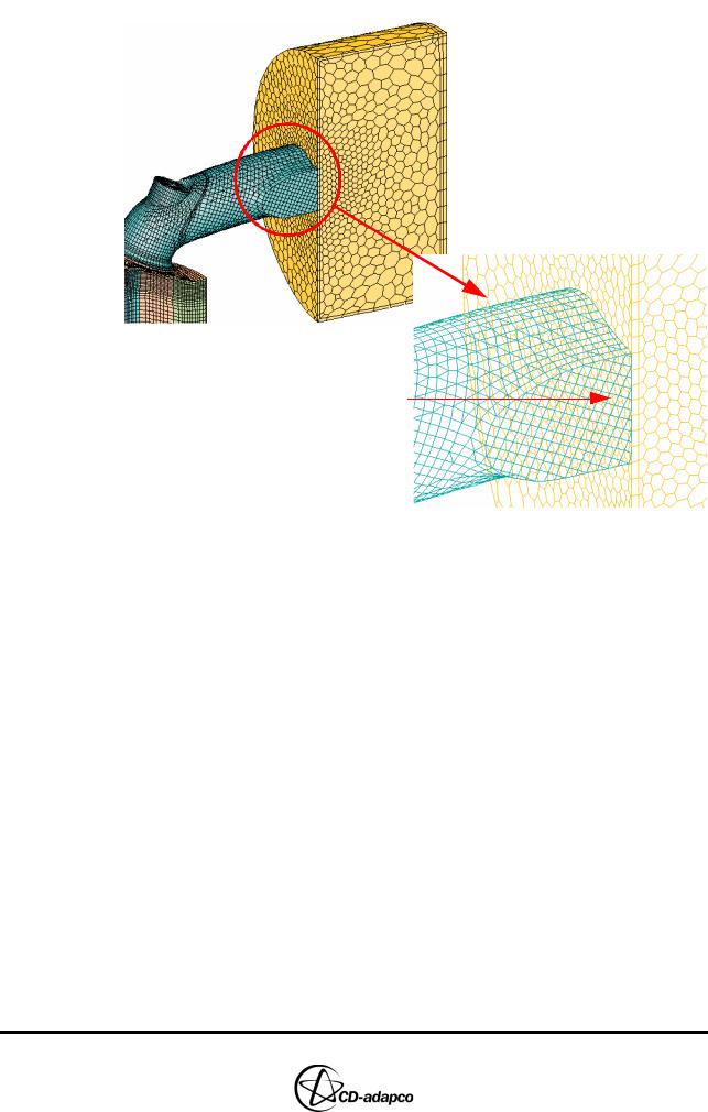
After the two manifolds are imported into the Controls Workspace window, create cell couples joining the ports to the manifolds:
•In the Plot Tool, deselect the Fill toggle button
•With the Controls Workspace window active, enter the following commands
CSet, All
CPlot
•In the Star Controls panel, select the Partial toggle button
•This option permits coupling of part of the intake manifold to the intake port (see Figure 6-5)
•Click CP Match
•In the Controls Workspace window, click an interior face, as shown in Figure 6-5
Version 4.20 |
6-5 |
STAR SET-UP IN ES-ICE |
Chapter 6 |
Assembly |
|
|
|
Interior Face
Figure 6-5 Creating cell couples
es-ice temporarily creates patches, then cell couples and then plots the new cell connectivity. If the cell couples are incorrectly defined, you can undo the coupling by clicking Undo. Note that the interior faces between these two bodies will disappear after you have successfully created the cell couples.
Continue to couple the manifolds to the ports as follows:
•In the Star Controls panel, deselect the Partial toggle button and click CP
Match
•In the Controls Workspace window, pick an interior face between the exhaust port and exhaust manifold
•In the Star Controls panel, click CP Transform to transform cells containing master/slave coupled cell faces into polyhedral cells
•CP Transform deletes the cell couples and replaces them with one-to-one connections between cell faces, as shown in Figure 6-6.
•Click Finish to finish defining cell connectivity and pro-STAR moving-mesh “events”
6-6 |
Version 4.20 |