- •TABLE OF CONTENTS
- •Chapter 1 INTRODUCTION
- •The es-ice Environment
- •es-ice Meshing Capabilities
- •Tutorial Structure
- •Trimming Tutorial Overview
- •Required Files
- •Trimming Tutorial files
- •Automatic 2D Tutorial files
- •Wall Temperature Tutorial files
- •Mesh Replacement Tutorial files
- •Multiple Cylinder Tutorial files
- •Closed-Cycle Tutorial files
- •Sector Tutorial files
- •Two-Stroke Tutorial files
- •Mapping Tutorial files
- •ELSA Tutorial files
- •Chapter 2 SURFACE PREPARATION IN STAR-CCM+
- •Importing and Scaling the Geometry
- •Creating Features
- •Defining Surfaces
- •Remeshing and Exporting the Geometry
- •Chapter 3 GEOMETRY IMPORT AND VALVE WORK
- •Importing the Surfaces
- •Modelling the Valves
- •Saving the Model
- •Chapter 4 MESHING WITH THE TRIMMING METHOD
- •Modifying Special Cell Sets in the Geometry
- •Defining Flow Boundaries
- •Creating the 2D Base Template
- •Creating the 3D Template
- •Trimming the 3D Template to the Geometry
- •Improving cell connectivity
- •Assembling the Trimmed Template
- •Running Star Setup
- •Saving the Model
- •Chapter 5 CREATING AND CHECKING THE MESH
- •Chapter 6 STAR SET-UP in es-ice
- •Load Model
- •Analysis Set-up
- •Valve Lifts
- •Assembly
- •Combustion
- •Initialization
- •Cylinder
- •Port 1 and Port 2
- •Boundary Conditions
- •Cylinder
- •Port and Valve 1
- •Port and Valve 2
- •Global settings
- •Post Set-up
- •Cylinder
- •Port 1 and Port 2
- •Global settings
- •Time Step Control
- •Write Data
- •Saving the Model
- •Chapter 7 STAR SET-UP in pro-STAR
- •Using the es-ice Panel
- •Setting Solution and Output Controls
- •File Writing
- •Chapter 8 RUNNING THE STAR SOLVER
- •Running in Serial Mode
- •Running in Parallel Mode
- •Running in Parallel on Multiple Nodes
- •Running in Batch
- •Restarting the Analysis
- •Chapter 9 POST-PROCESSING: GENERAL TECHNIQUES
- •Creating Plots with the es-ice Graph Tool
- •Calculating Apparent Heat Release
- •Plotting an Indicator Diagram
- •Calculating Global Engine Quantities
- •Creating a Velocity Vector Display
- •Creating an Animation of Fuel Concentration
- •Creating an Animation of Temperature Isosurfaces
- •Chapter 10 USING THE AUTOMATIC 2D TEMPLATE
- •Importing the Geometry Surface
- •Defining Special Cell Sets in the Geometry
- •Modelling the Valves
- •Creating the Automatic 2D Template
- •Refining the 2D Template Around the Injector
- •Adding Features to the Automatic 2D Template
- •Using Detailed Automatic 2D Template Parameters
- •Saving the es-ice Model File
- •Chapter 11 MULTIPLE-CYCLE ANALYSIS
- •Setting Up Multiple Cycles in es-ice
- •Setting Up Multiple Cycles in pro-STAR
- •Chapter 12 HEAT TRANSFER ANALYSIS
- •Resuming the es-ice Model File
- •Mapping Wall Temperature
- •Exporting Wall Heat Transfer Data
- •Saving the es-ice Model File
- •Cycle-averaging Wall Heat Transfer Data
- •Post-processing Wall Heat Transfer Data in pro-STAR
- •Plotting average wall boundary temperatures
- •Plotting average heat transfer coefficients
- •Plotting average near-wall gas temperature at Y-plus=100
- •Mapping Heat Transfer Data to an Abaqus Model via STAR-CCM+
- •Chapter 13 MESH REPLACEMENT
- •Preparing the File Structure
- •Rebuilding the Dense Mesh
- •Creating Ahead Files for the Dense Mesh
- •Defining Mesh Replacements
- •Setting Up Mesh Replacement in pro-STAR
- •Setting up the coarse model
- •Setting up the dense model
- •Chapter 14 MULTIPLE CYLINDERS
- •Resuming the es-ice Model File
- •Making, Cutting and Assembling the Template
- •Setting Up Multiple Cylinders
- •Checking the Computational Mesh
- •STAR Set-Up in es-ice
- •Analysis set-up
- •Assembly
- •Combustion
- •Initialization
- •Boundary Conditions
- •Post Setup
- •Time Step Control
- •Write Data
- •Saving the es-ice Model File
- •Importing the Geometry
- •Generating the Closed-Cycle Polyhedral Mesh
- •Assigning shells to geometry cell sets
- •Specifying General, Events and Cylinder parameters
- •Creating a spray-optimised mesh zone
- •Importing a user intermediate surface
- •Checking the spray-optimised zone
- •Creating the closed-cycle polyhedral mesh
- •Running Star Setup
- •Creating and checking the computational mesh
- •Saving the Model File
- •Chapter 16 DIESEL ENGINE: SECTOR MODEL
- •Importing the Bowl Geometry
- •Defining the Bowl Shape
- •Defining the Fuel Injector
- •Creating the 2D Template
- •Creating the Sector Mesh
- •Creating and Checking the Mesh
- •Saving the Model
- •Chapter 17 DIESEL ENGINE: STAR SET-UP IN es-ice and pro-STAR
- •STAR Set-up in es-ice
- •Load model
- •Analysis setup
- •Assembly
- •Combustion
- •Initialization
- •Boundary conditions
- •Post setup
- •Time step control
- •Write data
- •Saving the Model File
- •STAR Set-up in pro-STAR
- •Using the es-ice Panel
- •Selecting Lagrangian and Liquid Film Modelling
- •Setting up the Fuel Injection Model
- •Setting up the Liquid Film Model
- •Setting up Analysis Controls
- •Writing the Geometry and Problem Files and Saving the Model
- •Chapter 18 DIESEL ENGINE: POST-PROCESSING
- •Creating a Scatter Plot
- •Creating a Spray Droplet Animation
- •Chapter 19 TWO-STROKE ENGINES
- •Importing the Geometry
- •Meshing with the Trimming Method
- •Assigning shells to geometry cell sets
- •Creating the 2D template
- •Creating the 3D template
- •Trimming the 3D template to the geometry
- •Assembling the trimmed template
- •Running Star Setup
- •Checking the mesh
- •STAR Set-up in es-ice
- •Analysis setup
- •Assembly
- •Combustion
- •Initialization
- •Boundary conditions
- •Post setup
- •Time step control
- •Write data
- •Saving the es-ice Model File
- •Chapter 20 MESHING WITH THE MAPPING METHOD
- •Creating the Stub Surface in the Geometry
- •Creating the 2D Base Template
- •Creating the 3D Template
- •General Notes About Edges and Splines
- •Creating Edges and Splines Near the Valve Seat
- •Creating the Remaining Edges and Splines
- •Creating Patches
- •The Mapping Process
- •Chapter 21 IMPROVING THE MAPPED MESH QUALITY
- •Creating Plastered Cells
- •Chapter 22 PISTON MODELING
- •Meshing the Piston with the Shape Piston Method
- •Chapter 23 ELSA SPRAY MODELLING
- •Importing the Bowl Geometry
- •Defining the Bowl Shape
- •Setting the Events and Cylinder Parameters
- •Creating the Spray Zone
- •Creating the Sector Mesh
- •STAR Set-up in es-ice
- •Load model
- •Analysis setup
- •Assembly
- •Combustion
- •Initialization
- •Boundary Conditions
- •Time step control
- •Write data
- •Saving the Model File
- •STAR Set-up in pro-STAR
- •Using the es-ice panel
- •Activating the Lagrangian model
- •Defining the ELSA scalars
- •Setting up the Lagrangian droplets
- •Defining boundary regions and boundary conditions
- •Setting up analysis controls
- •Adding extended data for the ELSA model
- •Writing the Geometry and Problem Files and Saving the Model
Chapter 12 |
HEAT TRANSFER ANALYSIS |
|
Mapping Heat Transfer Data to an Abaqus Model via STAR-CCM+ |
|
|
Mapping Heat Transfer Data to an Abaqus Model via STAR-CCM+
In the final section of this tutorial, you will map the heat transfer data obtained from the es-ice simulation to an Abaqus model using the data mapping facilities of STAR-CCM+ v8.02. You will then proceed to import the updated solid model into Abaqus and run a thermal calculation.
To convert the heat transfer data from binary to coded format:
•In pro-STAR, enter the following command to read in the surface mesh and binary-format data:
DBASE, OPEN, intermediate_bnd.dbs DBASE, GET, 1
GETUSERDATA, cycle_avg1.usr, CELL, ALL, BINARY $ $
•Enter the following command to save the data in a coded-format file:
SAVUSERDATA, cycle_avg1_coded.usr, ALL, CODED, ALL
•Close pro-STAR without saving the model file
To import the es-ice CAE model and data:
•Launch STAR-CCM+ in the usual manner and start a new simulation
•From the menu bar, select File > Import > Import CAE Model
•In the Open panel, select intermediate_bnd.dbs and click Open
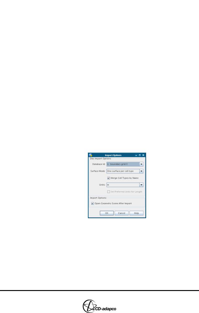
•In the Import Options panel, accept the default options and click OK as shown in Figure 12-14
Figure 12-14 es-ice CAE model import options
•Rightclick the Imported Model > Dbs: intermediate_bnd node and select
Import CAE Solution Data
•In the Open panel, select cycle_avg1_coded.usr and click Open
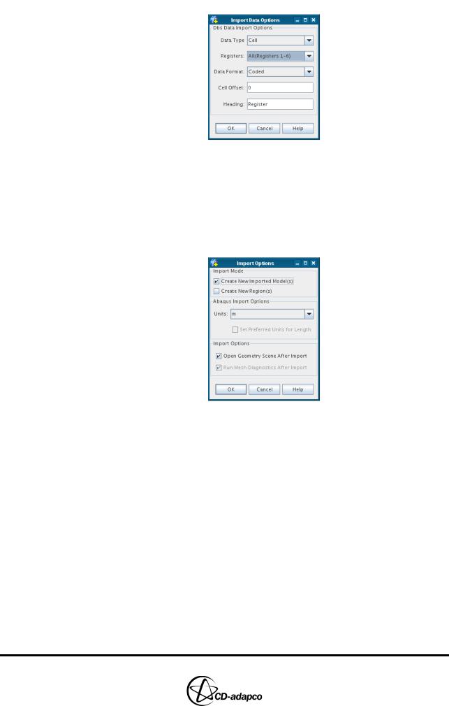
•In the Import Data Options panel, set Registers to All(Registers 1-6) and click OK as shown in Figure 12-15
Version 4.20 |
12-15 |
HEAT TRANSFER ANALYSIS |
Chapter 12 |
Mapping Heat Transfer Data to an Abaqus Model via STAR-CCM+ |
|
|
|
Figure 12-15 es-ice CAE solution data import options
To import the Abaqus CAE model:
•From the menu bar, select File > Import > Import CAE Model
•In the Open panel, select engine.inp and click Open
•In the Import Options panel, accept the default options and click OK as shown in Figure 12-16
Figure 12-16 Abaqus model import options
To map the es-ice heat transfer data to the Abaqus model:
•Right-click the Tools > Data Mappers node and select New Data Mapper >
Surface Data Mapper
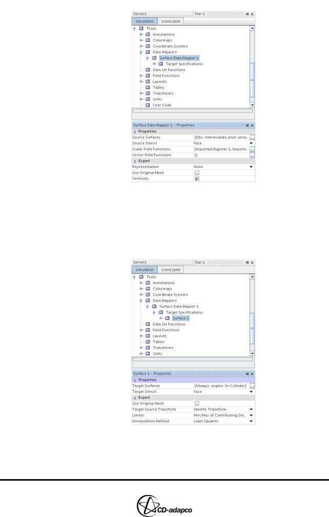
•Select the Data Mappers > Surface Data Mapper 1 node and set the properties as follows (see Figure 12-17):
•Source Surfaces: Imported Models > Dbs: intermediate_bnd > unnamed
•Source Stencil: Face
•Scalar Field Functions: Imported Register 1 and Imported Register 2
12-16 |
Version 4.20 |
Chapter 12 |
HEAT TRANSFER ANALYSIS |
|
Mapping Heat Transfer Data to an Abaqus Model via STAR-CCM+ |
|
|
Figure 12-17 Surface data mapper properties
•Select the Target Specifications > Surface 1 node and set the properties as follows (see Figure 12-18):
•Target Surface: Imported Surfaces > Abaqus: engine > In-Cylinder
•Target Stencil: Face
Figure 12-18 Target specification properties
•Right-click the Data Mappers > Surface Data Mapper 1 node and select
Map Data
Version 4.20 |
12-17 |
HEAT TRANSFER ANALYSIS |
Chapter 12 |
Mapping Heat Transfer Data to an Abaqus Model via STAR-CCM+ |
|
|
|
To export the mapped data:
•Right-click the Imported Models > Abaqus: engine node and select Export
Mapped Data to External File
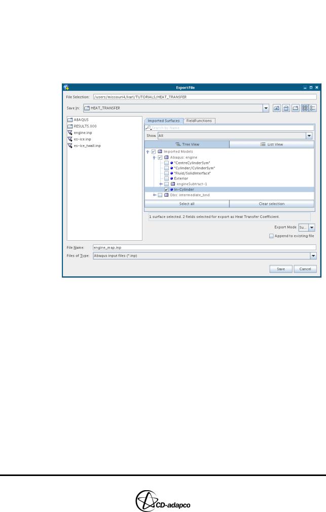
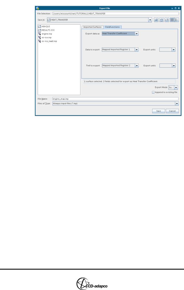
•In the Export File panel, set File Name to engine_map.inp
•In the Imported Surface tab (see Figure 12-19), select the Imported Models > Abaqus: engine > In-Cylinder node
Figure 12-19 Export selected surfaces
•In the Field Functions tab (see Figure 12-20), set Export data as to Heat
Transfer Coefficient
•Set Data to export to Mapped Imported Register 1 and Tref to export to
Mapped Imported Register 2
12-18 |
Version 4.20 |
Chapter 12 |
HEAT TRANSFER ANALYSIS |
|
Mapping Heat Transfer Data to an Abaqus Model via STAR-CCM+ |
|
|
Figure 12-20 Export selected field functions
•Click Save
To import the model with the mapped heat transfer data:
•With a text editor, edit the end of the engine.inp file as shown below:
•Before:
*Output, history *Contact Output
HFLA, HTL, HTLA, SJD, SJDA, SJDT, SJDTA, WEIGHT *Radiation Output
FTEMP, RADFL, RADFLA, RADTL, RADTLA, VFTOT *End Step
•After:
*Output, history *Contact Output
HFLA, HTL, HTLA, SJD, SJDA, SJDT, SJDTA, WEIGHT *Radiation Output
FTEMP, RADFL, RADFLA, RADTL, RADTLA, VFTOT
**
*Include,input=engine_map.inp
**
*End Step
•Save the file as engine_mod.inp
Version 4.20 |
12-19 |
HEAT TRANSFER ANALYSIS |
Chapter 12 |
Mapping Heat Transfer Data to an Abaqus Model via STAR-CCM+ |
|
|
|
To load the model and mapped heat transfer data into Abaqus:
•Launch Abaqus CAE in the usual manner
•From the menu bar, select File > Import > Model
•In the Import Model panel, select engine_mod.inp and click OK
12-20 |
Version 4.20 |