

Action Port
condition of case[1] was not previously false. The same applies to B.
Command-Line Information
Parameter: InitializeStates
Type: string
Value: 'held' | 'reset' |
Default: 'held'
2-13

Action Port
Propagate sizes of variable-size signals
Specify when to propagate a variable-size signal.
Settings
Default: Only when execution is resumed
Only when execution is resumed
Propagates variable-size signals only when reenabling the subsystem containing the Action Port block.
During execution
Propagates variable-size signals at each time step.
Command-Line Information
Parameter: PropagateVarSize
Type: string
Value: 'Only when execution is resumed' | 'During
execution'
Default: 'Only when execution is resumed'
Characteristics |
Sample Time |
Inherited from driving If or Switch Case |
|
|
block |
See Also If, If Action Subsystem, Switch Case, and Switch Case Action Subsystem blocks for examples using Action Port blocks
2-14

Algebraic Constraint
Purpose |
Constrain input signal to zero |
Library |
Math Operations |
Description |
|
Algorithm
Data Type
Support
The Algebraic Constraint block constrains the input signal f(z) to zero and outputs an algebraic state z. The block outputs the value that produces a zero at the input. The output must affect the input
through a direct feedback path, that is, the feedback path contains only blocks with direct feedthrough. For example, you can specify algebraic equations for index 1 differential-algebraic systems (DAEs).
The Algebraic Constraint block uses a dogleg trust-region algorithm to solve algebraic loops [1], [2].
The Algebraic Constraint block accepts and outputs real values of type double.
2-15

Algebraic Constraint
Parameters and Dialog Box
Example
Initial guess
An initial guess for the solution value. The default is 0.
By default, the Initial guess parameter is zero. You can improve the efficiency of the algebraic-loop solver by providing an Initial guess for the algebraic state z that is close to the solution value.
For example, the following model solves these equations:
z2 + z1 = 1
z2 - z1 = 1
The solution is z2 = 1, z1 = 0, as the Display blocks show.
2-16

Algebraic Constraint
Characteristics |
Direct Feedthrough |
Yes |
|
Sample Time |
Inherited from driving block |
|
Scalar Expansion |
No |
|
Dimensionalized |
Yes |
|
Zero-Crossing Detection |
No |
|
|
|
References [1] Garbow, B. S., K. E. Hillstrom, and J. J. Moré. User Guide for MINPACK-1. Argonne, IL: Argonne National Laboratory, 1980.
[2] Rabinowitz, P. H. Numerical Methods for Nonlinear Algebraic Equations. New York, NY: Gordon and Breach, 1970.
2-17

Assertion
Purpose |
Check whether signal is zero |
Library |
Model Verification |
Description |
The Assertion block checks whether any of the elements of the input |
|
signal is zero. If all elements are nonzero, the block does nothing. If any |
|
element is zero, the block halts the simulation, by default, and displays |
|
an error message. Use the block parameter dialog box to: |
|
• Specify that the block should display an error message when the |
|
assertion fails but allow the simulation to continue. |
|
• Specify a MATLAB expression to evaluate when the assertion fails. |
|
• Enable or disable the assertion. |
|
You can also use the Model Verification block enabling setting on |
|
the Data Validity diagnostics pane of the Configuration Parameters |
|
dialog box to enable or disable all Assertion blocks in a model. |
|
The Assertion block and its companion blocks in the Model Verification |
|
library are intended to facilitate creation of self-validating models. For |
|
example, you can use model verification blocks to test that signals do |
|
not exceed specified limits during simulation. When you are satisfied |
|
that a model is correct, you can turn error checking off by disabling the |
|
verification blocks. You do not have to physically remove them from the |
|
model. If you need to modify a model, you can temporarily turn the |
|
verification blocks back on to ensure that your changes do not break |
|
the model. |
|
|
|
Note For information about how Simulink Coder™ generated code |
|
handles Model Verification blocks, see “Debug”. |
Data Type |
The Assertion block accepts input signals of any dimensions and any |
Support |
numeric data type that Simulink supports, including fixed-point data |
|
types. |
2-18

Assertion
Parameters and Dialog Box
For more information, see “Data Types Supported by Simulink” in the Simulink documentation.
Enable assertion
Clearing this check box disables the Assertion block, that is, causes the model to behave as if the Assertion block did not exist. The Model Verification block enabling setting under
Debugging on the Data Validity diagnostics pane of the Configuration Parameters dialog box lets you enable or disable all Assertion blocks in a model regardless of the setting of this option.
2-19

Assertion
Simulation callback when assertion fails
Specify a MATLAB expression to evaluate when the assertion fails. Because the expression is evaluated in the MATLAB workspace, define all variables used in the expression in that workspace.
Stop simulation when assertion fails
Selecting this check box causes the Assertion block to halt the simulation when the block input is zero and display an error message in the Simulation Diagnostics Viewer. Otherwise, the block displays a warning message in the MATLAB Command Window and continues the simulation.
Sample time (-1 for inherited)
Enter the time interval between sample time hits or specify another appropriate sample time such as continuous. By default, the block inherits its sample time based upon its context within the model. For more information, see “Sample Time”.
Characteristics |
Direct Feedthrough |
No |
|
Sample Time |
Specified in the Sample time parameter |
|
Scalar Expansion |
No |
|
Dimensionalized |
Yes |
|
Multidimensionalized |
Yes |
|
Zero-Crossing Detection |
No |
|
|
|
2-20

Assignment
Purpose |
Assign values to specified elements of signal |
Library |
Math Operations |
Description |
|
The Assignment block assigns values to specified elements of the signal. You can specify the indices of the elements to be assigned values either by entering the indices in the block’s dialog box or by connecting an external indices source or sources to the block. The signal at the block’s data port, labeled U, specifies values to be assigned to Y. The block replaces the specified elements of Y with elements from the data signal.
Based on the value you enter for the Number of output dimensions parameter, a table of index options is displayed. Each row of the table corresponds to one of the output dimensions in Number of output dimensions. For each dimension, you can define the elements of the signal to work with. Specify a vector signal as a 1-D signal and a matrix signal as a 2-D signal. When you configure the Assignment block for multidimensional signal operations, the block icon changes.
For example, assume a 5-D signal with a one-based index mode. The table in the Assignment block dialog changes to include one row for each dimension. If you define each dimension with the following entries:
•1
Index Option, select Assign all
•2
Index Option, select Index vector (dialog)
Index, enter [1 3 5]
2-21

Assignment
•3
Index Option, select Starting index (dialog)
Index, enter 4
•4
Index Option, select Starting index (port)
•5
Index Option, select Index vector (port)
The assigned values will be Y(1:end,[1 3
5],4:3+size(U,3),Idx4:Idx4+size(U,4)-1,Idx5)=U, where Idx4 and Idx5 are the input ports for dimensions 4 and 5.
The Assignment block’s data port is labeled U. The rest of this section refers to the data port as U to simplify the explanation of the block’s usage.
You can use the block to assign values to vector, matrix, or multidimensional signals.
You can use an array of buses as an input signal to an Assignment block. For details about defining and using an array of buses, see “Combine Buses into an Array of Buses”.
Iterated Assignment
You can use the Assignment block to assign values computed in a For or While Iterator loop to successive elements of a vector, matrix, or multidimensional signal in a single time step. For example, the following model uses a For Iterator block to create a vector signal each of whose elements equals 3*i where i is the index of the element.
2-22
Assignment
Data Type
Support
Iterated assignment uses an iterator (For or While) block to generate indices for the Assignment block. On the first iteration of an iterated assignment, the Assignment block copies the first input (Y0) to the output (Y) and assigns the second input (U) to the output Y(E1). On successive iterations, the Assignment block assigns the current value of U to Y(Ei), that is, without first copying Y0 to Y. These actions occur in a single time step.
The data and initialization ports of the Assignment block accept signals of any data type that Simulink supports, including fixed-point and enumerated data types. The external indices port accepts any built-in data type, except Boolean data types.
For more information, see “Data Types Supported by Simulink” in the Simulink documentation.
2-23

Assignment
Parameters and Dialog Box
Number of output dimensions
Enter the number of dimensions of the output signal.
Index mode
Select the indexing mode: One-based or Zero-based. If One-based is selected, an index of 1 specifies the first element of the input vector, 2, the second element, and so on. If Zero-based is selected, an index of 0 specifies the first element of the input vector, 1, the second element, and so on.
2-24

Assignment
Index Option
Define, by dimension, how the elements of the signal are to be indexed. From the list, select:
•Assign all
This is the default. All elements are assigned.
•Index vector (dialog)
Enables the Index column. Enter the indices of elements.
•Index vector (port)
Disables the Index column. The index port defines the indices of elements.
•Starting index (dialog)
Enables the Index column. Enter the starting index of the range of elements to be assigned values.
•Starting index (port)
Disables the Index column. The index port defines the starting index of the range of elements to be assigned values.
If you choose Index vector (port) or Starting index (port) for any dimension in the table, you can specify the value for the Initialize output (Y) parameter to be one of the following:
•Initialize using input port <Y0>
•Specify size for each dimension in table
Otherwise, Y0 always initializes output port Y.
The Index and Output Size columns are displayed as relevant.
Index
If the Index Option is Index vector (dialog), enter the index of each element you are interested in.
2-25

Assignment
If the Index Option is Starting index (dialog), enter the starting index of the range of elements to be selected. The number of elements from the starting point is determined by the size of this dimension at U.
Output Size
Enter the width of the block output signal. If you select Specify size for each dimension in table for the Initialize output
(Y) parameter, this column is enabled.
Initialize output (Y)
Specify how to initialize the output signal. The Initialize output parameter appears when you set Index Option to Index vector
(port) or Starting index (port).
•Initialize using input port <Y0>
The signal at the input port Y0 initializes the output.
•Specify size for each dimension in table
The block requires you to specify the width of the block’s output signal in the Output Size parameter. If the output has unassigned elements, the value of those elements is undefined.
Action if any output element is not assigned
Specify whether to produce a warning or error if you have not assigned all output elements. Options include:
•Error
•Warning
•None
Sample time (-1 for inherited)
Specify the time interval between samples. To inherit the sample time, set this parameter to -1. See “Specify Sample Time” in the Simulink documentation.
2-26

Assignment
Characteristics |
Direct Feedthrough |
Yes |
|
Sample Time |
Specified in the Sample time parameter |
|
Scalar Expansion |
Yes |
|
Dimensionalized |
Yes |
|
Multidimensionalized |
Yes |
|
Zero-Crossing Detection |
No |
|
|
|
2-27

Backlash
Purpose |
Model behavior of system with play |
Library Discontinuities
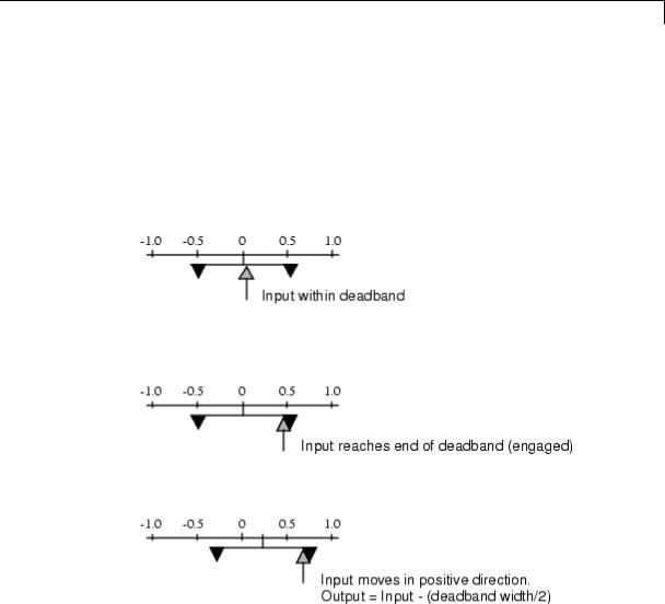
Description The Backlash block implements a system in which a change in input causes an equal change in output. However, when the input changes direction, an initial change in input has no effect on the output. The amount of side-to-side play in the system is referred to as the deadband. The deadband is centered about the output. This figure shows the block’s initial state, with the default deadband width of 1 and initial output of 0.
A system with play can be in one of three modes:
•Disengaged — In this mode, the input does not drive the output and the output remains constant.
•Engaged in a positive direction — In this mode, the input is increasing (has a positive slope) and the output is equal to the input minus half the deadband width.
•Engaged in a negative direction — In this mode, the input is decreasing (has a negative slope) and the output is equal to the input plus half the deadband width.
If the initial input is outside the deadband, the Initial output parameter value determines whether the block is engaged in a positive or negative direction, and the output at the start of the simulation is the input plus or minus half the deadband width.
For example, the Backlash block can be used to model the meshing of two gears. The input and output are both shafts with a gear on one end, and the output shaft is driven by the input shaft. Extra space
2-28
Backlash
between the gear teeth introduces play. The width of this spacing is the Deadband width parameter. If the system is disengaged initially, the output (the position of the driven gear) is defined by the Initial output parameter.
The following figures illustrate the block’s operation when the initial input is within the deadband. The first figure shows the relationship between the input and the output while the system is in disengaged mode (and the default parameter values are not changed).
The next figure shows the state of the block when the input has reached the end of the deadband and engaged the output. The output remains at its previous value.
The final figure shows how a change in input affects the output while they are engaged.
If the input reverses its direction, it disengages from the output. The output remains constant until the input either reaches the opposite end of the deadband or reverses its direction again and engages at the same end of the deadband. Now, as before, movement in the input causes equal movement in the output.
2-29

Backlash
Data Type
Support
For example, if the deadband width is 2 and the initial output is 5, the output, y, at the start of the simulation is as follows:
•5 if the input, u, is between 4 and 6
•u + 1 if u < 4
•u – 1 if u > 6
The Backlash block accepts and outputs real values of single, double, and built-in integer data types.
2-30

Backlash
Parameters and
Dialog |
Deadband width |
Box |
Specify the width of the deadband. The default is 1. |
|
2-31

Backlash
Initial output
Specify the initial output value. The default value is 0. This parameter is tunable. Simulink does not allow the initial output of this block to be inf or NaN.
Input processing
Specify whether the block performs sampleor frame-based processing. You can select one of the following options:
•Elements as channels (sample based) — Treat each element of the input as a separate channel (sample-based processing).
•Columns as channels (frame based) — Treat each column of the input as a separate channel (frame-based processing).
Note Frame-based processing requires a DSP System Toolbox™ license.
For more information, see “Sampleand Frame-Based Concepts” in the DSP System Toolbox documentation.
•Inherited — Inherit the processing mode from the input signal and delay the input accordingly. You can identify whether the input signal is sample or frame based by looking at the signal line. Simulink represents sample-based signals with a single line and frame-based signals with a double line.
Note When you choose the Inherited option for the Input processing parameter, and the input signal is frame-based, Simulink® will generate a warning or error in future releases.
Use Input processing to specify whether the block performs sampleor frame-based processing. The block accepts frame-based
2-32
Backlash
signals for the input u. All other input signals must be sample based.
|
Input Signal u |
Input Processing |
Block Works? |
|
|
|
Mode |
|
|
|
Sample based |
Sample based |
Yes |
|
|
Frame based |
|
No, produces an |
|
|
|
|
error |
|
|
Sample based |
Frame based |
Yes |
|
|
Frame based |
|
Yes |
|
|
Sample based |
Inherited |
Yes |
|
|
Frame based |
|
Yes |
|
|
|
|
|
|
For more information about these two processing modes, see “Sampleand Frame-Based Concepts” in the DSP System Toolbox documentation.
Enable zero-crossing detection
Select to enable zero-crossing detection. For more information, see “Zero-Crossing Detection” in the Simulink documentation.
Sample time (-1 for inherited)
Specify the time interval between samples. To inherit the sample time, set this parameter to -1. See “Specify Sample Time” in the Simulink documentation.
2-33

Backlash
Examples The following model shows the effect of a sine wave passing through a Backlash block.
The Backlash block uses default parameter values: the deadband width is 1 and the initial output is 0. The following plot shows that the Backlash block output is zero until the input reaches the end of the deadband (at 0.5). Now the input and output are engaged and the output moves as the input does until the input changes direction (at 1.0). When the input reaches 0, it again engages the output at the opposite end of the deadband.
2-34

Backlash
Characteristics |
Direct Feedthrough |
Yes |
|
Sample Time |
Specified in the Sample time parameter |
|
Scalar Expansion |
Yes |
|
Dimensionalized |
Yes |
|
Zero-Crossing Detection |
Yes, if enabled |
|
|
|
2-35

Bad Link
Purpose |
Indicate unresolved reference to library block |
Description This block indicates an unresolved reference to a library block (see “Create a Linked Block”). You can use this block’s parameter dialog box to fix the reference to point to the actual location of the library block.
Parameters and Dialog Box
Source block
Path of the library block that this link represents. To fix a bad link, edit this field to reflect the actual path of the library block. Then select Apply or OK to apply the fix and close the dialog box.
Source type
Type of library block that this link represents.
2-36

Band-Limited White Noise
Purpose |
Introduce white noise into continuous system |
Library Sources
Description Simulation of White Noise
The Band-Limited White Noise block generates normally distributed random numbers that are suitable for use in continuous or hybrid systems.
Theoretically, continuous white noise has a correlation time of 0, a flat power spectral density (PSD), and a total energy of infinity. In practice, physical systems are never disturbed by white noise, although white noise is a useful theoretical approximation when the noise disturbance has a correlation time that is very small relative to the natural bandwidth of the system.
In Simulink software, you can simulate the effect of white noise by using a random sequence with a correlation time much smaller than the shortest time constant of the system. The Band-Limited White Noise block produces such a sequence. The correlation time of the noise is the sample rate of the block. For accurate simulations, use a correlation time much smaller than the fastest dynamics of the system. You can get good results by specifying
tc ≈ 1 2 , 100 fmax
where fmax is the bandwidth of the system in rad/sec.
Comparison with the Random Number Block
The primary difference between this block and the Random Number block is that the Band-Limited White Noise block produces output at a specific sample rate. This rate is related to the correlation time of the noise.
2-37

Band-Limited White Noise
Usage with the Averaging Power Spectral Density Block
The Band-Limited White Noise block specifies a two-sided spectrum, where the units are Hz. The Averaging Power Spectral Density block specifies a one-sided spectrum, where the units are the square of the magnitude per unit radial frequency: Mag^2/(rad/sec). When you feed the output of a Band-Limited White Noise block into an Averaging Power Spectral Density block, the average PSD value is π times smaller than the Noise power of the Band-Limited White Noise block. This difference is the result of converting the units of one block to the units of the other: 1/(1/2)(2π) = 1/π, where:
•1/2 is the factor for converting from a two-sided to one-sided spectrum
•2π is the factor for converting from Hz to rad/sec
Algorithm To produce the correct intensity of this noise, the covariance of the noise is scaled to reflect the implicit conversion from a continuous PSD to a discrete noise covariance. The appropriate scale factor is 1/tc, where tc is the correlation time of the noise. This scaling ensures that the response of a continuous system to the approximate white noise has the same covariance as the system would have to true white noise. Because of this scaling, the covariance of the signal from the Band-Limited White Noise block is not the same as the Noise power (intensity) parameter. This parameter is actually the height of the PSD of the white noise. This block approximates the covariance of white noise as the Noise power divided by tc.
Data Type
Support
The Band-Limited White Noise block outputs real values of type double.
2-38

Band-Limited White Noise
Parameters and Dialog Box
Noise power
Specify the height of the PSD of the white noise. The default value is 0.1.
Sample time
Specify the correlation time of the noise. The default value is 0.1. For more information, see “Specify Sample Time” in the Simulink documentation.
2-39

Band-Limited White Noise
Seed
Specify the starting seed for the random number generator. The default value is 23341.
|
|
Interpret vector parameters as 1-D |
|
|
|
Select to output a 1-D array when the block parameters are |
|
|
|
vectors. Otherwise, output a 2-D array one of whose dimensions is |
|
|
|
1. See “Determining the Output Dimensions of Source Blocks” in |
|
|
|
the Simulink documentation. |
|
Examples |
The following Simulink examples show how to use the Band-Limited |
||
|
|
White Noise block: |
|
|
|
• sldemo_f14 |
|
|
|
• sldemo_radar_eml |
|
Characteristics |
|
|
|
|
Sample Time |
Specified in the Sample time parameter |
|
|
|
Scalar Expansion |
Yes, of the Noise power and Seed |
|
|
|
parameters and output |
|
|
Dimensionalized |
Yes |
|
|
Multidimensionalized |
No |
|
|
Zero-Crossing Detection |
No |
See Also |
|
Random Number |
|
2-40

Bias
Purpose |
Add bias to input |
Library |
Math Operations |
Description |
The Bias block adds a bias, or offset, to the input signal according to |
|
Y = U + bias, |
|
where U is the block input and Y is the output. |
Data Type
Support
The Bias block accepts and outputs real or complex values of the following data types:
•Floating point
•Built-in integer
•Fixed point
For more information, see “Data Types Supported by Simulink” in the Simulink documentation.
2-41

Bias
|
Parameters |
|
|
|
|
|
and |
Bias |
|
|
|
|
Dialog |
|
|
||
|
Box |
Specify the value of the offset to add to the input signal. |
|||
|
Saturate on integer overflow |
|
|||
|
|
|
|
||
|
|
|
|
|
|
|
Action |
|
Reasons for Taking |
What Happens for |
Example |
|
|
|
This Action |
Overflows |
|
|
Select this |
|
Your model has |
Overflows saturate to |
An overflow associated |
|
check box. |
|
possible overflow, |
either the minimum |
with a signed 8-bit |
|
|
|
and you want explicit |
or maximum value |
integer can saturate to |
|
|
|
saturation protection |
that the data type can |
–128 or 127. |
|
|
|
in the generated code. |
represent. |
|
|
Do not select |
|
You want to optimize |
Overflows wrap to the |
The number 130 does |
|
this check |
|
efficiency of your |
appropriate value that |
not fit in a signed 8-bit |
|
box. |
|
generated code. |
is representable by the |
integer and wraps to |
|
|
|
You want to avoid |
data type. |
–126. |
|
|
|
|
|
|
|
|
|
overspecifying how |
|
|
|
|
|
a block handles |
|
|
2-42
Bias
Action |
Reasons for Taking |
What Happens for |
Example |
|
This Action |
Overflows |
|
|
|
|
|
out-of-range signals. For more information, see “Checking for Signal Range Errors”.
When you select this check box, saturation applies to every internal operation on the block, not just the output or result. Usually, the code generation process can detect when overflow is not possible. In this case, the code generator does not produce saturation code.
Characteristics |
Direct Feedthrough |
Yes |
|
Sample Time |
Inherited from the driving block |
|
Scalar Expansion |
Yes |
|
States |
0 |
|
Dimensionalized |
Yes |
|
Zero-Crossing Detection |
No |
|
|
|
2-43

Bit Clear
Purpose
Library
Description
Data Type
Support
Parameters and Dialog Box
Set specified bit of stored integer to zero
Logic and Bit Operations
The Bit Clear block sets the specified bit, given by its index, of the stored integer to zero. Scaling is ignored.
You can specify the bit to be set to zero with the Index of bit parameter, where bit zero is the least significant bit.
The Bit Clear block supports Simulink integer, fixed-point, and Boolean data types. The block does not support true floating-point data types or enumerated data types.
Index of bit
Index of bit where bit 0 is the least significant bit.
2-44

Bit Clear
Examples If the Bit Clear block is turned on for bit 2, bit 2 is set to 0. A vector of constants 2.^[0 1 2 3 4] is represented in binary as [00001 00010 00100 01000 10000]. With bit 2 set to 0, the result is [00001 00010 00000 01000 10000], which is represented in decimal as [1 2 0 8 16].
Characteristics
See Also
Direct Feedthrough |
Yes |
Scalar Expansion |
Yes |
|
|
Bit Set
2-45

Bit Set
Purpose
Library
Description
Data Type
Support
Parameters and Dialog Box
Set specified bit of stored integer to one
Logic and Bit Operations
The Bit Set block sets the specified bit of the stored integer to one. Scaling is ignored.
You can specify the bit to be set to one with the Index of bit parameter, where bit zero is the least significant bit.
The Bit Set block supports Simulink integer, fixed-point, and Boolean data types. The block does not support true floating-point data types or enumerated data types.
Index of bit
Index of bit where bit 0 is the least significant bit.
2-46

Bit Set
Examples If the Bit Set block is turned on for bit 2, bit 2 is set to 1. A vector of constants 2.^[0 1 2 3 4] is represented in binary as [00001 00010 00100 01000 10000]. With bit 2 set to 1, the result is [00101 00110 00100 01100 10100], which is represented in decimal as [5 6 4 12 20].
Characteristics
See Also
Direct Feedthrough |
Yes |
Scalar Expansion |
Yes |
|
|
Bit Clear
2-47

Bitwise Operator
Purpose |
Specified bitwise operation on inputs |
|
||
Library |
Logic and Bit Operations |
|
||
Description |
Bitwise Operations |
|
||
|
|
The Bitwise Operator block performs the bitwise operation that you |
|
|
|
|
specify on one or more operands. Unlike logic operations of the Logical |
|
|
|
|
Operator block, bitwise operations treat the operands as a vector of bits |
|
|
|
|
rather than a single value. |
|
|
|
|
You can select one of the following bitwise operations: |
|
|
|
|
|
|
|
|
|
Bitwise |
|
|
|
|
Operation |
Description |
|
|
|
AND |
TRUE if the corresponding bits are all TRUE |
|
|
|
OR |
TRUE if at least one of the corresponding bits is |
|
|
|
|
TRUE |
|
|
|
NAND |
TRUE if at least one of the corresponding bits is |
|
|
|
|
FALSE |
|
|
|
NOR |
TRUE if no corresponding bits are TRUE |
|
|
|
XOR |
TRUE if an odd number of corresponding bits are |
|
|
|
|
TRUE |
|
|
|
NOT |
TRUE if the input is FALSE (available only for |
|
|
|
|
single input) |
|
Restrictions on Block Operations
The Bitwise Operator block does not support shift operations. For shift operations, use the Shift Arithmetic block.
When configured as a multi-input XOR gate, this block performs modulo-2 addition according to the IEEE® Standard for Logic Elements.
2-48

Bitwise Operator
Behavior of Inputs and Outputs
The output data type, which the block inherits from the driving block, must represent zero exactly. Data types that satisfy this condition include signed and unsigned integer data types.
The size of the block output depends on the number of inputs, the vector size, and the operator you select:
•The NOT operator accepts only one input, which can be a scalar or a vector. If the input is a vector, the output is a vector of the same size containing the bitwise logical complements of the input vector elements.
•For a single vector input, the block applies the operation (except the NOT operator) to all elements of the vector.
-If you do not specify a bit mask, the output is a scalar.
-If you do specify a bit mask, the output is a vector.
•For two or more inputs, the block performs the operation between all of the inputs. If the inputs are vectors, the block performs the operation between corresponding elements of the vectors to produce a vector output.
Bit Mask Behavior
Block behavior changes depending on whether you use a bit mask.
2-49

Bitwise Operator
|
If the Use bit |
The block |
And you |
By using... |
|
|
mask check |
accepts... |
specify... |
|
|
|
box is... |
|
|
|
|
|
Selected |
One input |
Bit Mask |
Any valid |
|
|
|
|
|
MATLAB |
|
|
|
|
|
expression, |
|
|
|
|
|
such as |
|
|
|
|
|
2^5+2^2+2^0 |
|
|
|
|
|
for the bit mask |
|
|
|
|
|
00100101 |
|
|
Not selected |
Multiple |
Number of |
Any positive |
|
|
|
inputs, all |
input ports |
integer greater |
|
|
|
having the |
|
than 1 |
|
|
|
same base data |
|
|
|
|
|
type |
|
|
|
Tip You can also use strings to specify a hexadecimal bit mask such as
{'FE73','12AC'}.
Bit Set and Bit Clear Operations
You can use the bit mask to set or clear a bit on the input.
|
To perform a... |
Set the Operator |
And create a bit |
|
|
|
parameter to... |
mask with... |
|
|
Bit set |
OR |
A 1 for each |
|
|
|
|
corresponding input |
|
|
|
|
bit that you want to |
|
|
|
|
set to 1 |
|
|
Bit clear |
AND |
A 0 for each |
|
|
|
|
corresponding input |
|
|
|
|
bit that you want to |
|
|
|
|
set to 0 |
|
2-50

Bitwise Operator
Data Type
Support
Suppose you want to set the fourth bit of an 8-bit input vector. The bit mask would be 00010000, which you can specify as 2^4 for the Bit Mask parameter. To clear the bit, the bit mask would be 11101111, which you can specify as 2^7+2^6+2^5+2^3+2^2+2^1+2^0 for the Bit Mask parameter.
The Bitwise Operator block supports the following data types:
•Built-in integer
•Fixed point
•Boolean
The block does not support floating-point data types or enumerated data types. For more information, see “Data Types Supported by Simulink” in the Simulink documentation.
2-51

Bitwise Operator
Parameters and Dialog Box
Operator
Specify the bitwise logical operator for the block operands.
Use bit mask
Select to use the bit mask. Clearing this check box enables
Number of input ports and disables Bit Mask and Treat mask as.
Number of input ports
Specify the number of inputs. The default value is 1.
2-52
Bitwise Operator
Bit Mask
Specify the bit mask to associate with a single input. This parameter is available only when you select Use bit mask.
Tip Do not use a mask greater than 53 bits. Otherwise, an error message appears during simulation.
Treat mask as
Specify whether to treat the mask as a real-world value or a stored integer. This parameter is available only when you select
Use bit mask.
The encoding scheme is V = SQ + B, as described in “Scaling” in the Simulink Fixed Point documentation. Real World Value treats the mask as V. Stored Integer treats the mask as Q.
Examples Unsigned Inputs for the Bitwise Operator Block
The following model shows how the Bitwise Operator block works for unsigned inputs.
2-53

Bitwise Operator
Each Constant block outputs an 8-bit unsigned integer (uint8). To determine the binary value of each Constant block output, use the dec2bin function. The results for all logic operations appear in the next table.
|
Operation |
Binary Value |
Decimal Value |
|
|
AND |
00101000 |
40 |
|
|
OR |
11111101 |
253 |
|
|
NAND |
11010111 |
215 |
|
|
NOR |
00000010 |
2 |
|
|
XOR |
11111000 |
248 |
|
|
NOT |
N/A |
N/A |
|
|
|
|
|
|
Signed Inputs for the Bitwise Operator Block
The following model shows how the Bitwise Operator block works for signed inputs.
Each Constant block outputs an 8-bit signed integer (int8). To determine the binary value of each Constant block output, use the
2-54

Bitwise Operator
dec2bin function. The results for all logic operations appear in the next table.
|
|
Operation |
Binary Value |
Decimal Value |
|
|
|
|
AND |
01000000 |
64 |
|
|
|
|
OR |
11111011 |
–5 |
|
|
|
|
NAND |
10111111 |
–65 |
|
|
|
|
NOR |
00000100 |
4 |
|
|
|
|
XOR |
11000010 |
–62 |
|
|
|
|
NOT |
N/A |
N/A |
|
|
Characteristics |
|
|
|
|
|
|
|
Direct Feedthrough |
|
Yes |
|
|
|
|
|
Sample Time |
|
Inherited from the driving block |
|
|
|
|
Scalar Expansion |
|
Yes, of inputs |
|
|
|
|
Multidimensionalized |
|
Yes |
|
|
|
|
Zero-Crossing Detection |
No |
|
|
|
See Also |
|
Logical Operator |
|
|
|
|
2-55

Block Support Table
Purpose |
View data type support for Simulink blocks |
Library |
Model-Wide Utilities |
Description |
|
|
The Block Support Table block helps you access a table that lists the |
|
data types that Simulink blocks support. Double-click the block to |
|
view the table. |
Data Type |
Not applicable |
Support |
|
Parameters |
Not applicable |
and |
|
Dialog |
|
Box |
|
Characteristics Not applicable
Alternatives To access the information in the Block Support Table, you can enter showblockdatatypetable at the MATLAB command prompt.
2-56

Bus Assignment
Purpose |
Replace specified bus elements |
Library |
Signal Routing |
Description |
The Bus Assignment block assigns signals connected to its Assignment |
|
input ports (:=) to specified elements of the bus connected to its Bus |
|
input port, replacing the signals previously assigned to those elements. |
|
The change does not affect the signals themselves, it affects only the |
|
composition of the bus. Signals not replaced are unaffected by the |
|
replacement of other signals. For information about buses, see: |
|
• “Composite Signals” |
|
• “Create and Access a Bus” |
|
Connect the bus to be changed to the first input port. Use the block |
|
parameters dialog box to specify the bus elements to be replaced. The |
|
block displays an assignment input port for each such element. The |
|
signal connected to the assignment port must have the same structure, |
|
data type, and numeric type as the bus element to which it corresponds. |
|
You cannot use the Bus Assignment block to replace a bus that is |
|
nested within another bus. No element selected in the dialog box for |
|
replacement can be a bus, and no signal connected to an Assignment |
|
port can be a bus. |
|
All signals in a nonvirtual bus must have the same sample time, even if |
|
the elements of the associated bus object specify inherited sample times. |
|
Any bus operation that would result in a nonvirtual bus that violates |
|
this requirement generates an error. All buses and signals input to a |
|
Bus Assignment block that modifies a nonvirtual bus must therefore |
|
have the same sample time. You can use a Rate Transition block to |
|
change the sample time of an individual signal, or of all signals in a |
|
bus, to allow the signal or bus to be included in a nonvirtual bus. See |
|
“Virtual and Nonvirtual Buses” for more information. |
|
By default, Simulink implicitly converts a non-bus signal to a bus signal |
|
to support connecting the signal to a Bus Assignment or Bus Selector |
|
block. To prevent Simulink from performing that conversion, in the |
2-57

Bus Assignment
Model Configuration Parameters > Diagnostics > Connectivity pane, set the “Non-bus signals treated as bus signals” diagnostic to
warning or error.
By default, Simulink repairs broken selections in the Bus Assignment and Bus Selector block parameters dialog boxes that are due to upstream bus hierarchy changes. Simulink generates a warning to highlight that it made changes. To prevent Simulink from making these repairs automatically, in the Model Configuration Parameters > Diagnostics > Connectivity pane, set the “Repair bus selections” diagnostic to Error without repair.
The following limitations apply to working with arrays of buses, when using the Bus Assignment block. For details about defining and using an array of buses, see “Combine Buses into an Array of Buses”.
•You cannot connect an array of buses signal to a Bus Assignment block. To work with an array of buses signal, first use a Selector block to select the index for the bus element that you want to use with the Bus Assignment block. Then use that selected bus element with the Bus Assignment block.
•You cannot assign into a sub-bus that is an array of buses.
Data Type The bus input port of the Bus Assignment block accepts and outputs
Support real or complex values of any data type that Simulink supports, including fixed-point and enumerated data types. The assignment
input ports accept the same data types as the bus elements to which they correspond.
For more information, see “Data Types Supported by Simulink” in the Simulink documentation.
Parameters The Bus Assignment dialog box appears as follows:
and Dialog Box
2-58

Bus Assignment
Signals in the bus
Displays the names of the signals contained by the bus at the block’s Bus input port. Click any item in the list to select it. To find the source of the selected signal, click the adjacent Find button. Simulink opens the subsystem containing the signal source and highlights the source’s icon. Use the Select>> button to move the currently selected signal into the adjacent list of signals to be assigned values (see Signals that are being assigned below). To refresh the display (e.g., to reflect modifications to the bus connected to the block), click the adjacent Refresh button.
2-59

Bus Assignment
Signals that are being assigned
Lists the names of bus elements to be assigned values. This block displays an assignment input port for each bus element in this list. The label of the corresponding input port contains the name of the element. You can order the signals by using the Up, Down, and Remove buttons. Port connectivity is maintained when the signal order is changed.
Three question marks (???) before the name of a bus element indicate that the input bus no longer contains an element of that name, for example, because the bus has changed since the last time you refreshed the Bus Assignment block’s input and bus element assignment lists. You can fix the problem either by modifying the bus to include a signal of the specified name or by removing the name from the list of bus elements to be assigned values.
Enable regular expression
To display this parameter, select the Options button on the right-hand side of the Filter by name edit box ( ).
).
Enables the use of MATLAB regular expressions for filtering signal names. For example, entering t$ in the Filter by name edit box displays all signals whose names end with a lowercase t (and their immediate parents). For details, see “Regular Expressions”.
The default is On. If you disable use of MATLAB regular expressions for filtering signal names, filtering treats the text you enter in the Filter by name edit box as a literal string.
Show filtered results as a flat list
To display this parameter, select the Options button on the right-hand side of the Filter by name edit box ( ).
).
Uses a flat list format to display the list of filtered signals, based on the search text in the Filter by name edit box. The flat list
2-60

Bus Assignment
format uses dot notation to reflect the hierarchy of bus signals. The following is an example of a flat list format for a filtered set of nested bus signals.
The default is Off, which displays the filtered list using a tree format.
Characteristics |
Multidimensionalized |
Yes |
|
Virtual |
Yes, if the input bus is virtual |
|
|
For more information, see “Virtual |
|
|
Blocks” in the Simulink documentation. |
See Also • “Composite Signals”
•“Create and Access a Bus”
•Bus Creator
2-61

Bus Assignment
•Bus Selector
•Bus to Vector
•Simulink.Bus
•Simulink.Bus.cellToObject
•Simulink.Bus.createObject
•Simulink.BusElement
•Simulink.Bus.objectToCell
•Simulink.Bus.save
2-62
Bus Creator
Purpose
Library
Description
Create signal bus
Signal Routing
The Bus Creator block combines a set of signals into a bus. To bundle a group of signals with a Bus Creator block, set the block parameter Number of inputs to the number of signals in the group. The block displays the number of ports that you specify. Connect to the resulting input ports those signals that you want to group. For information about buses, see:
•“Composite Signals”
•“Create and Access a Bus”
The signals in the bus are ordered from the top input port to the bottom input port. See “How to Rotate a Block” in for a description of the port order for various block orientations.
You can connect any type of signal to the inputs, including other bus signals. To ungroup the signals, connect the output port of the block to a Bus Selector block port.
Note Simulink hides the name of a Bus Creator block when you copy it from the Simulink library to a model.
You can use an array of buses as an input signal to a Bus Creator block. For details about defining and using an array of buses, see “Combine Buses into an Array of Buses”.
Naming Signals
The Bus Creator block assigns a name to each signal on the bus that it creates. This allows you to refer to signals by name when you are
searching for their sources (see “Browsing Bus Signals” on page 2-66) or selecting signals for connection to other blocks.
2-63

Bus Creator
The block offers two bus signal naming options. You can specify that:
•Each signal on the bus inherits the name of the signal connected to the bus (the default).
Inputs to a Bus Creator block must have unique names. If there are duplicate names, the Bus Creator block appends (signal#) to all input signal names, where # is the input port index.
•Each input signal must have a specific name.
To specify that bus signals inherit their names from input ports, select
Inherit bus signal names from input ports from the list box on the Block Parameters dialog box. The names of the inherited bus signals appear in the Signals in the bus list box. For example, suppose that you have the following model:
2-64

Bus Creator
In the dialog box for LIMITBUSCreator, the signals
upper_saturation_limit and lower_saturation_limit appear in the Signals in the bus list box:
2-65

Bus Creator
The Bus Creator block generates names for bus signals whose corresponding inputs do not have names. The names are of the form signaln, where n is the number of the port to which the input signal is connected.
You can change the name of any signal by editing its name on the block diagram or in the Signal Properties dialog box. If you change the signal name using either approach while the Bus Creator block dialog box is open, you need to update the name in the dialog box. To do so, close and reopen the dialog box or click the Refresh button next to the
Signals in the bus list.
To specify that the bus inputs must have specific names, select Require
input signal names to match signals below from the list box in the block parameter dialog box. The block parameter dialog box
displays the names of the signals currently connected to its inputs, or a generated name (for example, signal2) for an anonymous input. Then you can use the parameter dialog box to change the required names
of the block inputs.
To change the required signal name, select the signal in the Signals in the bus list. The name of the selected signal appears in the Rename selected signal field. Edit the name in the field and click Apply or OK.
Browsing Bus Signals
The Signals in the bus list on a Bus Creator Block Parameters dialog box displays a list of the signals entering the block. A plus sign (+) next to a signal indicates that the signal is itself a bus. To display the contents of the bus, click the plus sign. If the expanded input includes bus signals, plus signs appear next to the names of those bus signals. You can expand them as well. In this way, you can view all signals entering the block, including those entering via buses.
To find the source of any signal entering the block, select the signal in the Signals in the bus list and click the adjacent Find button. Simulink opens the subsystem containing the signal source, if necessary, and highlights the source’s icon.
2-66

Bus Creator
Data Type
Support
The Bus Creator block accepts and outputs real or complex values of any data type supported by Simulink, including fixed-point and enumerated data types, as well as bus objects.
For a discussion on the data types supported by Simulink, refer to “Data Types Supported by Simulink”.
2-67

Bus Creator
Parameters and
Dialog |
• |
“Signal naming options” on page 2-70 |
Box |
• |
“Number of inputs” on page 2-71 |
2-68

Bus Creator
•“Signals in bus” on page 2-72
•“Enable regular expression” on page 2-86
•“Show filtered results as a flat list” on page 2-87
•“Rename selected signal” on page 2-76
•“Data type” on page 2-77
•“Show data type assistant” on page 2-1665
•“Mode” on page 2-79
•“Output as nonvirtual bus” on page 2-80
2-69

Bus Creator
Signal naming options
Assign input signal names to the corresponding bus signals.
Settings
Default: Inherit bus signal names from input ports
Inherit bus signal names from input ports
Assign input signal names to the corresponding bus signals.
Require input signal names to match signals below
Inputs must have the names listed in the Signals in bus list.
Dependencies
Selecting Require input signal names to match signals below enables Rename selected signal.
Command-Line Information
See “Block-Specific Parameters” on page 8-109 for the command-line information.
2-70

Bus Creator
Number of inputs
Specify the number of input ports on this block.
Settings
Default: 2
To bundle a group of signals, enter the number of signals in the group.
Command-Line Information
See “Block-Specific Parameters” on page 8-109 for the command-line information.
2-71

Bus Creator
Signals in bus
Show the signals in the output bus.
Settings
When you modify the Number of inputs parameter, click Refresh to update the list of signals.
Tips
•A plus sign (+) next to a signal name indicates that the signal is itself a bus. Click the plus sign to display the subsidiary bus signals.
•Click the Refresh button to update the list after editing the name of an input signal.
•Click the Find button to highlight the source of the currently selected signal.
Command-Line Information
See “Block-Specific Parameters” on page 8-109 for the command-line information.
2-72
Bus Creator
Enable regular expression
Enable the use of MATLAB regular expressions for filtering signal names. For example, entering t$ in the Filter by name edit box displays all signals whose names end with a lowercase t (and their immediate parents). For details, see “Regular Expressions”.
Settings
Default: On
 On
On
Allow use of MATLAB regular expressions for filtering signal names.
 Off
Off
Disable use of MATLAB regular expressions for filtering signal names. Filtering treats the text you enter in the Filter by name edit box as a literal string.
Dependencies
Selecting the Options button on the right-hand side of the Filter by name edit box ( ) enables this parameter.
2-73

Bus Creator
Show filtered results as a flat list
Uses a flat list format to display the list of filtered signals, based on the search text in the Filter by name edit box. The flat list format uses dot notation to reflect the hierarchy of bus signals. The following is an example of a flat list format for a filtered set of nested bus signals.
Settings
Default: Off
 On
On
Display the filtered list of signals using a flat list format, indicating bus hierarchies with dot notation instead of using a tree format.
 Off
Off
Display filtered bus hierarchies using a tree format.
2-74

Bus Creator
Dependencies
Selecting the Options button on the right-hand side of the Filter by name edit box ( ) enables this parameter.
2-75

Bus Creator
Rename selected signal
List the name of the signal currently selected in the Signals in the bus list when you select the Require input signal names to match signals below option.
Settings
Default: ''
Edit this field to change the name of the currently selected signal. See “Signal Names” for guidelines for signal names.
Dependencies
Selecting Require input signal names to match signals below for
Parameters and signal1 or signal2 for Signals in the bus enables this parameter.
Command-Line Information
See “Block-Specific Parameters” on page 8-109 for the command-line information.
2-76

Bus Creator
Data type
Specify the output data type of the external input.
Settings
Default: Inherit: auto
Inherit: auto
A rule that inherits a data type
Bus: <object name>
Data type is a bus object.
<data type expression>
The name of a data type object, for example
Simulink.NumericType
Do not specify a bus object as the expression.
Command-Line Information
See “Block-Specific Parameters” on page 8-109 for the command-line information.
2-77

Bus Creator
Show data type assistant
Display the Data Type Assistant.
Settings
The Data Type Assistant helps you set the Output data type parameter.
For more information, see “Specify Block Output Data Types”.
Command-Line Information
See “Block-Specific Parameters” on page 8-109 for the command-line information.
2-78

Bus Creator
Mode
Select the category of data to specify.
Settings
Default: Inherit
Inherit
Inheritance rule for data types. Selecting Inherit enables a second menu/text box to the right.
Bus
Bus object. Selecting Bus enables a Bus object parameter to the right, where you enter the name of a bus object that you want to use to define the structure of the bus. If you need to create or change a bus object, click Edit to the right of the Bus object field to open the Simulink Bus Editor. For details about the Bus Editor, see “Manage Bus Objects with the Bus Editor”.
Expression
Expressions that evaluate to data types. Selecting Expression enables a second menu/text box to the right, where you can enter the expression.
Do not specify a bus object as the expression.
Tips
At the beginning of a simulation or when you update the model diagram, Simulink checks whether the signals connected to this Bus Creator block have the specified structure. If not, Simulink displays an error message.
Dependency
Clicking the Show data type assistant button enables this parameter.
Command-Line Information
See “Block-Specific Parameters” on page 8-109 for the command-line information.
See Also
See “Specify Data Types Using Data Type Assistant”.
2-79

Bus Creator
Output as nonvirtual bus
Output a nonvirtual bus.
Settings
Default: Off
 On
On
Output a nonvirtual bus.
 Off
Off
Output a virtual bus.
Tips
•Select this option if you want code generated from this model to use a C structure to define the structure of the bus signal output by this block.
•All signals in a nonvirtual bus must have the same sample time, even if the elements of the associated bus object specify inherited sample times. Any bus operation that would result in a nonvirtual bus that violates this requirement generates an error. Therefore, if you select this option all signals entering the Bus Creator block must have the same sample time. You can use a Rate Transition block to change the sample time of an individual signal, or of all signals in a bus, to allow the signal or bus to be included in a nonvirtual bus.
Dependencies
The following Data type values enable this parameter:
•Bus: <object name>
•<data type expression> that specifies a bus object
Command-Line Information
See “Block-Specific Parameters” on page 8-109 for the command-line information.
2-80

Bus Creator
Examples
For an example of how the Bus Creator block works, see the sldemo_househeat model.
Characteristics |
Multidimensionalized |
Yes |
|
Virtual |
Yes, if the output bus is virtual |
|
|
For more information, see “Virtual |
|
|
Blocks” in the Simulink documentation. |
See Also • “Composite Signals”
•“Create and Access a Bus”
•Bus Assignment
•Bus Selector
•Bus to Vector
•Simulink.Bus
•Simulink.Bus.cellToObject
•Simulink.Bus.createObject
•Simulink.BusElement
•Simulink.Bus.objectToCell
•Simulink.Bus.save
2-81

Bus Selector
Purpose |
Select signals from incoming bus |
Library |
Signal Routing |
Description |
The Bus Selector block outputs a specified subset of the elements of |
|
the bus at its input. The block can output the specified elements as |
|
separate signals or as a new bus. For information about buses, see: |
|
• “Composite Signals” |
|
• “Create and Access a Bus” |
|
When the block outputs separate elements, it outputs each element |
|
from a separate port from top to bottom of the block. See “How to Rotate |
|
a Block” for a description of the port order for various block orientations. |
|
|
|
Note Simulink software hides the name of a Bus Selector block when |
|
you copy it from the Simulink library to a model. |
|
|
|
Caution |
|
MathWorks recommends not using Bus Selector blocks in library blocks, |
|
because such use complicates changing the library blocks and increases |
|
the likelihood of errors. See “Buses and Libraries” for more information. |
The following limitations apply to working with arrays of buses, when using the Bus Selector block. For details about defining and using an array of buses, see “Combine Buses into an Array of Buses”.
•You cannot connect an array of buses signal to a Bus Selector block. To work with an array of buses signal, first use a Selector block to select the index for the bus element that you want to use with the
2-82
Bus Selector
Bus Selector block. Then use that selected bus element with the Bus Selector block.
• You cannot assign into a sub-bus that is an array of buses.
Data Type A Bus Selector block accepts and outputs real or complex values of any
Support data type supported by Simulink software, including fixed-point and enumerated data types.
For a discussion on the data types supported by Simulink software, see “Data Types Supported by Simulink” in the “Working with Data” chapter of the Simulink documentation.
Parameters The Bus Selector dialog box appears as follows:
and Dialog Box
2-83

Bus Selector
2-84

Bus Selector
Signals in the bus
Shows the signals in the input bus.
Settings
To refresh the display to reflect modifications to the bus connected to the block, click Refresh.
Tips
•Use Select>> to select signals to output.
•To find the source of any signal entering the block, select the signal in the list and click Find. The Simulink software opens the subsystem containing the signal source, and highlights the source’s icon.
Command-Line Information
See “Block-Specific Parameters” on page 8-109 for the command-line information.
2-85

Bus Selector
Enable regular expression
Enable the use of MATLAB regular expressions for filtering signal names. For example, entering t$ in the Filter by name edit box displays all signals whose names end with a lowercase t (and their immediate parents). For details, see “Regular Expressions”.
Settings
Default: On
 On
On
Allow use of MATLAB regular expressions for filtering signal names.
 Off
Off
Disable use of MATLAB regular expressions for filtering signal names. Filtering treats the text you enter in the Filter by name edit box as a literal string.
Dependencies
Selecting the Options button on the right-hand side of the Filter by name edit box ( ) enables this parameter.
2-86

Bus Selector
Show filtered results as a flat list
Uses a flat list format to display the list of filtered signals, based on the search text in the Filter by name edit box. The flat list format uses dot notation to reflect the hierarchy of bus signals. The following is an example of a flat list format for a filtered set of nested bus signals.
Settings
Default: Off
 On
On
Display the filtered list of signals using a flat list format, indicating bus hierarchies with dot notation instead of using a tree format.
 Off
Off
Display filtered bus hierarchies using a tree format.
2-87

Bus Selector
Dependencies
Selecting the Options button on the right-hand side of the Filter by name edit box ( ) enables this parameter.
2-88

Bus Selector
Selected signals
Shows the signals to be output.
Settings
Default: signal1,signal2
You can change the list by using the Up, Down, and Remove buttons.
Tips
•Port connectivity is maintained when the signal order is changed.
•If an output signal listed in the Selected signals list box is not an input to the Bus Selector block, the signal name is preceded by three question marks (???).
Command-Line Information
See “Block-Specific Parameters” on page 8-109 for the command-line information.
2-89

Bus Selector
Output as bus
Output the selected elements as a bus.
Settings
Default: Off
 On
On
Output the selected elements as a bus.
 Off
Off
Output the selected elements as standalone signals, each from an output port that is labeled with the corresponding element’s name.
Examples
Tips
The output bus is virtual. To produce nonvirtual bus output, insert a Signal Conversion block after the Bus Selector block. Set the Signal Conversion block Output parameter to Nonvirtual bus and Data type parameter to use a Simulink.Bus bus object. For an example, see the Signal Conversion documentation.
Command-Line Information
See “Block-Specific Parameters” on page 8-109 for the command-line information.
For an example of how the Bus Selector block works, see the sldemo_fuelsys model. The Bus Selector block appears in the following subsystems:
•fuel_rate_control/airflow_calc
•fuel_rate_control/validate_sample_time
Characteristics |
Multidimensionalized |
Yes |
|
Virtual |
Yes, if the input bus is virtual |
|
|
For more information, see “Virtual |
|
|
Blocks” in the Simulink documentation. |
2-90

Bus Selector
See Also • “Composite Signals”
•“Create and Access a Bus”
•Bus Assignment
•Bus Creator
•Bus to Vector
•Signal Conversion
•Simulink.Bus
•Simulink.Bus.cellToObject
•Simulink.Bus.createObject
•Simulink.BusElement
•Simulink.Bus.objectToCell
•Simulink.Bus.save
2-91

Bus to Vector
Purpose |
Convert virtual bus to vector |
Library |
Signal Attributes |
Description |
The Bus to Vector block converts a virtual bus signal to a vector signal. |
|
The input bus signal must consist of scalar, 1-D, or either row or column |
|
vectors having the same data type, signal type, and sampling mode. If |
|
the input bus contains row or column vectors, this block outputs a row |
|
or column vector, respectively; otherwise, it outputs a 1-D array. |
|
Use the Bus to Vector block only to replace an implicit bus-to-vector |
|
conversion with an equivalent explicit conversion. See “Bus signal |
|
treated as vector” and “Correcting Buses Used as Muxes” for more |
|
information. |
|
|
|
Note Simulink hides the name of a Bus to Vector block when you copy |
|
it from the Simulink library to a model. |
Data Type |
The Bus to Vector block accepts and outputs real or complex values |
Support |
of any data type that Simulink supports, including fixed-point and |
|
enumerated data types. |
|
For more information, see “Data Types Supported by Simulink” in the |
|
Simulink documentation. |
2-92
Bus to Vector
Parameters
and This block has no user-accessible parameters.
Dialog Box
Characteristics |
Multidimensionalized |
Yes |
See Also • “Composite Signals”
•“Create and Access a Bus”
•Avoiding Mux/Bus Mixtures
•Bus Assignment
•Bus Creator
•Bus Selector
•Simulink.BlockDiagram.addBusToVector
•Simulink.Bus
•Simulink.Bus.cellToObject
•Simulink.Bus.createObject
2-93

Bus to Vector
•Simulink.BusElement
•Simulink.Bus.objectToCell
•Simulink.Bus.save
2-94

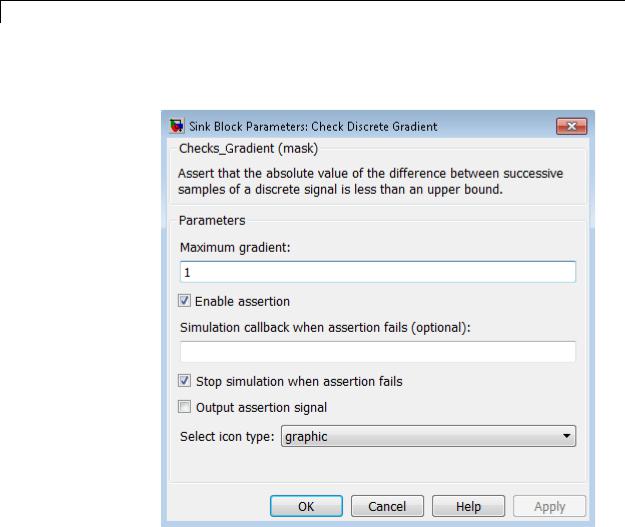
Check Discrete Gradient
Purpose |
Check that absolute value of difference between successive samples of |
|
discrete signal is less than upper bound |
Library |
Model Verification |
Description |
The Check Discrete Gradient block checks each signal element at its |
|
input to determine whether the absolute value of the difference between |
|
successive samples of the element is less than an upper bound. Use the |
|
block parameter dialog box to specify the value of the upper bound (1 |
|
by default). If the verification condition is true, the block does nothing. |
|
Otherwise, the block halts the simulation, by default, and displays an |
|
error message in the Simulation Diagnostics Viewer. |
|
The Model Verification block enabling setting under Debugging |
|
on the Data Validity diagnostics pane of the Configuration Parameters |
|
dialog box lets you enable or disable all model verification blocks, |
|
including Check Discrete Gradient blocks, in a model. |
|
The Check Discrete Gradient block and its companion blocks in |
|
the Model Verification library are intended to facilitate creation of |
|
self-validating models. For example, you can use model verification |
|
blocks to test that signals do not exceed specified limits during |
|
simulation. When you are satisfied that a model is correct, you can |
|
turn error checking off by disabling the verification blocks. You do not |
|
have to physically remove them from the model. If you need to modify |
|
a model, you can temporarily turn the verification blocks back on to |
|
ensure that your changes do not break the model. |
|
|
|
Note For information about how Simulink Coder generated code |
|
handles Model Verification blocks, see “Debug”. |
Data Type |
The Check Discrete Gradient block accepts single, double, int8, |
Support |
int16, and int32 input signals of any dimensions. This block also |
|
supports fixed-point data types. |
2-95
Check Discrete Gradient
Parameters and Dialog Box
For more information, see “Data Types Supported by Simulink” in the Simulink documentation.
Maximum gradient
Specify the upper bound on the gradient of the discrete input signal.
Enable assertion
Clearing this check box disables the Check Discrete Gradient block, that is, causes the model to behave as if the block did
2-96

Check Discrete Gradient
not exist. The Model Verification block enabling setting under Debugging on the Data Validity diagnostics pane of the Configuration Parameters dialog box allows you to enable or disable all model verification blocks in a model, including Check Discrete Gradient blocks, regardless of the setting of this option.
Simulation callback when assertion fails
Specify a MATLAB expression to evaluate when the assertion fails. Because the expression is evaluated in the MATLAB workspace, define all variables used in the expression in that workspace.
Stop simulation when assertion fails
Selecting this check box causes the Check Discrete Gradient block to halt the simulation when the block’s output is zero and display an error message in the Simulink Simulation Diagnostics Viewer. Otherwise, the block displays a warning message in the MATLAB Command Window and continues the simulation.
Output assertion signal
Selecting this check box causes the Check Discrete Gradient block to output a Boolean signal that is true (1) at each time step if the assertion succeeds and false (0) if the assertion fails. The data type of the output signal is Boolean if you have selected the
Implement logic signals as Boolean data check box on the
Optimization pane of the Configuration Parameters dialog box. Otherwise the data type of the output signal is double.
Select icon type
Specify the type of icon used to display this block in a block diagram: either graphic or text. The graphic option displays a graphical representation of the assertion condition on the icon. The text option displays a mathematical expression that represents the assertion condition. If the icon is too small to display the expression, the text icon displays an exclamation point. To see the expression, enlarge the block.
2-97

Check Discrete Gradient
Characteristics |
Direct Feedthrough |
No |
|
Sample Time |
Inherited from the driving block |
|
Scalar Expansion |
No |
|
Dimensionalized |
Yes |
|
Multidimensionalized |
Yes |
|
Zero-Crossing Detection |
No |
|
|
|
2-98

Check Dynamic Gap
Purpose |
Check that gap of possibly varying width occurs in range of signal’s |
|
amplitudes |
Library |
Model Verification |
Description |
|
The Check Dynamic Gap block checks that a gap of possibly varying width occurs in the range of a signal’s amplitudes. The test signal is the signal connected to the input labeled sig. The inputs labeled min and max specify the lower and upper bounds of the dynamic gap,
respectively. If the verification condition is true, the block does nothing. If not, the block halts the simulation, by default, and displays an error message.
The Check Dynamic Gap block and its companion blocks in the Model Verification library are intended to facilitate creation of self-validating models. For example, you can use model verification blocks to test that signals do not exceed specified limits during simulation. When you are satisfied that a model is correct, you can turn error checking off by disabling the verification blocks. You do not have to physically remove them from the model. If you need to modify a model, you can temporarily turn the verification blocks back on to ensure that your changes do not break the model.
Note For information about how Simulink Coder generated code handles Model Verification blocks, see “Debug”.
2-99

Check Dynamic Gap
Data Type
Support
Parameters and Dialog Box
The Check Dynamic Gap block accepts input signals of any dimensions and of any numeric data type that Simulink supports. All three input signals must have the same dimension and data type. If the inputs are nonscalar, the block checks each element of the input test signal to the corresponding elements of the reference signals.
For more information, see “Data Types Supported by Simulink” in the Simulink documentation.
Enable assertion
Clearing this check box disables the Check Dynamic Gap block, that is, causes the model to behave as if the block did not
2-100

Check Dynamic Gap
exist. The Model Verification block enabling setting under
Debugging on the Data Validity diagnostics pane of the Configuration Parameters dialog box allows you to enable or disable all model verification blocks in a model, including Check Dynamic Gap blocks, regardless of the setting of this option.
Simulation callback when assertion fails
Specify a MATLAB expression to evaluate when the assertion fails. Because the expression is evaluated in the MATLAB workspace, define all variables used in the expression in that workspace.
Stop simulation when assertion fails
Selecting this check box causes the Check Dynamic Gap block to halt the simulation when the block’s output is zero and display an error message in the Simulation Diagnostics Viewer. Otherwise, the block displays a warning message in the MATLAB Command Window and continues the simulation.
Output assertion signal
Selecting this check box causes the Check Dynamic Gap block to output a Boolean signal that is true (1) at each time step if the assertion succeeds and false (0) if the assertion fails. The data type of the output signal is Boolean if you have selected the
Implement logic signals as Boolean data check box on the
Optimization pane of the Configuration Parameters dialog box. Otherwise the data type of the output signal is double.
Select icon type
Specify the type of icon used to display this block in a block diagram: either graphic or text. The graphic option displays a graphical representation of the assertion condition on the icon. The text option displays a mathematical expression that represents the assertion condition. If the icon is too small to display the expression, the text icon displays an exclamation point. To see the expression, enlarge the block.
2-101

Check Dynamic Gap
Characteristics |
Direct Feedthrough |
No |
|
Sample Time |
Inherited from driving block |
|
Scalar Expansion |
No |
|
Dimensionalized |
Yes |
|
Multidimensionalized |
Yes |
|
Zero-Crossing Detection |
No |
|
|
|
2-102
Check Dynamic Lower Bound
Purpose |
Check that one signal is always less than another signal |
Library |
Model Verification |
Description |
|
Data Type
Support
The Check Dynamic Lower Bound block checks that the amplitude of a reference signal is less than the amplitude of a test signal at the current time step. The test signal is the signal connected to the input labeled sig. If the verification condition is true, the block does nothing. If not, the block halts the simulation, by default, and displays an error message.
The Check Dynamic Lower Bound block and its companion blocks in the Model Verification library are intended to facilitate creation of self-validating models. For example, you can use model verification blocks to test that signals do not exceed specified limits during simulation. When you are satisfied that a model is correct, you can turn error checking off by disabling the verification blocks. You do not have to physically remove them from the model. If you need to modify a model, you can temporarily turn the verification blocks back on to ensure that your changes do not break the model.
Note For information about how Simulink Coder generated code handles Model Verification blocks, see “Debug”.
The Check Dynamic Lower Bound block accepts input signals of any numeric data type that Simulink supports. The test and the reference signals must have the same dimensions and data type. If the inputs are
2-103

Check Dynamic Lower Bound
Parameters and Dialog Box
nonscalar, the block checks each element of the input test signal to the corresponding elements of the reference signal.
For more information, see “Data Types Supported by Simulink” in the Simulink documentation.
Enable assertion
Clearing this check box disables the Check Dynamic Lower Bound block, that is, causes the model to behave as if the block did not exist. The Model Verification block enabling setting under Debugging on the Data Validity diagnostics pane of the Configuration Parameters dialog box allows you to enable or disable all model verification blocks, including Check Dynamic
2-104

Check Dynamic Lower Bound
Lower Bound blocks, in a model regardless of the setting of this option.
Simulation callback when assertion fails
Specify a MATLAB expression to evaluate when the assertion fails. Because the expression is evaluated in the MATLAB workspace, define all variables used in the expression in that workspace.
Stop simulation when assertion fails
Selecting this check box causes the Check Dynamic Lower Bound block to halt the simulation when the block’s output is zero and display an error message in the Simulation Diagnostics Viewer. Otherwise, the block displays a warning message in the MATLAB Command Window and continues the simulation.
Output assertion signal
Selecting this check box causes the Check Dynamic Lower Bound block to output a Boolean signal that is true (1) at each time step if the assertion succeeds and false (0) if the assertion fails. The data type of the output signal is Boolean if you have selected the
Implement logic signals as Boolean data check box on the
Optimization pane of the Configuration Parameters dialog box. Otherwise the data type of the output signal is double.
Select icon type
Specify the type of icon used to display this block in a block diagram: either graphic or text. The graphic option displays a graphical representation of the assertion condition on the icon. The text option displays a mathematical expression that represents the assertion condition. If the icon is too small to display the expression, the text icon displays an exclamation point. To see the expression, enlarge the block.
Characteristics |
Direct Feedthrough |
No |
|
Sample Time |
Inherited from driving block |
|
|
|
2-105

Check Dynamic Lower Bound
Scalar Expansion |
No |
Dimensionalized |
Yes |
Multidimensionalized |
Yes |
Zero-Crossing Detection |
No |
|
|
2-106

Check Dynamic Range
Purpose |
Check that signal falls inside range of amplitudes that varies from time |
|
step to time step |
Library |
Model Verification |
Description |
|
The Check Dynamic Range block checks that a test signal falls inside a range of amplitudes at each time step. The width of the range can vary from time step to time step. The input labeled sig is the test signal. The inputs labeled min and max are the lower and upper bounds of the valid range at the current time step. If the verification condition is true, the block does nothing. If not, the block halts the simulation, by default, and displays an error message.
The Check Dynamic Range block and its companion blocks in the Model Verification library are intended to facilitate creation of self-validating models. For example, you can use model verification blocks to test that signals do not exceed specified limits during simulation. When you are satisfied that a model is correct, you can turn error checking off by disabling the verification blocks. You do not have to physically remove them from the model. If you need to modify a model, you can temporarily turn the verification blocks back on to ensure that your changes do not break the model.
Note For information about how Simulink Coder generated code handles Model Verification blocks, see “Debug”.
2-107

Check Dynamic Range
Data Type
Support
Parameters and Dialog Box
The Check Dynamic Range block accepts input signals of any dimensions and of any numeric data type that Simulink supports. All three input signals must have the same dimension and data type. If the inputs are nonscalar, the block checks each element of the input test signal to the corresponding elements of the reference signals.
For more information, see “Data Types Supported by Simulink” in the Simulink documentation.
Enable assertion
Clearing this check box disables the Check Dynamic Range block, that is, causes the model to behave as if the block did not exist. The Model Verification block enabling setting
2-108

Check Dynamic Range
under Debugging on the Data Validity diagnostics pane of the Configuration Parameters dialog box allows you to enable or disable all model verification blocks in a model, including Check Dynamic Range blocks, regardless of the setting of this option.
Simulation callback when assertion fails
Specify a MATLAB expression to evaluate when the assertion fails. Because the expression is evaluated in the MATLAB workspace, define all variables used in the expression in that workspace.
Stop simulation when assertion fails
Selecting this check box causes the Check Dynamic Range block to halt the simulation when the block’s output is zero and display an error message in the Simulation Diagnostics Viewer. Otherwise, the block displays a warning message in the MATLAB Command Window and continues the simulation.
Output assertion signal
Selecting this check box causes the Check Dynamic Range block to output a Boolean signal that is true (1) at each time step if the assertion succeeds and false (0) if the assertion fails. The data type of the output signal is Boolean if you selected the
Implement logic signals as Boolean data check box on the
Optimization pane of the Configuration Parameters dialog box. Otherwise the data type of the output signal is double.
Select icon type
Specify the type of icon used to display this block in a block diagram: either graphic or text. The graphic option displays a graphical representation of the assertion condition on the icon. The text option displays a mathematical expression that represents the assertion condition. If the icon is too small to display the expression, the text icon displays an exclamation point. To see the expression, enlarge the block.
2-109

Check Dynamic Range
Characteristics |
Direct Feedthrough |
No |
|
Sample Time |
Inherited from driving block |
|
Scalar Expansion |
No |
|
Dimensionalized |
Yes |
|
Multidimensionalized |
Yes |
|
Zero-Crossing Detection |
No |
|
|
|
2-110

Check Dynamic Upper Bound
Purpose |
Check that one signal is always greater than another signal |
Library |
Model Verification |
Description |
|
Data Type
Support
The Check Dynamic Upper Bound block checks that the amplitude of a reference signal is greater than the amplitude of a test signal at the current time step. The test signal is the signal connected to the input labeled sig. If the verification condition is true, the block does nothing. If not, the block halts the simulation, by default, and displays an error message.
The Check Dynamic Upper Bound block and its companion blocks in the Model Verification library are intended to facilitate creation of self-validating models. For example, you can use model verification blocks to test that signals do not exceed specified limits during simulation. When you are satisfied that a model is correct, you can turn error-checking off by disabling the verification blocks. You do not have to physically remove them from the model. If you need to modify a model, you can temporarily turn the verification blocks back on to ensure that your changes do not break the model.
Note For information about how Simulink Coder generated code handles Model Verification blocks, see “Debug”.
The Check Dynamic Upper Bound block accepts input signals of any dimensions and of any numeric data type that Simulink supports. The test and the reference signals must have the same dimensions and data
2-111

Check Dynamic Upper Bound
Parameters and Dialog Box
type. If the inputs are nonscalar, the block compares each element of the input test signal to the corresponding elements of the reference signal.
For more information, see “Data Types Supported by Simulink” in the Simulink documentation.
Enable assertion
Clearing this check box disables the Check Dynamic Upper Bound block, that is, causes the model to behave as if the block did not exist. The Model Verification block enabling setting under Debugging on the Data Validity diagnostics pane of the Configuration Parameters dialog box allows you to enable or disable all model verification blocks, including Check Dynamic
2-112
Check Dynamic Upper Bound
Upper Bound blocks, in a model regardless of the setting of this option.
Simulation callback when assertion fails
Specify a MATLAB expression to evaluate when the assertion fails. Because the expression is evaluated in the MATLAB workspace, define all variables used in the expression in that workspace.
Stop simulation when assertion fails
Selecting this check box causes the Check Dynamic Upper Bound block to halt the simulation when the block’s output is zero and display an error message in the Simulation Diagnostics Viewer. Otherwise, the block displays a warning message in the MATLAB Command Window and continues the simulation.
Output assertion signal
Selecting this check box causes the Check Dynamic Upper Bound block to output a Boolean signal that is true (1) at each time step if the assertion succeeds and false (0) if the assertion fails. The data type of the output signal is Boolean if you have selected the
Implement logic signals as Boolean data check box on the
Optimization pane of the Configuration Parameters dialog box. Otherwise the data type of the output signal is double.
Select icon type
Specify the type of icon used to display this block in a block diagram: either graphic or text. The graphic option displays a graphical representation of the assertion condition on the icon. The text option displays a mathematical expression that represents the assertion condition. If the icon is too small to display the expression, the text icon displays an exclamation point. To see the expression, enlarge the block.
Characteristics |
Direct Feedthrough |
No |
|
Sample Time |
Inherited from driving block |
|
|
|
2-113

Check Dynamic Upper Bound
Scalar Expansion |
No |
Dimensionalized |
Yes |
Multidimensionalized |
Yes |
Zero-Crossing Detection |
No |
|
|
2-114

Check Input Resolution
Purpose |
Check that input signal has specified resolution |
Library |
Model Verification |
Description |
The Check Input Resolution block checks whether the input signal has |
|
a specified scalar or vector resolution (see Resolution). If the resolution |
|
is a scalar, the input signal must be a multiple of the resolution within |
|
a 10e-3 tolerance. If the resolution is a vector, the input signal must |
|
equal an element of the resolution vector. If the verification condition is |
|
true, the block does nothing. If not, the block halts the simulation, by |
|
default, and displays an error message. |
|
The Check Input Resolution block and its companion blocks in the Model |
|
Verification library are intended to facilitate creation of self-validating |
|
models. For example, you can use model verification blocks to test |
|
that signals do not exceed specified limits during simulation. When |
|
you are satisfied that a model is correct, you can turn error checking |
|
off by disabling the verification blocks. You do not have to physically |
|
remove them from the model. If you need to modify a model, you can |
|
temporarily turn the verification blocks back on to ensure that your |
|
changes do not break the model. |
|
|
|
Note For information about how Simulink Coder generated code |
|
handles Model Verification blocks, see “Debug”. |
Data Type |
The Check Input Resolution block accepts input signals of data type |
Support |
double and of any dimension. If the input signal is nonscalar, the block |
|
checks the resolution of each element of the input test signal. |
|
For more information, see “Data Types Supported by Simulink” in the |
|
Simulink documentation. |
2-115

Check Input Resolution
Parameters and Dialog Box
Resolution
Specify the resolution that the input signal must have.
Enable assertion
Clearing this check box disables the Check Input Resolution block, that is, causes the model to behave as if the block did not exist. The Model Verification block enabling setting under Debugging on the Data Validity diagnostics pane of the Configuration Parameters dialog box allows you to enable or
2-116

Check Input Resolution
disable all model verification blocks in a model, including Check Input Resolution blocks, regardless of the setting of this option.
Simulation callback when assertion fails
Specify a MATLAB expression to evaluate when the assertion fails. Because the expression is evaluated in the MATLAB workspace, define all variables used in the expression in that workspace.
Stop simulation when assertion fails
Selecting this check box causes the Check Input Resolution block to halt the simulation when the block’s output is zero and display an error message in the Simulation Diagnostics Viewer. Otherwise, the block displays a warning message in the MATLAB Command Window and continues the simulation.
Output assertion signal
Selecting this check box causes the Check Input Resolution block to output a Boolean signal that is true (1) at each time step if the assertion succeeds and false (0) if the assertion fails. The data type of the output signal is Boolean if you have selected the
Implement logic signals as Boolean data check box on the
Optimization pane of the Configuration Parameters dialog box. Otherwise the data type of the output signal is double.
Characteristics |
Direct Feedthrough |
No |
|
Sample Time |
Inherited from driving block |
|
Scalar Expansion |
No |
|
Dimensionalized |
Yes |
|
Multidimensionalized |
Yes |
|
Zero-Crossing Detection |
No |
|
|
|
2-117

Check Static Gap
Purpose |
Check that gap exists in signal’s range of amplitudes |
Library |
Model Verification |
Description |
The Check Static Gap block checks that each element of the input signal |
|
is less than (or optionally equal to) a static lower bound or greater than |
|
(or optionally equal to) a static upper bound at the current time step. |
|
If the verification condition is true, the block does nothing. If not, the |
|
block halts the simulation, by default, and displays an error message. |
|
The Check Static Gap block and its companion blocks in the Model |
|
Verification library are intended to facilitate creation of self-validating |
|
models. For example, you can use model verification blocks to test |
|
that signals do not exceed specified limits during simulation. When |
|
you are satisfied that a model is correct, you can turn error checking |
|
off by disabling the verification blocks. You do not have to physically |
|
remove them from the model. If you need to modify a model, you can |
|
temporarily turn the verification blocks back on to ensure that your |
|
changes do not break the model. |
|
|
|
Note For information about how Simulink Coder generated code |
|
handles Model Verification blocks, see “Debug”. |
Data Type |
The Check Static Gap block accepts input signals of any dimensions and |
Support |
of any numeric data type that Simulink supports. |
|
For more information, see “Data Types Supported by Simulink” in the |
|
Simulink documentation. |
2-118
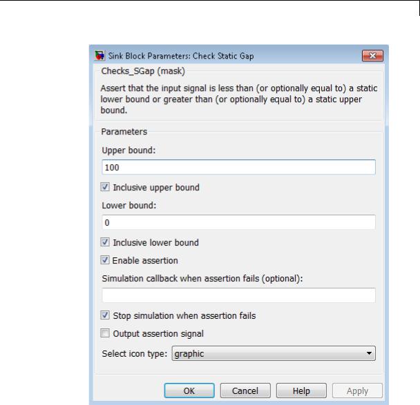
Check Static Gap
Parameters and Dialog Box
Upper bound
Specify the upper bound of the gap in the input signal’s range of amplitudes.
2-119

Check Static Gap
Inclusive upper bound
Selecting this check box specifies that the gap includes the upper bound.
Lower bound
Specify the lower bound of the gap in the input signal’s range of amplitudes.
Inclusive lower bound
Selecting this check box specifies that the gap includes the lower bound.
Enable assertion
Clearing this check box disables the Check Static Gap block, that is, causes the model to behave as if the block did not exist. The
Model Verification block enabling setting under Debugging on the Data Validity diagnostics pane of the Configuration Parameters dialog box allows you to enable or disable all model verification blocks in a model, including Check Static Gap blocks, regardless of the setting of this option.
Simulation callback when assertion fails
Specify a MATLAB expression to evaluate when the assertion fails. Because the expression is evaluated in the MATLAB workspace, define all variables used in the expression in that workspace.
Stop simulation when assertion fails
Selecting this check box causes the Check Static Gap block to halt the simulation when the block’s output is zero and display an error message in the Simulation Diagnostics Viewer. Otherwise, the block displays a warning message in the MATLAB Command Window and continues the simulation.
Output assertion signal
Selecting this check box causes the Check Static Gap block to output a Boolean signal that is true (1) at each time step if the assertion succeeds and false (0) if the assertion fails. The data type of the output signal is Boolean if you have selected the
Implement logic signals as Boolean data check box on the
2-120

Check Static Gap
Optimization pane of the Configuration Parameters dialog box. Otherwise the data type of the output signal is double.
Select icon type
Specify the type of icon used to display this block in a block diagram: either graphic or text. The graphic option displays a graphical representation of the assertion condition on the icon. The text option displays a mathematical expression that represents the assertion condition. If the icon is too small to display the expression, the text icon displays an exclamation point. To see the expression, enlarge the block.
Characteristics |
Direct Feedthrough |
No |
|
Sample Time |
Inherited from the driving block |
|
Scalar Expansion |
No |
|
Dimensionalized |
Yes |
|
Multidimensionalized |
Yes |
|
Zero-Crossing Detection |
No |
|
|
|
2-121

Check Static Lower Bound
Purpose |
Check that signal is greater than (or optionally equal to) static lower |
|
bound |
Library |
Model Verification |
Description |
The Check Static Lower Bound block checks that each element of the |
|
input signal is greater than (or optionally equal to) a specified lower |
|
bound at the current time step. Use the block parameter dialog box to |
|
specify the value of the lower bound and whether the lower bound is |
|
inclusive. If the verification condition is true, the block does nothing. If |
|
not, the block halts the simulation, by default, and displays an error |
|
message. |
|
The Check Static Lower Bound block and its companion blocks in |
|
the Model Verification library are intended to facilitate creation of |
|
self-validating models. For example, you can use model verification |
|
blocks to test that signals do not exceed specified limits during |
|
simulation. When you are satisfied that a model is correct, you can |
|
turn error checking off by disabling the verification blocks. You do not |
|
have to physically remove them from the model. If you need to modify |
|
a model, you can temporarily turn the verification blocks back on to |
|
ensure that your changes do not break the model. |
|
|
|
Note For information about how Simulink Coder generated code |
|
handles Model Verification blocks, see “Debug”. |
Data Type |
The Check Static Lower Bound block accepts input signals of any |
Support |
dimensions and of any numeric data type that Simulink supports. |
|
For more information, see “Data Types Supported by Simulink” in the |
|
Simulink documentation. |
2-122
Check Static Lower Bound
Parameters and Dialog Box
Lower bound
Specify the lower bound on the range of amplitudes that the input signal can have.
Inclusive boundary
Selecting this check box makes the range of valid input amplitudes include the lower bound.
2-123

Check Static Lower Bound
Enable assertion
Clearing this check box disables the Check Static Lower Bound block, that is, causes the model to behave as if the block did not exist. The Model Verification block enabling setting under Debugging on the Data Validity diagnostics pane of the Configuration Parameters dialog box allows you to enable or disable all model verification blocks in a model, including Check
Static Lower Bound blocks, regardless of the setting of this option.
Simulation callback when assertion fails
Specify a MATLAB expression to evaluate when the assertion fails. Because the expression is evaluated in the MATLAB workspace, define all variables used in the expression in that workspace.
Stop simulation when assertion fails
Selecting this check box causes the Check Static Lower Bound block to halt the simulation when the block’s output is zero and display an error message in the Simulation Diagnostics Viewer.
Otherwise, the block displays a warning message in the MATLAB Command Window and continues the simulation.
Output assertion signal
Selecting this check box causes the Check Static Lower Bound block to output a Boolean signal that is true (1) at each time step if the assertion succeeds and false (0) if the assertion fails. The data type of the output signal is Boolean if you have selected the
Implement logic signals as Boolean data check box on the
Optimization pane of the Configuration Parameters dialog box. Otherwise the data type of the output signal is double.
Select icon type
Specify the type of icon used to display this block in a block diagram: either graphic or text. The graphic option displays a graphical representation of the assertion condition on the icon. The text option displays a mathematical expression that represents the assertion condition. If the icon is too small to display the expression, the text icon displays an exclamation point. To see the expression, enlarge the block.
2-124

Check Static Lower Bound
Characteristics |
Direct Feedthrough |
No |
|
Sample Time |
Inherited from driving block |
|
Scalar Expansion |
No |
|
Dimensionalized |
Yes |
|
Multidimensionalized |
Yes |
|
Zero-Crossing Detection |
No |
|
|
|
2-125

Check Static Range
Purpose |
Check that signal falls inside fixed range of amplitudes |
Library |
Model Verification |
Description |
The Check Static Range block checks that each element of the input |
|
signal falls inside the same range of amplitudes at each time step. Use |
|
the block parameter dialog box to specify the upper and lower bounds of |
|
the valid amplitude range and whether the range includes the bounds. |
|
If the verification condition is true, the block does nothing. If not, the |
|
block halts the simulation, by default, and displays an error message. |
|
The Check Static Range block and its companion blocks in the Model |
|
Verification library are intended to facilitate creation of self-validating |
|
models. For example, you can use model verification blocks to test |
|
that signals do not exceed specified limits during simulation. When |
|
you are satisfied that a model is correct, you can turn error checking |
|
off by disabling the verification blocks. You do not have to physically |
|
remove them from the model. If you need to modify a model, you can |
|
temporarily turn the verification blocks back on to ensure that your |
|
changes do not break the model. |
|
|
|
Note For information about how Simulink Coder generated code |
|
handles Model Verification blocks, see “Debug”. |
Data Type |
The Check Static Range block accepts input signals of any dimensions |
Support |
and of any numeric data type that Simulink supports. |
|
For more information, see “Data Types Supported by Simulink” in the |
|
Simulink documentation. |
2-126

Check Static Range
Parameters and Dialog Box
Upper bound
Specify the upper bound of the range of valid input signal amplitudes.
2-127

Check Static Range
Inclusive upper bound
Selecting this check box specifies that the valid signal range includes the upper bound.
Lower bound
Specify the lower bound of the range of valid input signal amplitudes.
Inclusive lower bound
Selecting this check box specifies that the valid signal range includes the lower bound.
Enable assertion
Clearing this check box disables the Check Static Range block, that is, causes the model to behave as if the block did not exist. The Model Verification block enabling setting under
Debugging on the Data Validity diagnostics pane of the Configuration Parameters dialog box allows you to enable or disable all model verification blocks in a model, including Check Static Range blocks, regardless of the setting of this option.
Simulation callback when assertion fails
Specify a MATLAB expression to evaluate when the assertion fails. Because the expression is evaluated in the MATLAB workspace, define all variables used in the expression in that workspace.
Stop simulation when assertion fails
Selecting this check box causes the Check Static Range block to halt the simulation when the block’s output is zero and display an error message in the Simulation Diagnostics Viewer. Otherwise, the block displays a warning message in the MATLAB Command Window and continues the simulation.
Output assertion signal
Selecting this check box causes the Check Static Range block to output a Boolean signal that is true (1) at each time step if the assertion succeeds and false (0) if the assertion fails. The
data type of the output signal is Boolean if you have selected the
Implement logic signals as Boolean data check box on the
2-128
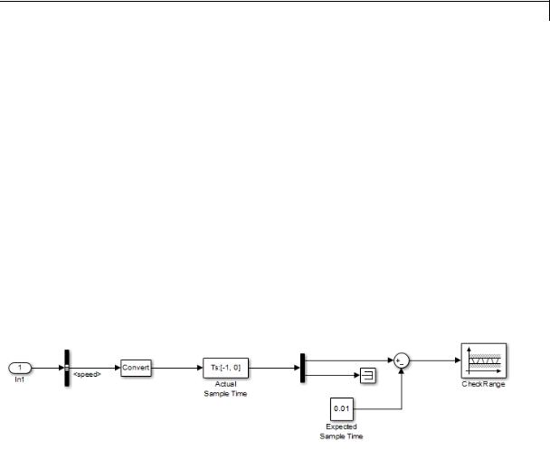
Check Static Range
Optimization pane of the Configuration Parameters dialog box. Otherwise the data type of the output signal is double.
Select icon type
Specify the type of icon used to display this block in a block diagram: either graphic or text. The graphic option displays a graphical representation of the assertion condition on the icon. The text option displays a mathematical expression that represents the assertion condition. If the icon is too small to display the expression, the text icon displays an exclamation point. To see the expression, enlarge the block.
Examples The sldemo_fuelsys model shows how you can use the Check Static Range block to verify that the sample time is consistent throughout the model.
The Check Static Range block appears in the
sldemo_fuelsys/fuel_rate_control/validate_sample_time subsystem.
Characteristics |
Direct Feedthrough |
No |
|
Sample Time |
Inherited from the driving block |
|
Scalar Expansion |
No |
|
Dimensionalized |
Yes |
|
|
|
2-129

Check Static Range
Multidimensionalized |
Yes |
Zero-Crossing Detection |
No |
|
|
2-130

Check Static Upper Bound
Purpose |
Check that signal is less than (or optionally equal to) static upper bound |
Library |
Model Verification |
Description |
The Check Static Upper Bound block checks that each element of the |
|
input signal is less than (or optionally equal to) a specified upper bound |
|
at the current time step. Use the block parameter dialog box to specify |
|
the value of the upper bound and whether the bound is inclusive. If the |
|
verification condition is true, the block does nothing. If not, the block |
|
halts the simulation, by default, and displays an error message. |
|
The Check Static Upper Bound block and its companion blocks in |
|
the Model Verification library are intended to facilitate creation of |
|
self-validating models. For example, you can use model verification |
|
blocks to test that signals do not exceed specified limits during |
|
simulation. When you are satisfied that a model is correct, you can |
|
turn error checking off by disabling the verification blocks. You do not |
|
have to physically remove them from the model. If you need to modify |
|
a model, you can temporarily turn the verification blocks back on to |
|
ensure that your changes do not break the model. |
|
|
|
Note For information about how Simulink Coder generated code |
|
handles Model Verification blocks, see “Debug”. |
Data Type |
The Check Static Upper Bound block accepts input signals of any |
Support |
dimensions and of any numeric data type that Simulink supports. |
|
For more information, see “Data Types Supported by Simulink” in the |
|
Simulink documentation. |
2-131

Check Static Upper Bound
Parameters and Dialog Box
Upper bound
Specify the upper bound on the range of amplitudes that the input signal can have.
Inclusive boundary
Selecting this check box makes the range of valid input amplitudes include the upper bound.
2-132
Check Static Upper Bound
Enable assertion
Clearing this check box disables the Check Static Upper Bound block, that is, causes the model to behave as if the block did not exist. The Model Verification block enabling setting under Debugging on the Data Validity diagnostics pane of the Configuration Parameters dialog box allows you to enable or disable all model verification blocks in a model, including Check
Static Upper Bound blocks, regardless of the setting of this option.
Simulation callback when assertion fails
Specify a MATLAB expression to evaluate when the assertion fails. Because the expression is evaluated in the MATLAB workspace, define all variables used in the expression in that workspace.
Stop simulation when assertion fails
Selecting this check box causes the Check Static Upper Bound block to halt the simulation when the block’s output is zero and display an error message in the Simulation Diagnostics Viewer.
Otherwise, the block displays a warning message in the MATLAB Command Window and continues the simulation.
Output assertion signal
Selecting this check box causes the Check Static Upper Bound block to output a Boolean signal that is true (1) at each time step if the assertion succeeds and false (0) if the assertion fails. The data type of the output signal is Boolean if you have selected the
Implement logic signals as Boolean data check box on the
Optimization pane of the Configuration Parameters dialog box. Otherwise the data type of the output signal is double.
Select icon type
Specify the type of icon used to display this block in a block diagram: either graphic or text. The graphic option displays a graphical representation of the assertion condition on the icon. The text option displays a mathematical expression that represents the assertion condition. If the icon is too small to display the expression, the text icon displays an exclamation point. To see the expression, enlarge the block.
2-133

Check Static Upper Bound
Characteristics |
Direct Feedthrough |
No |
|
Sample Time |
Inherited from driving block |
|
Scalar Expansion |
No |
|
Dimensionalized |
Yes |
|
Multidimensionalized |
Yes |
|
Zero-Crossing Detection |
No |
|
|
|
2-134

Chirp Signal
Purpose |
Generate sine wave with increasing frequency |
Library Sources
Description The Chirp Signal block generates a sine wave whose frequency increases at a linear rate with time. You can use this block for spectral analysis of nonlinear systems. The block generates a scalar or vector output.
The parameters, Initial frequency, Target time, and Frequency at target time, determine the block’s output. You can specify any or all of these variables as scalars or arrays. All the parameters specified as arrays must have the same dimensions. The block expands scalar parameters to have the same dimensions as the array parameters. The block output has the same dimensions as the parameters unless you select the Interpret vector parameters as 1-D check box. If you
select this check box and the parameters are row or column vectors, the block outputs a vector (1-D array) signal.
The following limitations apply to the Chirp Signal block:
•The start time of the simulation must be 0. To confirm this value, go to the Solver pane in the Configuration Parameters dialog box and view the Start time field.
•Suppose that you use a Chirp Signal block in an enabled subsystem. Whenever the subsystem is enabled, the block output matches what would appear if the subsystem were enabled throughout the simulation.
Data Type The Chirp Signal block outputs a real-valued signal of type double.
Support For more information, see “Data Types Supported by Simulink” in the Simulink documentation.
2-135

Chirp Signal
Parameters and Dialog Box
Initial frequency
The initial frequency of the signal, specified as a scalar or matrix value. The default is 0.1 Hz.
Target time
The time at which the frequency reaches the Frequency at target time parameter value, a scalar or matrix value. The frequency continues to change at the same rate after this time. The default is 100 seconds.
2-136

Chirp Signal
Frequency at target time
The frequency of the signal at the target time, a scalar or matrix value. The default is 1 Hz.
Interpret vector parameters as 1-D
If selected, column or row matrix values for the Initial frequency, Target time, and Frequency at target time parameters result in a vector output whose elements are the elements of the row or column. For more information, see “Determining the Output Dimensions of Source Blocks” in the Simulink documentation.
Characteristics |
Sample Time |
Continuous |
|
Scalar Expansion |
Yes, of parameters |
|
Dimensionalized |
Yes |
|
Zero-Crossing Detection |
No |
|
|
|
2-137

Clock
Purpose |
Display and provide simulation time |
Library Sources
Description The Clock block outputs the current simulation time at each simulation step. This block is useful for other blocks that need the simulation time.
When you need the current time within a discrete system, use the Digital Clock block.
Data Type
Support
Parameters and Dialog Box
The Clock block outputs a real-valued signal of type double.
For more information, see “Data Types Supported by Simulink” in the Simulink documentation.
Display time
Select this check box to display the current simulation time inside the Clock block icon.
2-138

Clock
Decimation
Specify a positive integer for the interval at which Simulink updates the Clock icon when you select Display time.
Suppose that the decimation is 1000. For a fixed integration step of 1 millisecond, the Clock icon updates at 1 second, 2 seconds, and so on.
Examples The following Simulink examples show how to use the Clock block:
•sldemo_tonegen_fixpt
•penddemo
Characteristics
See Also
Sample Time |
Continuous |
Scalar Expansion |
N/A |
Dimensionalized |
No |
Zero-Crossing Detection |
No |
|
|
Digital Clock
2-139

Combinatorial Logic
Purpose
Library
Description
Implement truth table
Logic and Bit Operations
The Combinatorial Logic block implements a standard truth table for modeling programmable logic arrays (PLAs), logic circuits, decision tables, and other Boolean expressions. You can use this block in conjunction with Memory blocks to implement finite-state machines or flip-flops.
You specify a matrix that defines all possible block outputs as the Truth table parameter. Each row of the matrix contains the output for a different combination of input elements. You must specify outputs for every combination of inputs. The number of columns is the number of block outputs.
The relationship between the number of inputs and the number of rows is:
number of rows = 2 ^ (number of inputs)
Simulink returns a row of the matrix by computing the row’s index from the input vector elements. Simulink computes the index by building a binary number where input vector elements having zero values are 0 and elements having nonzero values are 1, then adding 1 to the result. For an input vector, u, of m elements:
row index = 1 + u(m)*20 + u(m-1)*21 + ... + u(1)*2m-1
Two-Input AND Logic
This example builds a two-input AND function, which returns 1 when both input elements are 1, and 0 otherwise. To implement this function, specify the Truth table parameter value as [0; 0; 0; 1]. The portion of the model that provides the inputs to and the output from the Combinatorial Logic block might look like this:
2-140
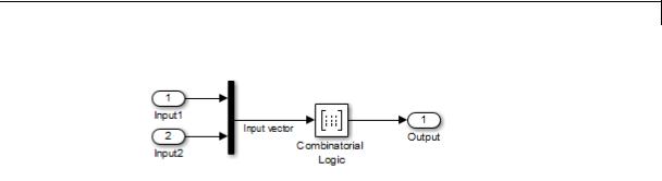
Combinatorial Logic
The following table indicates the combination of inputs that generate each output. The input signal labeled “Input 1” corresponds to the column in the table labeled Input 1. Similarly, the input signal “Input 2” corresponds to the column with the same name. The combination of these values determines the row of the Output column of the table that is passed as block output.
For example, if the input vector is [1 0], the input references the third row:
(2^1*1 + 1)
The output value is 0.
|
|
Row |
|
Input 1 |
Input 2 |
Output |
|
|
1 |
|
0 |
|
0 |
0 |
|
|
2 |
|
0 |
|
1 |
0 |
|
|
3 |
|
1 |
|
0 |
0 |
|
|
4 |
|
1 |
|
1 |
1 |
|
|
|
|
|
|
|
|
|
Circuit Logic
This sample circuit has three inputs: the two bits (a and b) to be summed and a carry-in bit (c). It has two outputs: the carry-out bit (c’) and the sum bit (s).
2-141

Combinatorial Logic
The truth table and corresponding outputs for each combination of input values for this circuit appear in the following table.
|
|
Inputs |
|
Outputs |
||
a |
b |
|
c |
c’ |
|
s |
0 |
0 |
|
0 |
0 |
|
0 |
0 |
0 |
|
1 |
0 |
|
1 |
0 |
1 |
|
0 |
0 |
|
1 |
0 |
1 |
|
1 |
1 |
|
0 |
1 |
0 |
|
0 |
0 |
|
1 |
1 |
0 |
|
1 |
1 |
|
0 |
1 |
1 |
|
0 |
1 |
|
0 |
1 |
1 |
|
1 |
1 |
|
1 |
|
|
|
|
|
|
|
To implement this adder with the Combinatorial Logic block, you enter the 8-by-2 matrix formed by columns c’ and s as the Truth table parameter.
You can also implement sequential circuits (that is, circuits with states) with the Combinatorial Logic block by including an additional input for the state of the block and feeding the output of the block back into this state input.
2-142
Combinatorial Logic
Data Type
Support
The type of signals accepted by a Combinatorial Logic block depends on whether you selected the Boolean logic signals option (see “Implement logic signals as Boolean data (vs. double)”). If this option is enabled, the block accepts real signals of type Boolean or double. The Truth table parameter can have Boolean values (0 or 1) of any data type, including fixed-point data types. If the table contains non-Boolean values, the data type of the table must be double.
The type of the output is the same as that of the input except that the block outputs double if the input is Boolean and the truth table contains non-Boolean values.
If Boolean compatibility mode is disabled, the Combinatorial Logic block accepts only signals of type Boolean. The block outputs double if the truth table contains non-Boolean values of type double. Otherwise, the output is Boolean.
For more information, see “Data Types Supported by Simulink” in the Simulink documentation.
2-143

Combinatorial Logic
Parameters and Dialog Box
Truth table
Specify the matrix of outputs. Each column corresponds to an element of the output vector and each row corresponds to a row of the truth table.
Sample time (-1 for inherited)
Specify the time interval between samples. To inherit the sample time, set this parameter to -1. See “Specify Sample Time” in the Simulink documentation.
2-144

Combinatorial Logic
Examples Usage with the Memory Block to Implement a Finite-State Machine
The sldemo_clutch model shows how you can use the Combinatorial Logic block with the Memory block to implement a finite-state machine.
The finite-state machine appears in the Friction Mode Logic/Lockup FSM subsystem.
2-145
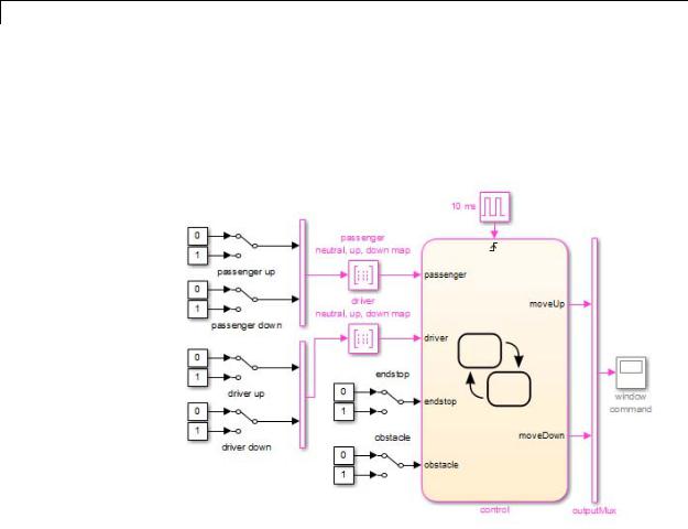
Combinatorial Logic
Usage with a Stateflow® Chart to Implement a Finite-State Machine
The powerwindow model shows how you can use two Combinatorial Logic blocks as inputs to a Stateflow chart to implement a finite-state machine.
Characteristics |
Direct Feedthrough |
Yes |
|
Sample Time |
Inherited from the driving block |
|
Scalar Expansion |
No |
|
Dimensionalized |
Yes, the output width is the number of |
|
|
columns of the Truth table parameter |
|
Zero-Crossing Detection |
No |
|
|
|
2-146

Compare To Constant
Purpose |
Determine how signal compares to specified constant |
Library |
Logic and Bit Operations |
Description |
The Compare To Constant block compares an input signal to a constant. |
|
Specify the constant in the Constant value parameter. Specify how the |
|
input is compared to the constant value with the Operator parameter. |
|
The Operator parameter can have the following values: |
|
• == — Determine whether the input is equal to the specified constant. |
|
• ~= — Determine whether the input is not equal to the specified |
|
constant. |
|
• < — Determine whether the input is less than the specified constant. |
|
• <= — Determine whether the input is less than or equal to the |
|
specified constant. |
|
• > — Determine whether the input is greater than the specified |
|
constant. |
|
• >= — Determine whether the input is greater than or equal to the |
|
specified constant. |
|
The output is 0 if the comparison is false, and 1 if it is true. |
Data Type |
The Compare To Constant block accepts inputs of any data type that |
Support |
Simulink supports, including fixed-point and enumerated data types. |
|
The block first converts its Constant value parameter to the input |
|
data type, and then performs the specified operation. The block output |
|
is uint8 or boolean as specified by the Output data type parameter. |
|
For more information, see “Data Types Supported by Simulink” in the |
|
Simulink documentation. |
2-147

Compare To Constant
Parameters and Dialog Box
Operator
Specify how the input is compared to the constant value, as discussed in Description.
Constant value
Specify the constant value to which the input is compared.
Output data type
Specify the data type of the output, boolean or uint8.
Enable zero-crossing detection
Select to enable zero-crossing detection. For more information, see “Zero-Crossing Detection” in the Simulink documentation.
2-148

Compare To Constant
Characteristics
See Also
Direct Feedthrough |
Yes |
Scalar Expansion |
Yes |
Multidimensionalized |
Yes |
Zero-Crossing Detection |
Yes, if enabled. |
|
|
Compare To Zero
2-149

Compare To Zero
Purpose |
Determine how signal compares to zero |
Library |
Logic and Bit Operations |
Description |
The Compare To Zero block compares an input signal to zero. Specify |
|
how the input is compared to zero with the Operator parameter. The |
|
Operator parameter can have the following values: |
|
• == — Determine whether the input is equal to zero. |
|
• ~= — Determine whether the input is not equal to zero. |
|
• < — Determine whether the input is less than zero. |
|
• <= — Determine whether the input is less than or equal to zero. |
|
• > — Determine whether the input is greater than zero. |
|
• >= — Determine whether the input is greater than or equal to zero. |
|
The output is 0 if the comparison is false, and 1 if it is true. |
Data Type The Compare To Zero block accepts inputs of the following data types:
Support
•Floating point
•Built-in integer
•Fixed point
•Boolean
The block output is uint8 or boolean, depending on your selection for the Output data type parameter. For more information, see “Data Types Supported by Simulink” in the Simulink documentation.
2-150

Compare To Zero
Parameters and Dialog Box
Tip If the input data type cannot represent zero, parameter overflow occurs. To detect this overflow, go to the Diagnostics > Data Validity pane of the Configuration Parameters dialog box and set Parameters > Detect overflow to warning or error.
In this case, the block compares the input signal to the ground value of the input data type. For example, if you have an input signal of type fixdt(0,8,2^0,10), the input data type can represent unsigned 8-bit integers from 10 to 265 due to a bias of 10. The ground value is 10, instead of 0.
Operator
Specify how the input is compared to zero, as discussed in Description.
Output data type
Specify the data type of the output, boolean or uint8.
2-151

Compare To Zero
Enable zero-crossing detection
Select to enable zero-crossing detection. For more information, see “Zero-Crossing Detection” in the Simulink documentation.
Characteristics |
|
Direct Feedthrough |
Yes |
|
|
Scalar Expansion |
Yes |
|
|
Multidimensionalized |
Yes |
|
|
Zero-Crossing Detection |
Yes, if enabled. |
See Also |
|
Compare To Constant |
|
2-152
Complex to Magnitude-Angle
Purpose |
Compute magnitude and/or phase angle of complex signal |
Library |
Math Operations |
Description |
The Complex to Magnitude-Angle block accepts a complex-valued signal |
|
of type double or single. It outputs the magnitude and/or phase angle |
|
of the input signal, depending on the setting of the Output parameter. |
|
The outputs are real values of the same data type as the block input. |
|
The input can be an array of complex signals, in which case the output |
|
signals are also arrays. The magnitude signal array contains the |
|
magnitudes of the corresponding complex input elements. The angle |
|
output similarly contains the angles of the input elements. |
Data Type
Support
See the preceding description.
2-153

Complex to Magnitude-Angle
Parameters and Dialog Box
Output
Determines the output of this block. Choose from the following values: Magnitude and angle (outputs the input signal’s magnitude and phase angle in radians), Magnitude (outputs the input’s magnitude), Angle (outputs the input’s phase angle in radians).
Sample time (-1 for inherited)
Specify the time interval between samples. To inherit the sample time, set this parameter to -1. For more information, see “Specify Sample Time” in the Simulink documentation.
Characteristics |
Direct Feedthrough |
Yes |
|
Sample Time |
Specified by the Sample time parameter |
|
Scalar Expansion |
No |
|
Dimensionalized |
Yes |
|
|
|
2-154

Complex to Magnitude-Angle
Multidimensionalized |
Yes |
Zero-Crossing Detection |
No |
|
|
2-155

Complex to Real-Imag
Purpose |
Output real and imaginary parts of complex input signal |
Library |
Math Operations |
Description |
The Complex to Real-Imag block accepts a complex-valued signal of any |
|
data type that Simulink supports, including fixed-point data types. It |
|
outputs the real and/or imaginary part of the input signal, depending on |
|
the setting of the Output parameter. The real outputs are of the same |
|
data type as the complex input. The input can be an array (vector or |
|
matrix) of complex signals, in which case the output signals are arrays |
|
of the same dimensions. The real array contains the real parts of the |
|
corresponding complex input elements. The imaginary output similarly |
|
contains the imaginary parts of the input elements. |
Data Type
Support
See the preceding description. For more information, see “Data Types Supported by Simulink” in the Simulink documentation.
2-156

Complex to Real-Imag
Parameters |
|
|
and |
Output |
|
Dialog |
||
Box |
Determines the output of this block. Choose from the following |
|
values: Real and imag (outputs the input signal’s real and |
||
|
||
|
imaginary parts), Real (outputs the input’s real part), Imag |
|
|
(outputs the input’s imaginary part). |
Sample time (-1 for inherited)
Specify the time interval between samples. To inherit the sample time, set this parameter to -1. For more information, see “Specify Sample Time” in the Simulink documentation.
Characteristics |
Direct Feedthrough |
Yes |
|
Sample Time |
Specified by the Sample time parameter |
|
Scalar Expansion |
No |
|
Dimensionalized |
Yes |
|
|
|
2-157

Complex to Real-Imag
Multidimensionalized |
Yes |
Zero-Crossing Detection |
No |
|
|
2-158

Configurable Subsystem
Purpose |
Represent any block selected from user-specified library of blocks |
Library |
Ports & Subsystems |
Description |
|
The Configurable Subsystem block represents one of a set of blocks contained in a specified library of blocks. The block’s context menu lets you choose which block the configurable subsystem represents.
Configurable Subsystem blocks simplify creation of models that represent families of designs. For example, suppose that you want to model an automobile that offers a choice of engines. To model such a design, you would first create a library of models of the engine types available with the car. You would then use a Configurable Subsystem block in your car model to represent the choice of engines. To model a particular variant of the basic car design, a user need only choose the engine type, using the configurable engine block’s dialog.
To create a configurable subsystem in a model, you must first create a library containing a master configurable subsystem and the blocks that it represents. You can then create configurable instances of the master subsystem by dragging copies of the master subsystem from the library and dropping them into models.
You can add any type of block to a master configurable subsystem library. Simulink derives the port names for the configurable subsystem by making a unique list from the port names of all the choices. However, Simulink uses default port names for non-subsystem block choices.
Note that you cannot break library links in a configurable subsystem because Simulink uses those links to reconfigure the subsystem when you choose a new configuration. Breaking links would be useful only if
2-159

Configurable Subsystem
you do not intend to reconfigure the subsystem. In this case, you can replace the configurable subsystem with a nonconfigurable subsystem that implements the permanent configuration.
Creating a Master Configurable Subsystem
To create a master configurable subsystem:
1Create a library of blocks representing the various configurations of the configurable subsystem.
2Save the library.
3Create an instance of the Configurable Subsystem block in the library.
To do this, drag a copy of the Configurable Subsystem block from the Simulink Ports & Subsystems library into the library you created in the previous step.
4Display the Configurable Subsystem block dialog by double-clicking it. The dialog displays a list of the other blocks in the library.
5Under List of block choices in the dialog box, select the blocks that represent the various configurations of the configurable subsystems you are creating.
6Click the OK button to apply the changes and close the dialog box.
7Select Block Choice from the Configurable Subsystem block’s context menu.
The context menu displays a submenu listing the blocks that the subsystem can represent.
8Select the block that you want the subsystem to represent by default.
9Save the library.
2-160

Configurable Subsystem
Note If you add or remove blocks from a library, you must recreate any Configurable Subsystem blocks that use the library.
If you modify a library block that is the default block choice for a configurable subsystem, the change does not immediately propagate to the configurable subsystem. To propagate this change, do one of the following:
•Change the default block choice to another block in the subsystem, then change the default block choice back to the original block.
•Recreate the configurable subsystem block, including the selection of the updated block as the default block choice.
Creating an Instance of a Configurable Subsystem
To create an instance of a configurable subsystem in a model:
1Open the library containing the master configurable subsystem.
2Drag a copy of the master into the model.
3Select Block Choice from the copy’s context menu.
4Select the block that you want the configurable subsystem to represent.
The instance of the configurable system displays the icon and parameter dialog box of the block that it represents.
Setting Instance Block Parameters
As with other blocks, you can use the parameter dialog box of a configurable subsystem instance to set the instance’s parameters interactively and the set_param command to set the parameters from the MATLAB command line or in a MATLAB file. If you use set_param, you must specify the full path name of the configurable subsystem’s current block choice as the first argument of set_param, for example:
2-161

Configurable Subsystem
curr_choice = get_param('mymod/myconfigsys', 'BlockChoice'); curr_choice = ['mymod/myconfigsys/' curr_choice]; set_param(curr_choice, 'MaskValues', ...);
Mapping I/O Ports
A configurable subsystem displays a set of input and output ports corresponding to input and output ports in the selected library. Simulink uses the following rules to map library ports to Configurable Subsystem block ports:
•Map each uniquely named input/output port in the library to a separate input/output port of the same name on the Configurable Subsystem block.
•Map all identically named input/output ports in the library to the same input/output ports on the Configurable Subsystem block.
•Terminate any input/output port not used by the currently selected library block with a Terminator/Ground block.
This mapping allows a user to change the library block represented by a Configurable Subsystem block without having to rewire connections to the Configurable Subsystem block.
For example, suppose that a library contains two blocks A and B and that block A has input ports labeled a, b, and c and an output port labeled d and that block B has input ports labeled a and b and an output port labeled e. A Configurable Subsystem block based on this library would have three input ports labeled a, b, and c, respectively, and two output ports labeled d and e, respectively, as illustrated in the following figure.
2-162
Configurable Subsystem
Data Type
Support
In this example, port a on the Configurable Subsystem block connects to port a of the selected library block no matter which block is selected. On the other hand, port c on the Configurable Subsystem block functions only if library block A is selected. Otherwise, it simply terminates.
Note A Configurable Subsystem block does not provide ports that correspond to non-I/O ports, such as the trigger and enable ports on triggered and enabled subsystems. Thus, you cannot use a Configurable Subsystem block directly to represent blocks that have such ports. You can do so indirectly, however, by wrapping such blocks in subsystem blocks that have input or output ports connected to the non-I/O ports.
Convert to Variable Subsystem
Right-click a configurable subsystem and select Subsystems and Model Reference > Convert Subsystem To > Variant Subsystem.
Simulink copies the block choices of the configurable subsystem to a new variant subsystem and adds the appropriate number of inports and outports to the variant subsystem. The current block choice of the configurable subsystem is made the active variant selection.
See Variant Subsystem for more information on variant choices.
The Configurable Subsystem block accepts and outputs signals of the same types that are accepted or output by the block that it currently represents. The data types can be any that Simulink supports, including fixed-point data types.
For more information, see “Data Types Supported by Simulink” in the Simulink documentation.
2-163

Configurable Subsystem
Parameters and Dialog Box
Characteristics
List of block choices
Select the blocks you want to include as members of the configurable subsystem. You can include user-defined subsystems as blocks.
Port names
Lists of input and output ports of member blocks. In the case of multiports, you can rearrange selected port positions by clicking the Up and Down buttons.
A Configurable Subsystem block has the characteristics of the block that it currently represents. Double-clicking the block opens the dialog box for the block that it currently represents.
2-164

Constant
Purpose |
Generate constant value |
Library Sources
Description The Constant block generates a real or complex constant value. The block generates scalar, vector, or matrix output, depending on:
•The dimensionality of the Constant value parameter
•The setting of the Interpret vector parameters as 1-D parameter
Also, the block can generate either a sample-based or frame-based signal, depending on the setting of the Sampling mode.
The output of the block has the same dimensions and elements as the Constant value parameter. If you specify for this parameter a vector that you want the block to interpret as a vector, select the Interpret vector parameters as 1-D parameter. Otherwise, if you specify a vector for the Constant value parameter, the block treats that vector as a matrix.
Data Type By default, the Constant block outputs a signal whose data type and
Support complexity are the same as those of the Constant value parameter. However, you can specify the output to be any data type that Simulink
supports, including fixed-point and enumerated data types. The Enumerated Constant block can be more convenient than the Constant block for outputting a constant enumerated value. You can also use a bus object as the output data type, which can help to simplify a model (see “Bus Support” on page 2-187 for details).
2-165

Constant
Note If you specify a bus object as the data type for this block, do not set the minimum and maximum values for bus data on the
block. Simulink ignores these settings. Instead, set the minimum and maximum values for bus elements of the bus object specified as the data type. The values should be finite real double scalar.
For information on the Minimum and Maximum properties of a bus element, see Simulink.BusElement.
For more information about data type support, see “Data Types Supported by Simulink” in the Simulink documentation.
2-166

Constant
Parameters The Main pane of the Constant block dialog box appears as follows:
and Dialog Box
The Signal Attributes pane of the Constant block dialog appears as follows:
2-167

Constant
2-168

Constant
Constant value
Specify the constant value output of the block.
Settings
Default: 1
Minimum: value from the Output minimum parameter Maximum: value from the Output maximum parameter
•You can enter any expression that MATLAB evaluates as a matrix, including the Boolean keywords true and false.
•If you set the Output data type to be a bus object, you can specify either:
-A full MATLAB structure corresponding to the bus object
-0 to indicate a structure corresponding to the ground value of the bus object
For details, see “Bus Support” on page 2-187.
• For non-bus data types, Simulink converts this parameter from its value data type to the specified output data type offline, using round toward nearest and saturation.
Command-Line Information
See “Block-Specific Parameters” on page 8-109 for the command-line information.
2-169

Constant
Interpret vector parameters as 1-D
Select this check box to output a vector of length N if the Constant value parameter evaluates to an N-element row or column vector.
Settings
Default: On
 On
On
Outputs a vector of length N if the Constant value parameter evaluates to an N-element row or column vector. For example, the block outputs a matrix of dimension 1-by-N or N-by-1.
 Off
Off
Does not output a vector of length N if the Constant value parameter evaluates to an N-element row or column vector.
If you clear this check box, you can interact with the Sampling mode parameter.
Dependencies
This parameter enables Sampling mode.
Command-Line Information
See “Block-Specific Parameters” on page 8-109 for the command-line information.
2-170

Constant
Sampling mode
Specify whether the output signal is Sample based or Frame based.
Settings
Default: Sample based
Sample based
The output signal is sample-based.
Frame based
The output signal is frame-based.
Tip
If you specify the Data type to be a bus object, do not specify a frame-based sampling mode.
Dependencies
•Frame-based processing requires a DSP System Toolbox license.
For more information, see “Sampleand Frame-Based Concepts” in the DSP System Toolbox documentation.
•Clearing Interpret vector parameters as 1-D enables this parameter.
•Selecting Sample based enables the following parameter:
-Sample time
•Selecting Frame based enables the following parameter:
-Frame period
Command-Line Information
See “Block-Specific Parameters” on page 8-109 for the command-line information.
2-171

Constant
Sample time
Specify the interval between times that the Constant block output can change during simulation (for example, due to tuning the Constant value parameter).
Settings
Default: inf
This setting indicates that the block output can never change. This setting speeds simulation and generated code by avoiding the need to recompute the block output.
See “Specify Sample Time” in the online documentation for more information.
Dependency
Sampling mode enables this parameter.
Command-Line Information
See “Block-Specific Parameters” on page 8-109 for the command-line information.
2-172
Constant
Output minimum
Specify the minimum value that the block should output.
Settings
Default: [] (unspecified)
This number must be a finite real double scalar value.
Note If you specify a bus object as the data type for this block, do not set the minimum value for bus data on the block. Simulink ignores this setting. Instead, set the minimum values for bus elements of the bus object specified as the data type. For information on the Minimum property of a bus element, see Simulink.BusElement.
Simulink uses the minimum to perform:
•Parameter range checking (see “Check Parameter Values”) for some blocks
•Simulation range checking (see “Signal Ranges”)
•Automatic scaling of fixed-point data types
Command-Line Information
See “Block-Specific Parameters” on page 8-109 for the command-line information.
2-173

Constant
Output maximum
Specify the maximum value that the block should output.
Settings
Default: [] (unspecified)
This number must be a finite real double scalar value.
Note If you specify a bus object as the data type for this block, do not set the maximum value for bus data on the block. Simulink ignores this setting. Instead, set the maximum values for bus elements of the bus object specified as the data type. For information on the Maximum property of a bus element, see Simulink.BusElement.
Simulink uses the maximum value to perform:
•Parameter range checking (see “Check Parameter Values”) for some blocks
•Simulation range checking (see “Signal Ranges”)
•Automatic scaling of fixed-point data types
Command-Line Information
See “Block-Specific Parameters” on page 8-109 for the command-line information.
2-174

Constant
Scaling
Specify the method for scaling your fixed-point data to avoid overflow conditions and minimize quantization errors.
Settings
Default: Best precision
Binary point
Specify binary point location.
Slope and bias
Enter slope and bias.
Best precision
Specify best-precision values.
Dependencies
Selecting Mode > Fixed point enables this parameter.
Selecting Binary point enables:
•Fraction length
•Calculate Best-Precision Scaling
Selecting Slope and bias enables:
•Slope
•Bias
•Calculate Best-Precision Scaling
Command-Line Information
See “Block-Specific Parameters” on page 8-109 for the command-line information.
See Also
For more information, see “Specifying a Fixed-Point Data Type”.
2-175

Constant
Output data type
Specify the output data type.
Settings
Default: Inherit: Inherit from 'Constant value'
Inherit: Inherit from 'Constant value'
Use data type of Constant value.
Inherit: Inherit via back propagation
Use data type of the driving block.
double
Output data type is double.
single
Output data type is single.
int8
Output data type is int8.
uint8
Output data type is uint8.
int16
Output data type is int16.
uint16
Output data type is uint16.
int32
Output data type is int32.
uint32
Output data type is uint32.
boolean
Output data type is boolean.
fixdt(1,16)
Output data type is fixed point fixdt(1,16).
2-176

Constant
fixdt(1,16,0)
Output data type is fixed point fixdt(1,16,0).
fixdt(1,16,2^0,0))
Output data type is fixed point fixdt(1,16,2^0,0).
Enum: <class name>
Use an enumerated data type, for example, Enum: BasicColors.
Bus: <object name>
Data type is a bus object.
<data type expression>
Data type is data type object, for example Simulink.NumericType. Do not specify a bus object as the expression.
Command-Line Information
See “Block-Specific Parameters” on page 8-109 for the command-line information.
See Also
See “Specify Block Output Data Types” for more information.
2-177

Constant
Show data type assistant
Display the Data Type Assistant.
Settings
The Data Type Assistant helps you set the Output data type parameter.
For more information, see “Specify Block Output Data Types”.
Command-Line Information
See “Block-Specific Parameters” on page 8-109 for the command-line information.
2-178

Constant
Mode
Select the category of data to specify.
Settings
Default: Inherit
Inherit
Inheritance rules for data types. Selecting Inherit enables a second menu/text box to the right. Select one of the following choices:
•Inherit from 'Constant value' (default)
•Inherit via back propagation
Built in
Built-in data types. Selecting Built in enables a second menu/text box to the right. Select one of the following choices:
•double (default)
•single
•int8
•uint8
•int16
•uint16
•int32
•uint32
•boolean
Fixed point
Fixed-point data types.
Enumerated
Enumerated data types. Selecting Enumerated enables a second menu/text box to the right, where you can enter the class name.
2-179

Constant
Bus
Bus object. Selecting Bus enables a Bus object parameter to the right, where you enter the name of a bus object that you want to use to define the structure of the bus. If you need to create or change a bus object, click Edit to the right of the Bus object field to open the Simulink Bus Editor. For details about the Bus Editor, see “Manage Bus Objects with the Bus Editor”.
Expression
Expressions that evaluate to data types. Selecting Expression enables a second menu/text box to the right, where you can enter the expression.
Do not specify a bus object as the expression.
2-180

Constant
Frame period
Specify the interval between frames that the Constant block output can change during simulation (for example, due to tuning the Constant value parameter).
Settings
Default: inf
Dependency
Sampling mode enables this parameter.
Command-Line Information
See “Block-Specific Parameters” on page 8-109 for the command-line information.
Dependency
Clicking the Show data type assistant button enables this parameter.
Command-Line Information
See “Block-Specific Parameters” on page 8-109 for the command-line information.
See Also
See “Specify Data Types Using Data Type Assistant”.
2-181

Constant
Data type override
Specify data type override mode for this signal.
Settings
Default: Inherit
Inherit
Inherits the data type override setting from its context, that is, from the block, Simulink.Signal object or Stateflow chart in Simulink that is using the signal.
Off
Ignores the data type override setting of its context and uses the fixed-point data type specified for the signal.
Tip
The ability to turn off data type override for an individual data type provides greater control over the data types in your model when you apply data type override. For example, you can use this option to ensure that data types meet the requirements of downstream blocks regardless of the data type override setting.
Dependency
This parameter appears only when the Mode is Built in or Fixed point.
2-182
Constant
Signedness
Specify whether you want the fixed-point data as signed or unsigned.
Settings
Default: Signed
Signed
Specify the fixed-point data as signed.
Unsigned
Specify the fixed-point data as unsigned.
Dependencies
Selecting Mode > Fixed point enables this parameter.
Command-Line Information
See “Block-Specific Parameters” on page 8-109 for the command-line information.
See Also
For more information, see “Specifying a Fixed-Point Data Type”.
2-183

Constant
Word length
Specify the bit size of the word that holds the quantized integer.
Settings
Default: 16
Minimum: 0
Maximum: 32
Dependencies
Selecting Mode > Fixed point enables this parameter.
Command-Line Information
See “Block-Specific Parameters” on page 8-109 for the command-line information.
See Also
For more information, see “Specifying a Fixed-Point Data Type”.
2-184

Constant
Fraction length
Specify fraction length for fixed-point data type.
Settings
Default: 0
Binary points can be positive or negative integers.
Dependencies
Selecting Scaling > Binary point enables this parameter.
Command-Line Information
See “Block-Specific Parameters” on page 8-109 for the command-line information.
See Also
For more information, see “Specifying a Fixed-Point Data Type”.
2-185

Constant
Slope
Specify slope for the fixed-point data type.
Settings
Default: 2^0
Specify any positive real number.
Dependencies
Selecting Scaling > Slope and bias enables this parameter.
Command-Line Information
See “Block-Specific Parameters” on page 8-109 for the command-line information.
See Also
For more information, see “Specifying a Fixed-Point Data Type”.
Bias
Specify bias for the fixed-point data type.
Settings
Default: 0
Specify any real number.
Dependencies
Selecting Scaling > Slope and bias enables this parameter.
Command-Line Information
See “Block-Specific Parameters” on page 8-109 for the command-line information.
See Also
For more information, see “Specifying a Fixed-Point Data Type”.
2-186

Constant
Bus
Support
Lock output data type setting against changes by the fixed-point tools
Select to lock the output data type setting of this block against changes by the Fixed-Point Tool and the Fixed-Point Advisor.
Settings
Default: Off
 On
On
Locks the output data type setting for this block.
 Off
Off
Allows the Fixed-Point Tool and the Fixed-Point Advisor to change the output data type setting for this block.
Command-Line Information
See “Block-Specific Parameters” on page 8-109 for the command-line information.
See Also
For more information, see “Use Lock Output Data Type Setting”.
Using Bus Objects as the Output Data Type
The Constant block supports nonvirtual buses as the output data type. If you use a bus object as the data type, set Constant value to 0 or a MATLAB structure that matches the bus object.
Using Structures for the Constant Value
The structure you specify must contain a value for every element of the bus represented by the bus object.
You can use the Simulink.Bus.createMATLABStruct to create a full structure that corresponds to a bus.
You can use Simulink.Bus.createObject to create a bus object from a MATLAB structure.
2-187
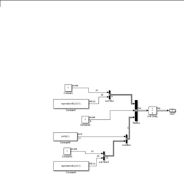
Constant
Sampling Mode
Do not specify a frame-based sampling mode if you specify the Data type to be a bus object.
Example of Using a Bus Object for a Constant Block
The following example illustrates how using a bus object as an output data type for a Constant block can help to simplify a model.
1Open the busic_example model and update it.
This model uses six Constant blocks. For details about the model, see “Examples of Partial Structures”.
2Open the constantbus_example model and update it. This model uses one Constant block that replaces the six Constant blocks in the busic_example model.
2-188

Constant
3Simulate the constantbus_example model. To verify that the output from the Constant block reflects the values from constant_value_struct, perform the next two steps.
4At the MATLAB command line, examine the constant_value_struct structure that the Constant block uses for its Constant value parameter.
constant_value_struct
constant_value_struct =
A:[1x1 struct]
B:5
C:[1x1 struct]
5Examine the logged data in the logsout variable, focusing on the B element of the A1 bus signal. The constant_value_struct structure sets the B element to 5.
logsout.A1.B.Data
Setting Configuration Parameters to Support Using a Bus Object Data Type
To enable the use of a bus object as an output data type, before you start a simulation, set the following diagnostics as indicated:
2-189

Constant
|
|
• In the Diagnostics > |
Connectivity pane of the Configuration |
|
|
|
Parameters dialog box, set “Mux blocks used to create bus signals” to |
||
|
|
error. |
|
|
|
|
• In the Diagnostics > |
Data Validity pane of the Configuration |
|
|
|
Parameters dialog box, set “Underspecified initialization detection” |
||
|
|
to simplified. |
|
|
|
|
The documentation for these diagnostics explains how to convert your |
||
|
|
model to handle error messages the diagnostics generate. |
||
|
|
Arrays of Buses Not Supported |
||
|
|
You cannot use an array of buses with a Constant block. |
||
Examples |
The following Simulink examples show how to use the Constant block: |
|||
|
|
• sldemo_auto_climatecontrol |
||
|
|
• sldemo_boiler |
|
|
|
|
• sldemo_bounce |
|
|
Characteristics |
|
|
|
|
|
Direct Feedthrough |
|
N/A |
|
|
|
Sample Time |
|
Specified in the Sample time parameter |
|
|
Scalar Expansion |
|
No |
|
|
Dimensionalized |
|
Yes |
|
|
Multidimensionalized |
|
Yes |
|
|
Zero-Crossing Detection |
|
No |
See Also |
|
Enumerated Constant |
|
|
2-190

Coulomb and Viscous Friction
Purpose |
Model discontinuity at zero, with linear gain elsewhere |
Library Discontinuities
Description The Coulomb and Viscous Friction block models Coulomb (static) and viscous (dynamic) friction. The block models a discontinuity at zero and a linear gain otherwise.
The block output matches the MATLAB result for:
Data Type
Support
y = sign(x) .* (Gain .* abs(x) + Offset)
where y is the output, x is the input, Gain is the signal gain for nonzero input values, and Offset is the Coulomb friction.
The block accepts one input and generates one output. The input can be a scalar, vector, or matrix with real and complex elements.
•For a scalar input, Gain and Offset can have dimensions that differ from the input. The output is a scalar, vector, or matrix depending on the dimensions of Gain and Offset.
•For a vector or matrix input, Gain and Offset must be scalar or have the same dimensions as the input. The output is a vector or matrix of the same dimensions as the input.
The Coulomb and Viscous Friction block supports real inputs of the following data types:
•Floating point
•Built-in integer
•Fixed point
The block supports complex inputs only for floating-point data types, double and single. The output uses the same data type as the input.
For more information, see “Data Types Supported by Simulink” in the Simulink documentation.
2-191

Coulomb and Viscous Friction
Parameters and Dialog Box
Coulomb friction value
Specify the offset that applies to all input values.
Coefficient of viscous friction
Specify the signal gain for nonzero input values.
2-192
Coulomb and Viscous Friction
Examples |
Scalar Input |
|
Suppose that you have the following model: |
In this model, block input x and Gain are scalar values, but Offset is a vector. Therefore, the block uses element-wise scalar expansion to compute the output.
Vector Input
Suppose that you have the following model:
In this model, vector dimensions for block input x and Offset are the same.
2-193
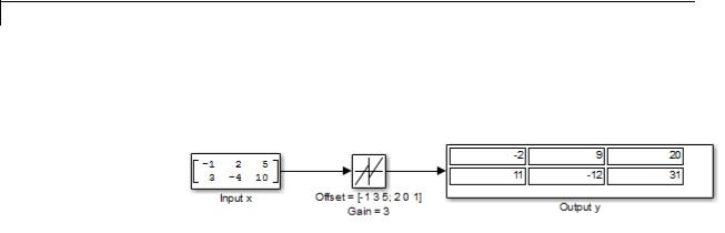
Coulomb and Viscous Friction
Matrix Input
Suppose that you have the following model:
In this model, matrix dimensions for block input x and Offset are the same.
Characteristics |
Direct Feedthrough |
Yes |
|
Sample Time |
Inherited from the driving block |
|
|
|
|
Scalar Expansion |
Yes |
|
Dimensionalized |
Yes |
|
Multidimensionalized |
No |
|
Zero-Crossing Detection |
No |
|
|
|
2-194

Counter Free-Running
Purpose |
Count up and overflow back to zero after reaching maximum value |
|
for specified number of bits |
Library |
Sources |
Description |
The Counter Free-Running block counts up until reaching the maximum |
|
value, 2Nbits – 1, where Nbits is the number of bits. Then the counter |
|
overflows to zero and begins counting up again. |
|
After overflow, the counter always initializes to zero. However, if you |
|
select the global doubles override, the Counter Free-Running block |
|
does not wrap back to zero. |
Data Type |
The Counter Free-Running block outputs an unsigned integer. |
Support |
For more information, see “Data Types Supported by Simulink” in the |
|
Simulink documentation. |
2-195

Counter Free-Running
Parameters and Dialog Box
Number of Bits
Specify the number of bits.
When you |
Such as... |
The block counts |
Which |
use... |
|
up to... |
is... |
A positive |
8 |
28 – 1 |
255 |
integer |
|
|
|
An unsigned |
uint8(8) |
uint8(2uint8(8) – 1) |
254 |
integer |
|
|
|
expression |
|
|
|
2-196

Counter Free-Running
Sample time
Specify the time interval between samples. To inherit the sample time, set this parameter to -1. See “Specify Sample Time” in the Simulink documentation.
Examples Bit Specification Using a Positive Integer
Suppose that you have the following model:
The block parameters are:
|
Parameter |
|
Setting |
|
|
Number of Bits |
|
8 |
|
|
Sample time |
|
-1 |
|
|
The solver options for the model are: |
|
|
|
|
|
|
|
|
|
Parameter |
|
Setting |
|
|
Stop time |
|
255 |
|
|
Type |
|
Fixed-step |
|
|
Solver |
|
discrete (no continuous |
|
|
|
|
states) |
|
|
Fixed-step size |
|
1 |
|
|
|
|
|
|
At t = 255, the counter reaches the maximum value: 28 – 1
2-197

Counter Free-Running
If you change the stop time of the simulation to 256, the counter wraps to zero.
Bit Specification Using an Unsigned Integer Expression
Suppose that you have the following model:
The block parameters are:
|
Parameter |
Setting |
|
|
Number of Bits |
uint8(8) |
|
|
Sample time |
-1 |
|
|
|
|
|
The solver options for the model are:
|
Parameter |
Setting |
|
|
Stop time |
254 |
|
|
Type |
Fixed-step |
|
|
Solver |
discrete (no continuous |
|
|
|
states) |
|
|
Fixed-step size |
1 |
|
|
|
|
|
At t = 254, the counter reaches the maximum value:
uint8(2uint8(8) – 1)
If you change the stop time of the simulation to 255, the counter wraps to zero.
2-198

Counter Free-Running
Characteristics |
|
Sample Time |
Specified in the Sample time parameter |
|
|
Scalar Expansion |
No |
|
|
Zero-Crossing Detection |
No |
See Also |
|
Counter Limited |
|
2-199

Counter Limited
Purpose |
Count up and wrap back to zero after outputting specified upper limit |
Library |
Sources |
Description |
The Counter Limited block counts up until the specified upper limit is |
|
reached. Then the counter wraps back to zero, and restarts counting |
|
up. The counter always initializes to zero. |
|
You can specify the upper limit with the Upper limit parameter. |
|
You can specify the sample time with the Sample time parameter. A |
|
Sample time of -1 means that the sample time is inherited. |
|
The output is an unsigned integer of 8, 16, or 32 bits, with the smallest |
|
number of bits needed to represent the upper limit. |
Data Type |
The Counter Limited block outputs an unsigned integer. |
Support |
For more information, see “Data Types Supported by Simulink” in the |
|
Simulink documentation. |
2-200

Counter Limited
Parameters and Dialog Box
Examples
Upper limit
Specify the upper limit.
Sample time
Specify the time interval between samples. To inherit the sample time, set this parameter to -1. See “Specify Sample Time” in the Simulink documentation.
The following Simulink examples show how to use the Counter Limited block:
• sldemo_tonegen_fixpt
2-201

Counter Limited
Characteristics |
|
Sample Time |
Specified in the Sample time parameter |
|
|
Scalar Expansion |
No |
See Also |
|
Counter Free-Running |
|
2-202
Data Store Memory
Purpose |
Define data store |
Library |
Signal Routing |
Description |
The Data Store Memory block defines and initializes a named shared |
|
data store, which is a memory region usable by Data Store Read and |
|
Data Store Write blocks that specify the same data store name. |
|
The location of the Data Store Memory block that defines a data store |
|
determines which Data Store Read and Data Store Write blocks can |
|
access the data store: |
|
• If the Data Store Memory block is in the top-level system, Data Store |
|
Read and Data Store Write blocks anywhere in the model can access |
|
the data store. |
|
• If the Data Store Memory block is in a subsystem, Data Store Read |
|
and Data Store Write blocks in the same subsystem or in any |
|
subsystem below it in the model hierarchy can access the data store. |
|
Data Store Read or Data Store Write blocks cannot access a Data Store |
|
Memory block that is either in a model that contains a Model block |
|
or in a referenced model. |
|
Do not include a Data Store Memory block in a subsystem that a For |
|
Each Subsystem block represents. |
|
Use the Initial value parameter to initialize the data store. Specify |
|
a scalar value or an array of values in the Initial value parameter. |
|
The dimensions of the array determine the dimensionality of the data |
|
store. Any data written to the data store must have the dimensions |
|
designated by the Initial value parameter. Otherwise, an error occurs. |
|
Obtaining correct results from data stores requires ensuring that data |
|
store reads and writes occur in the expected order. For details, see: |
|
• “Order Data Store Access” |
|
• “Data Store Diagnostics” |
2-203

Data Store Memory
Data Type
Support
• “Log Data Stores”
You can use Simulink.Signal objects in addition to, or instead of, Data Store Memory blocks to define data stores. A data store defined in the base workspace with a signal object is a global data store. Global data stores are accessible to every model, including all referenced models. See “Data Stores” for more information.
The Data Store Memory block stores real or complex signals of any data type that Simulink supports, including fixed-point, bus object, and enumerated data types.
Note If you specify a bus object as the data type for this block, do not set the minimum and maximum values for bus data on the
block. Simulink ignores these settings. Instead, set the minimum and maximum values for bus elements of the bus object specified as the data type. The values should be finite real double scalar.
For information on the Minimum and Maximum properties of a bus element, see Simulink.BusElement.
For more information, see “Data Types Supported by Simulink” in the Simulink documentation.
You can use arrays of buses with a Data Store Memory block. For details about defining and using an array of buses, see “Combine Buses into an Array of Buses”.
2-204

Data Store Memory
Parameters |
The Main pane of the Data Store Memory block dialog box appears |
and |
as follows: |
Dialog |
|
Box |
|
2-205

Data Store Memory
Data store name
Specify a name for the data store you are defining with this block. Data Store Read and Data Store Write blocks with the same name can read from, and write to, the data store initialized by this block. The name can represent a Data Store Memory block or a sign object defined to be a data store.
Corresponding Data Store Read/Write blocks
List all the Data Store Read and Data Store Write blocks that have the same data store name as the current block, and that are in the current system or in any subsystem below it in the model hierarchy. Double-click a block in this list to highlight the block and bring it to the foreground.
The Signal Attributes pane of the Data Store Memory block dialog box appears as follows:
2-206

Data Store Memory
2-207

Data Store Memory
Initial value
Specify the initial value or values of the data store. The dimensions of this value determine the dimensions of data that may be written to the data store. The Minimum parameter specifies the minimum value for this parameter, and the Maximum parameter specifies the maximum value.
Initial value dimensions must match the dimensions that you specify in the Signal Attributes > Dimensions parameter, unless the initial value is a MATLAB structure.
Minimum
Specify the minimum value that the block should output. The default value is [] (unspecified). This number must be a finite real double scalar value.
Note If you specify a bus object as the data type for this block, do not set the minimum value for bus data on the block. Simulink ignores this setting. Instead, set the minimum values for bus elements of the bus object specified as the data type. For information on the Minimum property of a bus element, see
Simulink.BusElement.
Simulink uses the minimum value to perform:
•Parameter range checking (see “Check Parameter Values”)
•Simulation range checking (see “Signal Ranges”)
•Automatic scaling of fixed-point data types
Maximum
Specify the maximum value that the block should output. The default value is [] (unspecified). This number must be a finite real double scalar value.
2-208

Data Store Memory
Note If you specify a bus object as the data type for this block, do not set the maximum value for bus data on the block. Simulink ignores this setting. Instead, set the maximum values for bus elements of the bus object specified as the data type. For information on the Maximum property of a bus element, see
Simulink.BusElement.
Simulink uses the maximum value to perform:
•Parameter range checking (see “Check Parameter Values”)
•Simulation range checking (see “Signal Ranges”)
•Automatic scaling of fixed-point data types
Data type
Specify the output data type. You can set it to:
•A rule that inherits a data type (for example, Inherit: auto)
•The name of a built-in data type (for example, single)
•The name of a data type object (for example, a
Simulink.NumericType object)
•An expression that evaluates to a data type (for example, fixdt(1,16,0)). Do not specify a bus object as the data type in an expression; use Bus: <object name> to specify a bus data type.
•Bus: <object name>; enter the name of a bus object that you want to use to define the structure of the bus. The bus must be a nonvirtual bus. If you need to create or change a bus object, click the Show data type assistant button and then click the Edit button to the right of the Bus object field to open the Simulink Bus Editor. For details about the Bus Editor, see “Manage Bus Objects with the Bus Editor”
2-209

Data Store Memory
Click the Show data type assistant button  to display the Data Type Assistant, which helps you set the Data type parameter.
See “Specify Block Output Data Types”.
Lock output data type setting against changes by the fixed-point tools
Select to lock the output data type setting of this block against changes by the Fixed-Point Tool and the Fixed-Point Advisor. For more information, see “Use Lock Output Data Type Setting”.
Signal type
Specify the numeric type, real or complex, of the values in the data store.
Dimensions (-1 to infer from Initial value)
Specify dimensions that match the dimensions of the Initial value dimensions, unless you specify a MATLAB structure for the initial value. For example, if you use a MATLAB structure for the initial value, then you need to specify dimensions to initialize an array of buses with this MATLAB structure.
Interpret vector parameters as 1-D
If you enable this option and specify the Initial value parameter as a column or row matrix, Simulink initializes the data store to a 1-D array whose elements are equal to the elements of the row or column vector. See “Determining the Output Dimensions of Source Blocks”.
Data store must resolve to Simulink signal object
Specify that Simulink software, when compiling the model, searches the model and base workspace for a Simulink.Signal object having the same name, as described in “Symbol Resolution”. If Simulink does not find such an object, the compilation stops, with an error. Otherwise, Simulink compares the attributes of the signal object to the corresponding attributes of the Data Store Memory block. If the block and the object attributes are
2-210

Data Store Memory
inconsistent, Simulink halts model compilation and displays an error.
Package
Select a package that defines the custom storage class you want to apply. If you have defined any packages of your own, click Refresh. This action adds all user-defined packages on your search path to the package list.
Storage class
Select a custom storage class for the signal object. When no Package is selected, setting this parameter to ExportedGlobal,
ImportedExtern, or ImportedExternPointer enables Storage type qualifier.
Storage type qualifier
Specify the Simulink Coder storage type qualifier.
See “States” in the Simulink Coder documentation for more information.
The Diagnostics pane of the Data Store Memory block dialog box appears as follows:
2-211

Data Store Memory
2-212
Data Store Memory
Detect read before write
Select the diagnostic action to take if the model attempts to read data from a data store to which it has not written data in this time step. See also the “Detect read before write” diagnostic in the
Data Store Memory Block section of the Model Configuration Parameters > Diagnostics > Data Validity pane.
Default: warning
none
Take no action.
warning
Display a warning.
error
Terminate the simulation and display an error message.
Detect write after read
Select the diagnostic action to take if the model attempts to write data to the data store after previously reading data from it in the current time step. See also the “Detect write after read” diagnostic in the Data Store Memory Block section of the
Model Configuration Parameters > Diagnostics > Data Validity pane.
Default: warning
none
Take no action.
warning
Display a warning.
error
Terminate the simulation and display an error message.
2-213

Data Store Memory
Detect write after write
Select the diagnostic action to take if the model attempts to write data to the data store twice in succession in the current time step. See also the “Detect write after write” diagnostic in the Data Store Memory Block section of the Model Configuration Parameters > Diagnostics > Data Validity pane.
Default: warning
none
Take no action.
warning
Display a warning.
error
Terminate the simulation and display an error message.
The Logging pane of the Data Store Memory block dialog box appears as follows:
2-214

Data Store Memory
2-215

Data Store Memory
Log signal data
Select this option to save the values of this signal to the MATLAB workspace during simulation. See “Signal Logging” for details.
Logging name
Use this pair of controls, consisting of a list box and an edit field, to specify the name associated with logged signal data.
Simulink uses the signal name as its logging name by default. To specify a custom logging name, select Custom from the list box and enter the custom name in the adjacent edit field.
Data
Use this group of controls to limit the amount of data that Simulink logs for this signal.
•Limit data points to last: Discard all but the last N data points, where N is the number that you enter in the adjacent edit field.
•Decimation: Log every Nth data point, where N is the number that you enter in the adjacent edit field. For example, suppose that your model uses a fixed-step solver with a step size of 0.1 s. If you select this option and accept the default decimation value (2), Simulink records data points for this signal at times 0.0, 0.2, 0.4, and so on.
For more information, see “Log Data Stores”
Characteristics
See Also
Sample Time |
N/A |
Dimensionalized |
Yes |
Multidimensionalized |
Yes |
|
|
•“Data Stores”
•“Access Data Stores with Simulink Blocks”
•Data Store Read
2-216

Data Store Memory
•Data Store Write
•“Log Data Stores”
2-217

Data Store Read
Purpose |
Read data from data store |
Library |
Signal Routing |
Description |
The Data Store Read block copies data from the named data store to |
|
its output. More than one Data Store Read block can read from the |
|
same data store. |
|
The data store from which the data is read is determined by the location |
|
of the Data Store Memory block or signal object that defines the data |
|
store. For more information, see “Data Stores” and Data Store Memory. |
|
Obtaining correct results from data stores requires ensuring that data |
|
store reads and writes occur in the expected order. See “Order Data |
|
Store Access” and “Data Store Diagnostics” for details. |
Data Type |
The Data Store Read block can output a real or complex signal of any |
Support |
data type that Simulink supports, including fixed-point, bus object, |
|
and enumerated data types. |
|
For more information, see “Data Types Supported by Simulink” in the |
|
Simulink documentation. |
|
You can use arrays of buses with a Data Store Read block. For details |
|
about defining and using an array of buses, see “Combine Buses into |
|
an Array of Buses”. |
2-218

Data Store Read
Parameters |
The Parameters pane of the Data Store Read block dialog box appears |
and |
as follows: |
Dialog |
|
Box |
|
Data store name
Specifies the name of the data store from which this block reads data. The adjacent pull-down list lists the names of Data Store Memory blocks that exist at the same level in the model as the Data Store Read block or at higher levels. The pulldown list also includes all Simulink.Signal objects in the base and model workspaces. To change the name, select a name from the pull-down list or enter the name directly in the edit field.
When Simulink software compiles the model containing this block, Simulink software searches the model upwards from this block’s level for a Data Store Memory block having the specified data store name. If Simulink software does not find such a block, it searches the model workspace and the MATLAB workspace for
2-219

Data Store Read
a Simulink.Signal object having the same name. See “Symbol Resolution” for more information about the search path.
If Simulink software finds the signal object, it creates a hidden Data Store Memory block at the model’s root level having the properties specified by the signal object and an initial value of 0. If Simulink software finds neither the Data Store Memory block nor the signal object, it halts the compilation and displays an error.
Data store memory block
This field lists the Data Store Memory block that initialized the store from which this block reads.
Data store write blocks
This parameter lists all the Data Store Write blocks with the same data store name as this block that are in the same (sub)system or in any subsystem below it in the model hierarchy. Double-click any entry on this list to highlight the block and bring it to the foreground.
Sample time
The sample time, which controls when the block reads from the data store. A value of -1 indicates that the sample time is inherited. See “Specify Sample Time” for more information.
The Element Selection pane of the Data Store Read block dialog box appears as follows:
2-220

Data Store Read
Use the Element Selection pane to select a subset of the bus or matrix elements defined for the associated data store. The Data Store Read block icon reflects the elements that you specify. For details, see “Accessing Specific Bus and Matrix Elements”.
Elements in the array or Signals in the bus (Prompt is specific to the type of data.)
For bus signals, lists the elements in the associated data store. The list displays the maximum dimensions for each element, in parentheses.
For data stores with a bus data type, you can expand the tree to view the bus elements. For data stores with arrays, you can read the whole data store, or you can specify one or more elements
of the whole data store.
You can select an element and then use one of the following approaches:
2-221

Data Store Read
•Click Select>> to display that element (and all its subelements) in the Selected element(s) list.
•Use the Specify element(s) to select edit box to specify the bus or matrix elements that you want to select for reading. Then click Select>>.
To refresh the display to reflect modifications to the bus or matrix used in the data store, click Refresh.
Specify element(s) to select
Enter a MATLAB expression to define the specific element that you want to read. For example, for a data store named DSM that has maximum dimensions of [3,5], you could enter expressions such as DSM(2, 4) or DSM([1 3], 2) in the edit box and then click Select>>.
To apply the element selection, click OK.
Selected Element(s)
Displays the elements that you select. The Data Store Read block icon displays a port for each element that you specify.
To change the order of bus or matrix elements in the list, select the element in the list and click Up or Down. Changing the order of the elements in the list changes the order of the ports. To remove an element, click Remove.
Characteristics
See Also
Sample Time |
Specified in the Sample time parameter |
Dimensionalized |
Yes |
Multidimensionalized |
Yes |
|
|
•“Data Stores”
•“Access Data Stores with Simulink Blocks”
•Data Store Memory
2-222
Data Store Read
• Data Store Write
2-223

Data Store Write
Purpose |
Write data to data store |
Library |
Signal Routing |
Description |
The Data Store Write block copies the value at its input to the named |
|
data store. Each write operation performed by a Data Store Write block |
|
writes over the data store, replacing the previous contents. |
|
The data store to which this block writes is determined by the location |
|
of the Data Store Memory block or signal object that defines the data |
|
store. For more information, see “Data Stores” and Data Store Memory. |
|
The size of the data store is set by the signal object or the Data Store |
|
Memory block that defines and initializes the data store. Each Data |
|
Store Write block that writes to that data store must write the same |
|
amount of data. |
|
More than one Data Store Write block can write to the same data store. |
|
However, if two Data Store Write blocks attempt to write to the same |
|
data store during the same simulation step, results are unpredictable. |
|
Obtaining correct results from data stores requires ensuring that data |
|
store reads and writes occur in the expected order. For details, see |
|
“Order Data Store Access” and “Data Store Diagnostics”. |
|
You can log the values of a local or global data store data variable for all |
|
the steps in a simulation. For details, see “Log Data Stores”. |
Data Type |
The Data Store Write block accepts a real or complex signal of any |
Support |
data type that Simulink supports, including fixed-point, bus object, |
|
and enumerated data types. |
|
For more information, see “Data Types Supported by Simulink” in the |
|
Simulink documentation. |
|
You can use an array of buses with a Data Store Write block. For details |
|
about defining and using an array of buses, see “Combine Buses into |
|
an Array of Buses”. |
2-224

Data Store Write
Parameters |
The Parameters pane of the Data Store Write block dialog box appears |
and |
as follows: |
Dialog |
|
Box |
|
Data store name
Specifies the name of the data store to which this block writes data. The adjacent pull-down list lists the names of Data Store Memory blocks that exist at the same level in the model as the Data Store Write block or at higher levels. The pulldown list also includes all Simulink.Signal objects in the base and model workspaces. To change the name, select a name from the pull-down list or enter the name directly in the edit field.
When Simulink software compiles the model containing this block, Simulink software searches the model upwards from this block’s level for a Data Store Memory block having the specified data store name. If Simulink does not find such a block, it searches the model workspace and the MATLAB workspace for
2-225

Data Store Write
a Simulink.Signal object having the same name. See “Symbol Resolution” for more information about the search path.
If Simulink finds the signal object, it creates a hidden Data Store Memory block at the model’s root level having the properties specified by the signal object and an initial value of 0. If Simulink software finds neither the Data Store Memory block nor the signal object, it halts the compilation and displays an error.
Data store memory block
This field lists the Data Store Memory block that initialized the store to which this block writes.
Data store read blocks
This parameter lists all the Data Store Read blocks with the same data store name as this block that are in the same (sub)system or in any subsystem below it in the model hierarchy. Double-click any entry on this list to highlight the block and bring it to the foreground.
Sample time
Specify the sample time that controls when the block writes to the data store. A value of -1 indicates that the sample time is inherited. See “Specify Sample Time” for more information.
The Element Assignment pane of the Data Store Write block dialog box appears as follows:
2-226

Data Store Write
Use the Element Assignment pane to assign a subset of the bus or matrix elements defined for writing to the associated data store. The Data Store Write block icon reflects the elements that you specify. For details, see “Accessing Specific Bus and Matrix Elements”.
Elements in the array or Signals in the bus (Prompt is specific to the type of data.)
For bus signals, lists the elements in the associated data store. The list displays the maximum dimensions for each element, in parentheses.
For data stores with a bus data type, you can expand the tree to view the bus elements. For data stores with arrays, you can write the whole data store, or you can assign one or more elements to the whole data store.
You can select an element and then use one of the following approaches:
2-227

Data Store Write
•Click Select>> to display that element (and all its subelements) in the Assigned element(s) list.
•Use the Specify element(s) to assign edit box to specify the bus or matrix elements that you want to select for reading. Then click Select>>.
To refresh the display to reflect modifications to the bus or matrix used in the data store, click Refresh.
Specify element(s) to assign
Enter a MATLAB expression to define the specific element that you want to write. For example, for a data store named DSM that has maximum dimensions of [3,5], you could enter expressions such as DSM(2, 4) or DSM([1 3], 2) in the edit box. Then click
Select>>.
To apply the element selection, click OK.
Assigned Element(s)
Displays the elements that you selected for assignment. The Data Store Write block icon displays a port for each element that you specify.
To change the order of bus or matrix elements in the list, select the element in the list and click Up or Down. Changing the order of the elements in the list changes the order of the ports. To remove an element, click Remove.
Characteristics
See Also
Sample Time |
Specified in the Sample time parameter |
Dimensionalized |
Yes |
Multidimensionalized |
Yes |
|
|
•“Data Stores”
•“Access Data Stores with Simulink Blocks”
2-228

Data Store Write
•Data Store Memory
•Data Store Read
•“Log Data Stores”
2-229

Data Type Conversion
Purpose |
Convert input signal to specified data type |
Library |
Signal Attributes |
Description |
|
The Data Type Conversion block converts an input signal of any Simulink data type to the data type you specify for the Output data type parameter. The input can be any realor complex-valued signal. If the input is real, the output is real. If the input is complex, the output is complex.
Note This block requires that you specify the data type and scaling for the conversion. If you want to inherit the data type or scaling from an input signal, use the Data Type Conversion Inherited block.
The Input and output to have equal parameter controls how the block handles the input. The possible values are Real World Value (RWV), which is the default value, and Stored Integer (SI):
•Select Real World Value (RWV) to treat the input as V = SQ + B, where S is the slope and B is the bias. V is used to produce Q = (V – B)/S, which is stored in the output.
•Select Stored Integer (SI) to treat the input as a stored integer, Q. The value of Q is directly used to produce the output. In this mode, the input and output are identical, except that the input is a raw integer lacking proper scaling information. Selecting Stored Integer might be useful in the following cases:
2-230

Data Type Conversion
-Generating code for a fixed-point processor
The resulting code uses only integers and does not use floating-point operations.
-Partitioning your model based on hardware characteristics
For example, part of your model might involve simulating hardware that produces integers as output.
Note When casting NaN values of type double to boolean, the Data Type Conversion block casts to boolean true.
Casting Enumerated Signals
Use a Data Type Conversion block to cast enumerated signals as follows.
1To cast a signal of enumerated type to a signal of any numeric type
The underlying integers of all enumerated values input to the Data Type Conversion block should be within the range of the numeric type; otherwise, an error occurs during simulation.
2To cast a signal of any integer type to a signal of enumerated type
The value input to the Data Type Conversion block should match the underlying value of an enumerated value; otherwise, an error occurs during simulation.
You can enable the block’s Saturate on integer overflow parameter so that Simulink uses the default value of the enumerated type when the value input to the block does not match the underlying value of an enumerated value. See “Type Casting for Enumerations”.
You cannot use a Data Type Conversion block in the following cases.
• To cast a non-integer numeric signal to an enumerated signal
2-231

Data Type Conversion
Data Type
Support
•To cast a complex signal to an enumerated signal, regardless of the data types of the complex signal’s real and imaginary parts.
See “About Simulink Enumerations” for information on working with enumerated types.
The Data Type Conversion block handles any data type that Simulink supports, including fixed-point and enumerated data types.
For more information, see “Data Types Supported by Simulink” in the Simulink documentation.
2-232
Data Type Conversion
Parameters and Dialog Box
2-233

Data Type Conversion
Show data type assistant
Display the Data Type Assistant.
Settings
The Data Type Assistant helps you set the Output data type parameter.
For more information, see “Specify Block Output Data Types”.
Command-Line Information
See “Block-Specific Parameters” on page 8-109 for the command-line information.
2-234

Data Type Conversion
Lock output data type setting against changes by the fixed-point tools
Select to lock the output data type setting of this block against changes by the Fixed-Point Tool and the Fixed-Point Advisor.
Settings
Default: Off
 On
On
Locks the output data type setting for this block.
 Off
Off
Allows the Fixed-Point Tool and the Fixed-Point Advisor to change the output data type setting for this block.
Command-Line Information
See “Block-Specific Parameters” on page 8-109 for the command-line information.
See Also
For more information, see “Use Lock Output Data Type Setting”.
2-235

Data Type Conversion
Input and output to have equal
Specify which type of input and output should be equal.
Settings
Default: Real World Value (RWV)
Real World Value (RWV)
Specifies the goal of making the Real World Value (RWV) of the input equal to the Real World Value (RWV) of the output.
Stored Integer (SI)
Specifies the goal of making the Stored Integer (SI) value of the input equal to the Stored Integer (SI) value of the output.
Command-Line Information
See “Block-Specific Parameters” on page 8-109 for the command-line information.
2-236

Data Type Conversion
Integer rounding mode
Specify the rounding mode for fixed-point operations.
Settings
Default: Floor
Ceiling
Rounds both positive and negative numbers toward positive infinity. Equivalent to the MATLAB ceil function.
Convergent
Rounds number to the nearest representable value. If a tie occurs, rounds to the nearest even integer. Equivalent to the Fixed-Point Toolbox™ convergent function.
Floor
Rounds both positive and negative numbers toward negative infinity. Equivalent to the MATLAB floor function.
Nearest
Rounds number to the nearest representable value. If a tie occurs, rounds toward positive infinity. Equivalent to the Fixed-Point Toolbox nearest function.
Round
Rounds number to the nearest representable value. If a tie occurs, rounds positive numbers toward positive infinity and rounds negative numbers toward negative infinity. Equivalent to the Fixed-Point Toolbox round function.
Simplest
Automatically chooses between round toward floor and round toward zero to generate rounding code that is as efficient as possible.
Zero
Rounds number toward zero. Equivalent to the MATLAB fix function.
2-237

Data Type Conversion
Command-Line Information
See “Block-Specific Parameters” on page 8-109 for the command-line information.
See Also
For more information, see “Rounding” in the Simulink Fixed Point documentation.
2-238

Data Type Conversion
Saturate on integer overflow
Specify whether overflows saturate.
Settings
Default: Off
 On
On
Overflows saturate to either the minimum or maximum value that the data type can represent.
For example, an overflow associated with a signed 8-bit integer can saturate to -128 or 127.
 Off
Off
Overflows wrap to the appropriate value that is representable by the data type.
For example, the number 130 does not fit in a signed 8-bit integer and wraps to -126.
Tips
•Consider selecting this check box when your model has possible overflow and you want explicit saturation protection in the generated code.
•Consider clearing this check box when you want to optimize efficiency of your generated code.
Clearing this check box also helps you avoid overspecifying how a block handles out-of-range signals. For more information, see “Checking for Signal Range Errors”.
•When you select this check box, saturation applies to every internal operation on the block, not just the output or result.
•In general, the code generation process can detect when overflow is not possible. In this case, the code generator does not produce saturation code.
2-239

Data Type Conversion
Command-Line Information
See “Block-Specific Parameters” on page 8-109 for the command-line information.
2-240

Data Type Conversion
Sample time (-1 for inherited)
Enter the discrete interval between sample time hits or specify another appropriate sample time such as continuous or inherited.
Settings
Default: -1
By default, the block inherits its sample time based upon the context of the block within the model. To set a different sample time, enter a valid sample time based upon the table in “Types of Sample Time”.
See also “Specify Sample Time” in the online documentation for more information.
Command-Line Information
See “Block-Specific Parameters” on page 8-109 for the command-line information.
2-241

Data Type Conversion
Output minimum
Specify the minimum value that the block should output.
Settings
Default: [] (unspecified)
This number must be a finite real double scalar value.
Note If you specify a bus object as the data type for this block, do not set the minimum value for bus data on the block. Simulink ignores this setting. Instead, set the minimum values for bus elements of the bus object specified as the data type. For information on the Minimum property of a bus element, see Simulink.BusElement.
Simulink uses the minimum to perform:
•Parameter range checking (see “Check Parameter Values”) for some blocks
•Simulation range checking (see “Signal Ranges”)
•Automatic scaling of fixed-point data types
Command-Line Information
See “Block-Specific Parameters” on page 8-109 for the command-line information.
2-242
Data Type Conversion
Output maximum
Specify the maximum value that the block should output.
Settings
Default: [] (unspecified)
This number must be a finite real double scalar value.
Note If you specify a bus object as the data type for this block, do not set the maximum value for bus data on the block. Simulink ignores this setting. Instead, set the maximum values for bus elements of the bus object specified as the data type. For information on the Maximum property of a bus element, see Simulink.BusElement.
Simulink uses the maximum value to perform:
•Parameter range checking (see “Check Parameter Values”) for some blocks
•Simulation range checking (see “Signal Ranges”)
•Automatic scaling of fixed-point data types
Command-Line Information
See “Block-Specific Parameters” on page 8-109 for the command-line information.
2-243

Data Type Conversion
Output data type
Specify the output data type.
Settings
Default: Inherit: Inherit via back propagation
Inherit: Inherit via back propagation
Use data type of the driving block.
double
Output data type is double.
single
Output data type is single.
int8
Output data type is int8.
uint8
Output data type is uint8.
int16
Output data type is int16.
uint16
Output data type is uint16.
int32
Output data type is int32.
uint32
Output data type is uint32.
boolean
Output data type is boolean.
fixdt(1,16,0)
Output data type is fixed point fixdt(1,16,0).
fixdt(1,16,2^0,0)
Output data type is fixed point fixdt(1,16,2^0,0).
2-244

Data Type Conversion
Enum: <class name>
Use an enumerated data type, for example, Enum: BasicColors.
<data type expression>
Use a data type object, for example, Simulink.NumericType.
Command-Line Information
See “Block-Specific Parameters” on page 8-109 for the command-line information.
See Also
For more information, see “Specify Block Output Data Types”.
2-245

Data Type Conversion
Mode
Select the category of data to specify.
Settings
Default: Inherit
Inherit
Inheritance rules for data types. Selecting Inherit enables
Inherit via back propagation.
Built in
Built-in data types. Selecting Built in enables a second menu/text box to the right. Select one of the following choices:
•double (default)
•single
•int8
•uint8
•int16
•uint16
•int32
•uint32
•boolean
Fixed point
Fixed-point data types.
Enumerated
Enumerated data types. Selecting Enumerated enables a second menu/text box to the right, where you can enter the class name.
Expression
Expressions that evaluate to data types. Selecting Expression enables a second menu/text box to the right, where you can enter the expression.
2-246

Data Type Conversion
Dependency
Clicking the Show data type assistant button enables this parameter.
Command-Line Information
See “Block-Specific Parameters” on page 8-109 for the command-line information.
See Also
See “Specify Data Types Using Data Type Assistant”.
2-247

Data Type Conversion
Data type override
Specify data type override mode for this signal.
Settings
Default: Inherit
Inherit
Inherits the data type override setting from its context, that is, from the block, Simulink.Signal object or Stateflow chart in Simulink that is using the signal.
Off
Ignores the data type override setting of its context and uses the fixed-point data type specified for the signal.
Tip
The ability to turn off data type override for an individual data type provides greater control over the data types in your model when you apply data type override. For example, you can use this option to ensure that data types meet the requirements of downstream blocks regardless of the data type override setting.
Dependency
This parameter appears only when the Mode is Built in or Fixed point.
2-248

Data Type Conversion
Signedness
Specify whether you want the fixed-point data as signed or unsigned.
Settings
Default: Signed
Signed
Specify the fixed-point data as signed.
Unsigned
Specify the fixed-point data as unsigned.
Dependencies
Selecting Mode > Fixed point enables this parameter.
Command-Line Information
See “Block-Specific Parameters” on page 8-109 for the command-line information.
See Also
For more information, see “Specifying a Fixed-Point Data Type”.
2-249

Data Type Conversion
Word length
Specify the bit size of the word that holds the quantized integer.
Settings
Default: 16
Minimum: 0
Maximum: 32
Dependencies
Selecting Mode > Fixed point enables this parameter.
Command-Line Information
See “Block-Specific Parameters” on page 8-109 for the command-line information.
See Also
For more information, see “Specifying a Fixed-Point Data Type”.
2-250

Data Type Conversion
Scaling
Specify the method for scaling your fixed-point data to avoid overflow conditions and minimize quantization errors.
Settings
Default: Best precision
Binary point
Specify binary point location.
Slope and bias
Enter slope and bias.
Best precision
Specify best-precision values.
Dependencies
Selecting Mode > Fixed point enables this parameter.
Selecting Binary point enables:
•Fraction length
•Calculate Best-Precision Scaling
Selecting Slope and bias enables:
•Slope
•Bias
•Calculate Best-Precision Scaling
Command-Line Information
See “Block-Specific Parameters” on page 8-109 for the command-line information.
See Also
For more information, see “Specifying a Fixed-Point Data Type”.
2-251

Data Type Conversion
Fraction length
Specify fraction length for fixed-point data type.
Settings
Default: 0
Binary points can be positive or negative integers.
Dependencies
Selecting Scaling > Binary point enables this parameter.
Command-Line Information
See “Block-Specific Parameters” on page 8-109 for the command-line information.
See Also
For more information, see “Specifying a Fixed-Point Data Type”.
2-252
Data Type Conversion
Slope
Specify slope for the fixed-point data type.
Settings
Default: 2^0
Specify any positive real number.
Dependencies
Selecting Scaling > Slope and bias enables this parameter.
Command-Line Information
See “Block-Specific Parameters” on page 8-109 for the command-line information.
See Also
For more information, see “Specifying a Fixed-Point Data Type”.
Bias
Specify bias for the fixed-point data type.
Settings
Default: 0
Specify any real number.
Dependencies
Selecting Scaling > Slope and bias enables this parameter.
Command-Line Information
See “Block-Specific Parameters” on page 8-109 for the command-line information.
See Also
For more information, see “Specifying a Fixed-Point Data Type”.
Examples Real World Values Versus Stored Integers
The following model uses the Data Type Conversion block to explain the difference between a real-world value and a stored integer. Consider these two fixed-point block diagrams:
2-253

Data Type Conversion
In the top block diagram, the Data Type Conversion block treats the input as a real-world value, and maps that value to an 8-bit signed generalized fixed-point data type with a scaling of 2-2. When the value is then output from the Data Type Conversion1 block as a real-world value, the scaling and data type information is retained and the output value is 001111.00, or 15. When the value is output from the Data Type Conversion2 block as a stored integer, the scaling and data type information is not retained and the stored integer is interpreted as 00111100, or 60.
In the bottom block diagram, the Data Type Conversion3 block treats the input as a stored integer, and the data type and scaling information
2-254

Data Type Conversion
is not applied. When the value is then output from the Data Type Conversion4 block as a real-world value, the scaling and data type information is applied to the stored integer, and the output value is 000011.11, or 3.75. When the value is output from the Data Type Conversion5 block as a stored integer, you get back the original input value of 15.
Real World Values and Stored Integers in Summations
The following model shows how a summation operation applies to real-world values and stored integers, and how the generated code handles scaling information.
Note that the summation operation produces the correct result when the Data Type Conversion (2 or 5) block outputs a real-world value. This is because the specified scaling information is applied to the stored integer value. However, when the Data Type Conversion4 block outputs
2-255

Data Type Conversion
a stored integer value, then the summation operation produces an unexpected result due to the absence of scaling information.
If you generate code for the above model, then the code captures the appropriate scaling information. The code for the Sum block is shown below. The inputs to this block are tagged with the specified scaling information so that the necessary shifts are performed for the summation operation.
/* Sum Block: <Root>/Sum |
|
|
|
|
* |
|
|
|
|
* y = |
u0 + u1 |
|
|
|
* |
|
|
|
|
* Input0 |
Data Type: |
Fixed Point |
S16 |
2^-2 |
* Input1 |
Data Type: |
Fixed Point |
S16 |
2^-4 |
* Output0 Data Type: |
Fixed Point |
S16 |
2^-5 |
|
* |
|
|
|
|
*Round Mode: Floor
*Saturation Mode: Wrap
*/
sum = ((in1) << 3); sum += ((in2) << 1);
Characteristics |
|
Direct Feedthrough |
Yes |
|
|
Sample Time |
Inherited from driving block |
|
|
Scalar Expansion |
N/A |
|
|
Dimensionalized |
Yes |
|
|
Multidimensionalized |
Yes |
|
|
Zero-Crossing Detection |
No |
See Also |
|
Data Type Conversion Inherited |
|
2-256

Data Type Conversion Inherited
Purpose |
Convert from one data type to another using inherited data type and |
|
scaling |
Library |
Signal Attributes |
Description |
|
|
The Data Type Conversion Inherited block forces dissimilar data types |
|
to be the same. The first input is used as the reference signal and |
|
the second input is converted to the reference type by inheriting the |
|
data type and scaling information. (See “How to Rotate a Block” in the |
|
Simulink documentation for a description of the port order for various |
|
block orientations.) Either input undergoes scalar expansion such that |
|
the output has the same width as the widest input. |
|
Inheriting the data type and scaling provides these advantages: |
|
• It makes reusing existing models easier. |
|
• It allows you to create new fixed-point models with less effort since |
|
you can avoid the detail of specifying the associated parameters. |
Data Type |
The Data Type Conversion Inherited block accepts signals of the |
Support |
following data types: |
|
• Floating point |
|
• Built-in integer |
|
• Fixed point |
|
• Boolean |
|
• Enumerated |
2-257

Data Type Conversion Inherited
Parameters and Dialog Box
For more information, see “Data Types Supported by Simulink” in the Simulink documentation.
Input and Output to have equal
Specify whether the Real World Value (RWV) or the Stored Integer (SI) of the input and output should be the same. Refer to Description in the Data Type Conversion block reference page for more information about these choices.
2-258

Data Type Conversion Inherited
Integer rounding mode
Specify the rounding mode for fixed-point operations. For more information, see “Rounding”. in the Simulink Fixed Point documentation.
Saturate to max or min when overflows occur
Select to have overflows saturate to the maximum or minimum value that the data type can represent. Otherwise, overflows wrap.
When you select this check box, saturation applies to every internal operation on the block, not just the output or result. In general, the code generation process can detect when overflow is not possible. In this case, the code generator does not produce saturation code.
Characteristics
See Also
Direct Feedthrough |
Yes |
|
|
Data Type Conversion
2-259

Data Type Duplicate
Purpose |
Force all inputs to same data type |
Library |
Signal Attributes |
Description |
The Data Type Duplicate block forces all inputs to have exactly the |
|
same data type. Other attributes of input signals, such as dimension, |
|
complexity, and sample time, are completely independent. |
|
You can use the Data Type Duplicate block to check for consistency of |
|
data types among blocks. If all signals do not have the same data type, |
|
the block returns an error message. |
|
The Data Type Duplicate block is typically used such that one signal to |
|
the block controls the data type for all other blocks. The other blocks |
|
are set to inherit their data types via back propagation. |
|
The block is also used in a user created library. These library blocks |
|
can be placed in any model, and the data type for all library blocks are |
|
configured according to the usage in the model. To create a library block |
|
with more complex data type rules than duplication, use the Data Type |
|
Propagation block. |
Data Type |
The Data Type Duplicate block accepts signals of the following data |
Support |
types: |
|
• Floating point |
|
• Built-in integer |
|
• Fixed point |
|
• Boolean |
|
• Enumerated |
|
For more information, see “Data Types Supported by Simulink” in the |
|
Simulink documentation. |
2-260

Data Type Duplicate
Parameters and
Dialog |
Number of input ports |
|
|
Box |
Specify the number of inputs to this block. |
||
|
|
||
Characteristics |
|
|
|
|
Sample Time |
Inherited from the driving block |
|
|
|
Scalar Expansion |
Yes |
|
|
States |
0 |
|
|
Dimensionalized |
Yes |
|
|
Multidimensionalized |
Yes |
|
|
Zero-Crossing Detection |
No |
See Also |
|
Data Type Propagation |
|
2-261

Data Type Propagation
Purpose
Library
Description
Set data type and scaling of propagated signal based on information from reference signals
Signal Attributes
The Data Type Propagation block allows you to control the data type and scaling of signals in your model. You can use this block in
conjunction with fixed-point blocks that have their Output data type parameter configured to Inherit: Inherit via back propagation.
The block has three inputs: Ref1 and Ref2 are the reference inputs, while the Prop input back propagates the data type and scaling information gathered from the reference inputs. This information is then passed on to other fixed-point blocks.
The block provides you with many choices for propagating data type and scaling information. For example, you can:
•Use the number of bits from the Ref1 reference signal, or use the number of bits from widest reference signal.
•Use the range from the Ref2 reference signal, or use the range of the reference signal with the greatest range.
•Use a bias of zero, regardless of the biases used by the reference signals.
•Use the precision of the reference signal with the least precision.
You specify how data type information is propagated with the Propagated data type parameter list. If the parameter list is configured as Specify via dialog, then you manually specify the data type via the Propagated data type edit field. If the parameter list is configured as Inherit via propagation rule, then you must use the parameters described in “Parameters and Dialog Box” on page 2-265.
You specify how scaling information is propagated with the Propagated scaling parameter list. If the parameter list is configured as Specify via dialog, then you manually specify the scaling via the Propagated scaling edit field. If the parameter list is configured as Inherit via
2-262
Data Type Propagation
propagation rule, then you must use the parameters described in “Parameters and Dialog Box” on page 2-265.
After you use the information from the reference signals, you can apply a second level of adjustments to the data type and scaling by using individual multiplicative and additive adjustments. This flexibility has a variety of uses. For example, if you are targeting a DSP, then you can configure the block so that the number of bits associated with a MAC (multiply and accumulate) operation is twice as wide as the input signal, and has a certain number of guard bits added to it.
The Data Type Propagation block also provides a mechanism to force the computed number of bits to a useful value. For example, if you are targeting a 16-bit micro, then the target C compiler is likely to support sizes of only 8 bits, 16 bits, and 32 bits. The block will force these three choices to be used. For example, suppose the block computes a data type size of 24 bits. Since 24 bits is not directly usable by the target chip, the signal is forced up to 32 bits, which is natively supported.
There is also a method for dealing with floating-point reference signals. This makes it easier to create designs that are easily retargeted from fixed-point chips to floating-point chips or vice versa.
The Data Type Propagation block allows you to set up libraries of useful subsystems that will be properly configured based on the connected signals. Without this data type propagation process, a subsystem
that you use from a library will almost certainly not work as desired with most integer or fixed-point signals, and manual intervention to configure the data type and scaling would be required. This block can eliminate the manual intervention in many situations.
Precedence Rules
The precedence of the dialog box parameters decreases from top to bottom. Additionally:
•Double-precision reference inputs have precedence over all other data types.
2-263

Data Type Propagation
Data Type
Support
•Single-precision reference inputs have precedence over integer and fixed-point data types.
•Multiplicative adjustments are carried out before additive adjustments.
•The number of bits is determined before the precision or positive range is inherited from the reference inputs.
The Data Type Propagation block accepts signals of the following data types:
•Floating-point
•Built-in integer
•Fixed-point
•Boolean
For more information, see “Data Types Supported by Simulink” in the Simulink documentation.
2-264

Data Type Propagation
Parameters |
The Propagated type pane of the Data Type Propagation block dialog |
and |
box appears as follows: |
Dialog |
|
Box |
|
2-265

Data Type Propagation
If any reference input is double, output is
Specify single or double. This parameter makes it easier to create designs that are easily retargeted from fixed-point chips to floating-point chips or vice versa.
This parameter is visible only when you set Propagated data type to Inherit via propagation rule.
If any reference input is single, output is
Specify single or double. This parameter makes it easier to create designs that are easily retargeted from fixed-point chips to floating-point chips or visa versa.
This parameter is visible only when you set Propagated data type to Inherit via propagation rule.
Is-Signed
Specify the sign of Prop as one of the following values:
|
Parameter |
|
|
|
Value |
Description |
|
|
IsSigned1 |
Prop is a signed data type if Ref1 is a signed |
|
|
|
data type. |
|
|
IsSigned2 |
Prop is a signed data type if Ref2 is a signed |
|
|
|
data type. |
|
|
IsSigned1 or |
Prop is a signed data type if either Ref1 or |
|
|
IsSigned2 |
Ref2 are signed data types. |
|
|
TRUE |
Ref1 and Ref2 are ignored, and Prop is always |
|
|
|
a signed data type. |
|
|
FALSE |
Ref1 and Ref2 are ignored, and Prop is always |
|
|
|
an unsigned data type. |
|
For example, if the Ref1 signal is ufix(16), the Ref2 signal is sfix(16), and the Is-Signed parameter is IsSigned1 or IsSigned2, then Prop is forced to be a signed data type.
2-266

Data Type Propagation
This parameter is visible only when you set Propagated data type to Inherit via propagation rule.
Number-of-bits: Base
Specify the number of bits used by Prop for the base data type as one of the following values:
|
Parameter Value |
Description |
|
|
NumBits1 |
The number of bits for Prop is given by the |
|
|
|
number of bits for Ref1. |
|
|
NumBits2 |
The number of bits for Prop is given by the |
|
|
|
number of bits for Ref2. |
|
|
max([NumBits1 |
The number of bits for Prop is given by |
|
|
NumBits2]) |
the reference signal with largest number |
|
|
|
of bits. |
|
|
min([NumBits1 |
The number of bits for Prop is given by |
|
|
NumBits2]) |
the reference signal with smallest number |
|
|
|
of bits. |
|
|
NumBits1+NumBits2 |
The number of bits for Prop is given by the |
|
|
|
sum of the reference signal bits. |
|
For more information about the base data type, refer to Targeting an Embedded Processor in the Simulink Fixed Point documentation.
This parameter is visible only when you set Propagated data type to Inherit via propagation rule.
Number-of-bits: Multiplicative adjustment
Specify the number of bits used by Prop by including a multiplicative adjustment. For example, suppose you want to guarantee that the number of bits associated with a multiply and accumulate (MAC) operation is twice as wide as the input signal. To do this, you configure this parameter to the value 2.
2-267

Data Type Propagation
This parameter is visible only when you set Propagated data type to Inherit via propagation rule.
Number-of-bits: Additive adjustment
Specify the number of bits used by Prop by including an additive adjustment. For example, if you are performing multiple additions during a MAC operation, the result might overflow. To prevent overflow, you can associate guard bits with the propagated data type. To associate four guard bits, you specify the value 4.
This parameter is visible only when you set Propagated data type to Inherit via propagation rule.
Number-of-bits: Allowable final values
Force the computed number of bits used by Prop to a useful value. For example, if you are targeting a processor that supports only 8, 16, and 32 bits, then you configure this parameter to [8,16,32]. The block always propagates the smallest specified value that fits. If you want to allow all fixed-point data types, you would specify the value 1:128.
This parameter is visible only when you set Propagated data type to Inherit via propagation rule.
The Propagated scaling pane of the Data Type Propagation block dialog box appears as follows:
2-268

Data Type Propagation
2-269

Data Type Propagation
Propagated scaling
Use the parameter list to propagate the scaling via the dialog box, inherit the scaling from the reference signals, or calculate the scaling to obtain best precision.
Propagated scaling (Slope or [Slope Bias])
Specify the scaling as either a slope or a slope and bias.
This parameter is visible only when you set Propagated scaling to Specify via dialog.
Values used to determine best precision scaling
Specify any values to be used to constrain the precision, such as the upper and lower limits on the propagated input. Based on the data type, the scaling will automatically be selected such that these values can be represented with no overflow error and minimum quantization error.
This parameter is visible only when you set Propagated scaling to Obtain via best precision.
Slope: Base
Specify the slope used by Prop for the base data type as one of the following values:
|
Parameter Value |
Description |
|
|
Slope1 |
The slope of Prop is given by the slope |
|
|
|
of Ref1. |
|
|
Slope2 |
The slope of Prop is given by the slope |
|
|
|
of Ref2. |
|
|
max([Slope1 |
The slope of Prop is given by the |
|
|
Slope2]) |
maximum slope of the reference |
|
|
|
signals. |
|
|
min([Slope1 |
The slope of Prop is given by the |
|
|
Slope2]) |
minimum slope of the reference |
|
|
|
signals. |
|
2-270

Data Type Propagation
|
Parameter Value |
Description |
|
|
Slope1*Slope2 |
The slope of Prop is given by the |
|
|
|
product of the reference signal slopes. |
|
|
Slope1/Slope2 |
The slope of Prop is given by the ratio |
|
|
|
of the Ref1 slope to the Ref2 slope. |
|
|
PosRange1 |
The range of Prop is given by the range |
|
|
|
of Ref1. |
|
|
PosRange2 |
The range of Prop is given by the range |
|
|
|
of Ref2. |
|
|
max([PosRange1 |
The range of Prop is given by the |
|
|
PosRange2]) |
maximum range of the reference |
|
|
|
signals. |
|
|
min([PosRange1 |
The range of Prop is given by the |
|
|
PosRange2]) |
minimum range of the reference |
|
|
|
signals. |
|
|
PosRange1*PosRange2 |
The range of Prop is given by the |
|
|
|
product of the reference signal ranges. |
|
|
PosRange1/PosRange2 |
The range of Prop is given by the ratio |
|
|
|
of the Ref1 range to the Ref2 range. |
|
You control the precision of Prop with Slope1 and Slope2, and you control the range of Prop with PosRange1 and PosRange2. Additionally, PosRange1 and PosRange2 are one bit higher than the maximum positive range of the associated reference signal.
This parameter is visible only when you set Propagated scaling to Inherit via propagation rule.
Slope: Multiplicative adjustment
Specify the slope used by Prop by including a multiplicative adjustment. For example, if you want 3 bits of additional precision (with a corresponding decrease in range), the multiplicative adjustment is 2^-3.
2-271

Data Type Propagation
This parameter is visible only when you set Propagated scaling to Inherit via propagation rule.
Slope: Additive adjustment
Specify the slope used by Prop by including an additive adjustment. An additive slope adjustment is often not needed. The most likely use is to set the multiplicative adjustment to 0, and set the additive adjustment to force the final slope to a specified value.
This parameter is visible only when you set Propagated scaling to Inherit via propagation rule.
Bias: Base
Specify the bias used by Prop for the base data type. The parameter values are described as follows:
|
Parameter |
|
|
|
Value |
Description |
|
|
Bias1 |
The bias of Prop is given by the bias of Ref1. |
|
|
Bias2 |
The bias of Prop is given by the bias of Ref2. |
|
|
max([Bias1 |
The bias of Prop is given by the maximum |
|
|
Bias2]) |
bias of the reference signals. |
|
|
min([Bias1 |
The bias of Prop is given by the minimum |
|
|
Bias2]) |
bias of the reference signals. |
|
|
Bias1*Bias2 |
The bias of Prop is given by the product of |
|
|
|
the reference signal biases. |
|
|
Bias1/Bias2 |
The bias of Prop is given by the ratio of the |
|
|
|
Ref1 bias to the Ref2 bias. |
|
|
Bias1+Bias2 |
The bias of Prop is given by the sum of the |
|
|
|
reference biases. |
|
|
Bias1-Bias2 |
The bias of Prop is given by the difference of |
|
|
|
the reference biases. |
|
2-272
Data Type Propagation
This parameter is visible only when you set Propagated scaling to Inherit via propagation rule.
Bias: Multiplicative adjustment
Specify the bias used by Prop by including a multiplicative adjustment.
This parameter is visible only when you set Propagated scaling to Inherit via propagation rule.
Bias: Additive adjustment
Specify the bias used by Prop by including an additive adjustment.
If you want to guarantee that the bias associated with Prop is zero, you should configure both the multiplicative adjustment and the additive adjustment to 0.
This parameter is visible only when you set Propagated scaling to Inherit via propagation rule.
Characteristics
See Also
Direct Feedthrough |
Yes |
Scalar Expansion |
Yes |
Zero-Crossing Detection |
No |
|
|
Data Type Duplicate
2-273

Data Type Scaling Strip
Purpose |
Remove scaling and map to built in integer |
Library |
Signal Attributes |
Description |
The Scaling Strip block strips the scaling off a fixed point signal. It |
|
maps the input data type to the smallest built in data type that has |
|
enough data bits to hold the input. The stored integer value of the input |
|
is the value of the output. The output always has nominal scaling (slope |
|
= 1.0 and bias = 0.0), so the output does not make a distinction between |
|
real world value and stored integer value. |
Data Type
Support
The Data Type Scaling Strip block accepts signals of any numeric data type that Simulink supports, including fixed-point data types.
For more information, see “Data Types Supported by Simulink” in the Simulink documentation.
2-274

Data Type Scaling Strip
Parameters and Dialog Box
Characteristics
Direct Feedthrough |
Yes |
Scalar Expansion |
Yes |
Dimensionalized |
Yes |
Multidimensionalized |
Yes |
Zero-Crossing Detection |
No |
|
|
2-275

Dead Zone
Purpose
Library
Description
Data Type
Support
Provide region of zero output
Discontinuities
The Dead Zone block generates zero output within a specified region, called its dead zone. You specify the lower limit (LL) and upper limit (UL) of the dead zone as the Start of dead zone and End of dead zone parameters, respectively. The block output depends on the input (U) and the values for the lower and upper limits:
|
Input |
Output |
|
||
|
U >= LL and U <= UL |
Zero |
|
||
|
U |
> |
UL |
U – UL |
|
|
U |
< |
LL |
U – LL |
|
|
|
|
|
|
|
The Dead Zone block accepts and outputs real signals of the following data types:
•Floating point
•Built-in integer
•Fixed point
For more information, see “Data Types Supported by Simulink” in the Simulink documentation.
2-276

Dead Zone
Parameters and Dialog Box
Start of dead zone
Specify the lower limit of the dead zone. The default is -0.5.
End of dead zone
Specify the upper limit of the dead zone. The default is 0.5.
2-277

Dead Zone
Saturate on integer overflow
|
Action |
Reasons for Taking |
What Happens for |
Example |
|
|
This Action |
Overflows |
|
|
Select this |
Your model has |
Overflows saturate to |
An overflow associated |
|
check box. |
possible overflow, |
either the minimum |
with a signed 8-bit |
|
|
and you want explicit |
or maximum value |
integer can saturate to |
|
|
saturation protection |
that the data type can |
–128 or 127. |
|
|
in the generated code. |
represent. |
|
|
Do not select |
You want to optimize |
Overflows wrap to the |
The number 130 does |
|
this check |
efficiency of your |
appropriate value that |
not fit in a signed 8-bit |
|
box. |
generated code. |
is representable by the |
integer and wraps to |
|
|
You want to avoid |
data type. |
–126. |
|
|
|
|
|
|
|
overspecifying how |
|
|
|
|
a block handles |
|
|
|
|
out-of-range signals. |
|
|
|
|
For more information, |
|
|
|
|
see “Checking for |
|
|
|
|
Signal Range Errors”. |
|
|
|
|
When you select this check box, saturation applies to every |
||
|
|
internal operation on the block, not just the output or result. |
||
|
|
Usually, the code generation process can detect when overflow is |
||
|
|
not possible. In this case, the code generator does not produce |
||
|
|
saturation code. |
|
|
Treat as gain when linearizing
The linearization commands in Simulink software treat this block as a gain in state space. Select this check box to cause the commands to treat the gain as 1; otherwise, the commands treat the gain as 0.
Enable zero-crossing detection
Select to enable zero-crossing detection. For more information, see “Zero-Crossing Detection” in the Simulink documentation.
2-278

Dead Zone
Sample time (-1 for inherited)
Specify the time interval between samples. To inherit the sample time, set this parameter to -1. See Specifying Sample Time in the Simulink documentation.
Examples The following model uses lower and upper limits of -0.5 and 0.5, with a sine wave as input.
This plot shows the effect of the Dead Zone block on the sine wave.
When the input sine wave is between –0.5 and 0.5, the output is zero.
Characteristics |
|
|
|
|
|
|
|
Direct Feedthrough |
Yes |
||
|
Sample Time |
Specified in the Sample time parameter |
|
|
Scalar Expansion |
Yes, of parameters |
|
|
|
|
|
2-279

Dead Zone
|
|
Dimensionalized |
Yes |
|
|
Zero-Crossing Detection |
Yes, if enabled |
See Also |
|
Dead Zone Dynamic |
|
2-280

Dead Zone Dynamic
Purpose |
Set inputs within bounds to zero |
Library Discontinuities
Description
The Dead Zone Dynamic block dynamically bounds the range of the input signal, providing a region of zero output. The bounds change according to the upper and lower limit input signals where
•The input within the bounds is set to zero.
•The input below the lower limit is shifted down by the lower limit.
•The input above the upper limit is shifted down by the upper limit.
The input for the upper limit is the up port, and the input for the lower limit is the lo port.
Data Type The Dead Zone Dynamic block accepts signals of the following data
Support types:
•Floating point
•Built-in integer
•Fixed point
For more information, see “Data Types Supported by Simulink” in the
Simulink documentation.
2-281
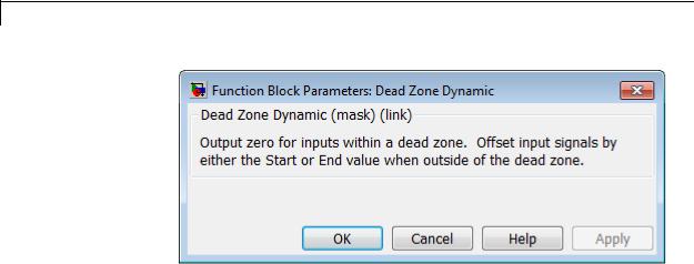
Dead Zone Dynamic
Parameters and Dialog Box
Characteristics
Direct Feedthrough |
Yes |
Scalar Expansion |
Yes |
|
|
See Also |
Dead Zone |
2-282
Decrement Real World
Purpose |
Decrease real world value of signal by one |
Library |
Additional Math & Discrete / Additional Math: Increment - Decrement |
Description |
The Decrement Real World block decreases the real world value of the |
|
signal by one. Overflows always wrap. |
Data Type The Decrement Real World block accepts signals of the following data
Support types:
•Floating point
•Built-in integer
•Fixed point
For more information, see “Data Types Supported by Simulink” in the
Simulink documentation.
Parameters and Dialog Box
2-283

Decrement Real World
Characteristics |
|
Direct Feedthrough |
|
Yes |
|
|
Scalar Expansion |
|
No |
|
|
Multidimensionalized |
|
No |
|
|
Zero-Crossing Detection |
|
No |
See Also |
|
Decrement Stored Integer, Decrement Time To Zero, Decrement To |
||
|
|
Zero, Increment Real World |
|
|
2-284
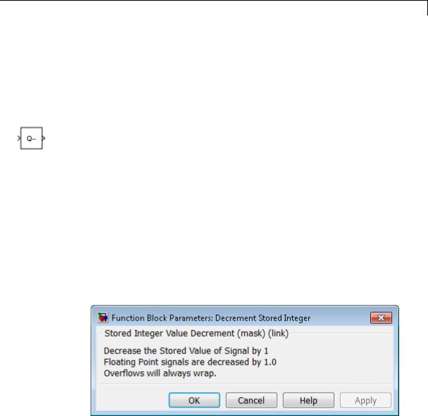
Decrement Stored Integer
Purpose |
Decrease stored integer value of signal by one |
Library |
Additional Math & Discrete / Additional Math: Increment - Decrement |
Description |
The Decrement Stored Integer block decreases the stored integer value |
|
of a signal by one. |
|
Floating-point signals also decrease by one, and overflows always wrap. |
Data Type |
The Decrement Stored Integer block accepts signals of the following |
Support |
data types: |
|
• Floating point |
|
• Built-in integer |
|
• Fixed point |
|
For more information, see “Data Types Supported by Simulink” in the |
|
Simulink documentation. |
Parameters and Dialog Box
2-285

Decrement Stored Integer
Characteristics |
|
Direct Feedthrough |
Yes |
|
|
Scalar Expansion |
No |
|
|
Multidimensionalized |
No |
|
|
Zero-Crossing Detection |
No |
See Also |
|
Decrement Real World, Decrement Time To Zero, Decrement To Zero, |
|
|
|
Increment Stored Integer |
|
2-286

Decrement Time To Zero
Purpose |
Decrease real-world value of signal by sample time, but only to zero |
Library |
Additional Math & Discrete / Additional Math: Increment - Decrement |
Description |
|
Data Type
Support
The Decrement Time To Zero block decreases the real-world value of the signal by the sample time, Ts. The output never goes below zero. This block works only with fixed sample rates and does not work inside a triggered subsystem.
The Decrement Time To Zero block accepts signals of the following data types:
•Floating point
•Built-in integer
•Fixed point
For more information, see “Data Types Supported by Simulink” in the Simulink documentation.
2-287
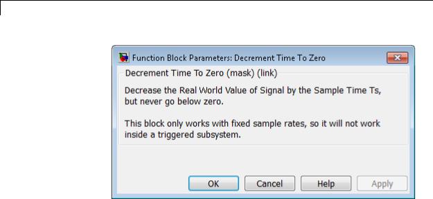
Decrement Time To Zero
Parameters and Dialog Box
Characteristics
Direct Feedthrough |
Yes |
Scalar Expansion |
No |
Multidimensionalized |
No |
Zero-Crossing Detection |
No |
|
|
See Also |
Decrement Real World, Decrement Stored Integer, Decrement To Zero |
2-288

Decrement To Zero
Purpose |
Decrease real-world value of signal by one, but only to zero |
Library |
Additional Math & Discrete / Additional Math: Increment - Decrement |
Description |
|
Data Type
Support
The Decrement To Zero block decreases the real-world value of the signal by one. The output never goes below zero.
The Decrement To Zero block accepts signals of the following data types:
•Floating point
•Built-in integer
•Fixed point
For more information, see “Data Types Supported by Simulink” in the Simulink documentation.
2-289

Decrement To Zero
Parameters and Dialog Box
Characteristics
Direct Feedthrough |
Yes |
Scalar Expansion |
No |
Multidimensionalized |
No |
Zero-Crossing Detection |
No |
|
|
See Also |
Decrement Real World, Decrement Stored Integer, Decrement Time |
|
To Zero |
2-290

Delay
Purpose |
Delay input signal by fixed or variable sample periods |
Library Discrete
Description Supported Block Operations
The Delay block supports:
•Variable delay length
•Specification of the initial condition from an input port
•Resetting the state to the initial condition with an external reset signal
•State storage
•Using a circular buffer instead of an array buffer for state storage
The Delay block delays an input u according to the Delay length parameter, which you specify on the dialog box, or a delay length that a signal supplies to the d input port. The initial block output depends on the Initial condition parameter, which you specify on the dialog box, or an initial condition that a signal supplies to the x0 input port. Whether or not the block output resets to the initial condition depends on the External reset parameter, which you specify on the dialog box.
The following dimensional requirements apply:
•Delay length and External reset must be scalar.
•Initial condition can be scalar or nonscalar.
•For frame-based processing, signal dimensions of the data input port u cannot be larger than two.
2-291

Delay
Block Icon Appearance
The icon changes depending on the number of block inputs.
|
Icon |
|
Number of Inputs |
|
|
|
|
One: |
|
|
|
|
• Input signal to delay, u |
|
|
|
|
|
|
Two:
•Input signal to delay, u
•Delay length, d
Three:
•Input signal to delay, u
•Delay length, d
•External reset
Four:
•Input signal to delay, u
•Delay length, d
•External reset
•Initial condition, x0
2-292
Delay
Data Type
Support
The block supports input signals of the following data types:
|
Input Signal |
Supported Data Types |
|
|
u |
• Floating point |
|
|
|
• Built-in integer |
|
|
|
• Fixed point |
|
|
|
• Boolean |
|
|
|
• Enumerated |
|
|
d |
• Floating point |
|
|
|
• Fixed-point integer |
|
|
x0 |
• Floating point |
|
|
|
• Built-in integer |
|
|
|
• Fixed point |
|
|
|
• Boolean |
|
|
|
• Enumerated |
|
|
|
|
|
When u is Boolean, x0 must be Boolean. When u uses an enumerated type, x0 must use the same enumerated type. Otherwise, x0 can use a floating-point, built-in integer, or fixed-point data type that fits in the data type of u. For example, when u uses int32, x0 can use int8 but not double.
The data type of the output signal is the same as the input signal u.
When you specify Delay length and Initial condition on the dialog box, you can use the following data types for those parameters:
2-293

Delay
|
Parameter |
Supported Data Types |
|
|
Delay length |
• Floating point |
|
|
|
• Fixed-point integer |
|
|
Initial condition |
• Floating point |
|
|
|
• Built-in integer |
|
|
|
• Fixed point |
|
|
|
• Boolean |
|
|
|
• Enumerated |
|
|
|
|
|
For more information, see “Data Types Supported by Simulink” in the Simulink documentation.
2-294

Delay
Parameters The Main pane of the Delay block dialog box appears as follows:
and Dialog Box
Delay length
Specify whether to enter the delay length directly on the dialog box (fixed delay) or to inherit the delay from an input port (variable delay).
•If you set Source to Dialog, enter the delay length in the edit field under Value.
2-295

Delay
•If you set Source to Input port, verify that an upstream signal supplies a delay length for the d input port. You can also specify an Upper limit for the delay length.
The scalar delay length (from the dialog parameter or an input port) must be a real, positive integer.
Initial condition
Specify whether to enter the initial condition directly on the dialog box or to inherit the initial condition from an input port.
•If you set Source to Dialog, enter the initial condition in the edit field under Value.
•If you set Source to Input port, verify that an upstream signal supplies an initial condition for the x0 input port.
Simulink converts offline the data type of Initial condition to the data type of the input signal u using a round-to-nearest operation and saturation.
Note When State name must resolve to Simulink signal object is selected on the State Attributes pane, the block copies the initial value of the signal object to the Initial condition parameter. However, when the source for Initial condition is Input port, the block ignores the initial value of the signal object.
External reset
Specify the trigger event to use to reset the states to the initial conditions.
|
Reset Mode |
Behavior |
|
|
None |
No reset. |
|
|
Rising |
Reset on a rising edge. |
|
|
Falling |
Reset on a falling edge. |
|
|
|
|
|
2-296

Delay
|
Reset Mode |
Behavior |
|
|
Either |
Reset on either a rising or |
|
|
|
falling edge. |
|
|
Level |
Reset in either of these cases: |
|
|
|
• when there is a nonzero at |
|
|
|
the current time step |
|
|
|
• when the time step value |
|
|
|
changes from nonzero at the |
|
|
|
previous time step to zero at |
|
|
|
the current time step |
|
|
Level hold |
Reset when nonzero at the |
|
|
|
current time step. |
|
The reset signal must be scalar.
Input processing
Specify whether the block performs sampleor frame-based processing. You can select one of the following options:
•Elements as channels (sample based) — Treat each element of the input as a separate channel (sample-based processing).
•Columns as channels (frame based) — Treat each column of the input as a separate channel (frame-based processing).
Note Frame-based processing requires a DSP System Toolbox license.
For more information, see “Sampleand Frame-Based Concepts” in the DSP System Toolbox documentation.
•Inherited — Inherit the processing mode from the input signal and delay the input accordingly. You can identify whether the
2-297

Delay
input signal is sample or frame based by looking at the signal line. Simulink represents sample-based signals with a single line and frame-based signals with a double line.
Note When you choose the Inherited option for the Input processing parameter, and the input signal is frame-based, Simulink® will generate a warning or error in future releases.
Use Input processing to specify whether the block performs sampleor frame-based processing. The block accepts frame-based signals for the input u. All other input signals must be sample based.
|
Input Signal u |
Input Processing |
Block Works? |
|
|
|
Mode |
|
|
|
Sample based |
Sample based |
Yes |
|
|
Frame based |
|
No, produces an |
|
|
|
|
error |
|
|
Sample based |
Frame based |
Yes |
|
|
Frame based |
|
Yes |
|
|
Sample based |
Inherited |
Yes |
|
|
Frame based |
|
Yes |
|
|
|
|
|
|
For more information about these two processing modes, see “Sampleand Frame-Based Concepts” in the DSP System Toolbox documentation.
Use circular buffer for state
Select to use a circular buffer for storing the state in simulation and code generation. Otherwise, an array buffer stores the state.
2-298

Delay
Using a circular buffer can improve execution speed when the delay length is large. For an array buffer, the number of copy operations increases as the delay length goes up. For a circular buffer, the number of copy operations is constant for increasing delay length.
If one of the following conditions is true, an array buffer always stores the state because a circular buffer does not improve execution speed:
•For sample-based signals, the delay length is 1.
•For frame-based signals, the delay length is no larger than the frame size.
Prevent direct feedthrough by increasing delay length to lower limit
Select to increase the delay length from zero to the lower limit for the Input processing mode:
•For sample-based signals, increase the minimum delay length to 1.
•For frame-based signals, increase the minimum delay length to the frame length.
Selecting this check box prevents direct feedthrough from the input port, u, to the output port. However, this check box cannot prevent direct feedthrough from the initial condition port, x0, to the output port.
This check box is available when you set Delay length: Source to Input port.
Remove protection against out-of-range delay length in generated code
Select to remove code that checks for out-of-range delay length.
2-299

Delay
|
Check Box |
Result |
When to Use |
|
|
Selected |
Generated code |
For code efficiency |
|
|
|
does not include |
|
|
|
|
conditional |
|
|
|
|
statements to check |
|
|
|
|
for out-of-range |
|
|
|
|
delay length. |
|
|
|
Cleared |
Generated code |
For safety-critical |
|
|
|
includes conditional |
applications |
|
|
|
statements to check |
|
|
|
|
for out-of-range |
|
|
|
|
delay length. |
|
|
This check box is available when you set Delay length: Source to Input port.
Diagnostic for out-of-range delay length
Specify whether to produce a warning or error when the input d is less than the lower limit or greater than the Delay length: Upper limit. The lower limit depends on the setting for Prevent direct feedthrough by increasing delay length to lower limit.
•If the check box is cleared, the lower limit is zero.
•If the check box is selected, the lower limit is 1 for sample-based signals and frame length for frame-based signals.
Options for the diagnostic include:
•None — No warning or error appears.
•Warning — Display a warning in the MATLAB Command Window and continue the simulation.
•Error — Stop the simulation and display an error in the Simulation Diagnostics Viewer.
2-300

Delay
This parameter is available when you set Delay length: Source to Input port.
Sample time (-1 for inherited)
Specify the time interval between samples. To inherit the sample time, set this parameter to -1. This block supports discrete sample time, but not continuous sample time.
As described in “Specify Sample Time”, you can specify a discrete sample time as [Tsampling, Toffset], where Tsampling is the sampling period and Toffset is the initial time offset. If Tstart is the simulation start time and n is the delay length, the Delay block output is as follows.
|
Simulation Time Range |
Block |
|
|
|
Output |
|
|
(Tstart) to (Tstart + Toffset) |
Zero |
|
|
(Tstart + Toffset) to (Tstart + Toffset + |
Initial |
|
|
n * Tsampling) |
condition |
|
|
After (Tstart + Toffset + n * Tsampling) |
Input |
|
|
|
signal |
|
If the Delay block inherits or specifies a nonzero value for Toffset, the Delay block outputs zero at Tstart. Otherwise, the Delay block outputs the initial condition at Tstart.
The State Attributes pane of the Delay block dialog box appears as follows:
2-301

Delay
State name
Use this parameter to assign a unique name to the block state. The default is ' '. When this field is blank, no name is assigned. When using this parameter, remember these considerations:
•A valid identifier starts with an alphabetic or underscore character, followed by alphanumeric or underscore characters.
•The state name applies only to the selected block.
2-302
Delay
This parameter enables State name must resolve to Simulink signal object when you click Apply.
For more information, see “States” in the Simulink Coder documentation.
State name must resolve to Simulink signal object
Select this check box to require that the state name resolve to a Simulink signal object. This check box is cleared by default.
State name enables this parameter.
Selecting this check box disables Code generation storage class.
Package
Select a package that defines the custom storage class you want to apply. If you have defined any packages of your own, click Refresh. This action adds all user-defined packages on your search path to the package list.
Code generation storage class
From the list, select a state storage class.
Auto
Auto is the storage class to use for states that do not need to interface to external code.
ExportedGlobal
The state is stored in a global variable.
ImportedExtern
model_private.h declares the state as an extern variable.
ImportedExternPointer
model_private.h declares the state as an extern pointer.
State name enables this parameter.
2-303

Delay
Variable-Size
Support
Setting this parameter to ExportedGlobal, ImportedExtern, or ImportedExternPointer enables Code generation storage type qualifier.
Code generation storage type qualifier
Specify a Simulink Coder storage type qualifier. The default is ' '. When this field is blank, no qualifier is assigned.
The Simulink Coder product does not check this string for errors. Thus, whatever value you enter appears automatically in the variable declaration.
Setting Code generation storage class to ExportedGlobal,
ImportedExtern, or ImportedExternPointer enables this parameter.
The Delay block provides the following support for variable-size signals:
•The data input port u accepts variable-size signals. The other input ports do not accept variable-size signals.
•The output port has the same signal dimensions as the data input port u for variable-size inputs.
The rules that apply to variable-size signals depend on the input processing mode of the Delay block.
|
Input Processing |
Rules for Variable-Size Signal Support |
|
|
Mode |
|
|
|
Elements as |
• The signal dimensions change only during |
|
|
channels (sample |
state reset when the block is enabled. |
|
|
based) |
• The initial condition must be scalar. |
|
|
|
|
|
|
Columns as |
• No support |
|
|
channels (frame |
|
|
|
based) |
|
|
|
|
|
|
2-304

Delay
|
Input Processing |
Rules for Variable-Size Signal Support |
|
|
Mode |
|
|
|
Inherited |
• The signal dimensions change only during |
|
|
(where input is |
state reset when the block is enabled. |
|
|
a sample-based |
• The initial condition must be scalar. |
|
|
signal) |
|
|
|
|
|
|
|
Inherited |
• The channel size changes only during state |
|
|
(where input is a |
reset when the block is enabled. |
|
|
frame-based signal) |
• The initial condition must be scalar. |
|
|
|
• The frame size must be constant. |
|
|
|
|
|
Bus |
The Delay block provides the following support for bus signals: |
Support |
• The data input port u accepts virtual and nonvirtual bus signals. The |
|
|
|
other input ports do not accept bus signals. |
|
• The output port has the same bus type as the data input port u for |
|
bus inputs. |
|
• Buses work with: |
|
- Sample-based and frame-based processing |
|
- Fixed and variable delay length |
|
- Array and circular buffers |
|
To use a bus signal as the input to a Delay block, you must specify the |
|
initial condition on the dialog box. In other words, the initial condition |
|
cannot come from the input port x0. Support for virtual and nonvirtual |
|
buses depends on the initial condition that you specify and whether the |
|
State name parameter is empty or not. |
2-305

Delay
|
Initial Condition |
State Name |
|
|
|
|
Empty |
Not Empty |
|
|
Zero |
Virtual and |
Nonvirtual bus |
|
|
|
nonvirtual bus |
support only |
|
|
|
support |
|
|
|
Nonzero scalar |
Virtual and |
No bus support |
|
|
|
nonvirtual bus |
|
|
|
|
support |
|
|
|
Nonscalar |
No bus support |
No bus support |
|
|
Structure |
Virtual and |
Nonvirtual bus |
|
|
|
nonvirtual bus |
support only |
|
|
|
support |
|
|
|
Partial structure |
Virtual and |
Nonvirtual bus |
|
|
|
nonvirtual bus |
support only |
|
|
|
support |
|
|
Examples Variable-Size Signals for Sample-Based Processing
This model shows how the Delay block supports variable-size signals for sample-based processing.
2-306

Delay
The Switch block controls whether the input signal to the enabled subsystem is a 3-by-3 or 3-by-2 matrix. The Delay block appears inside the enabled subsystem.
The model follows the rules for variable-size signals when the Delay block uses sample-based processing.
2-307

Delay
|
Rule |
How the Model Follows the Rule |
|
|
The signal dimensions |
The Enable block sets Propagate |
|
|
change only during state |
sizes of variable-size signals to |
|
|
reset when the block is |
Only when enabling. |
|
|
enabled. |
|
|
|
The initial condition must be |
The Delay block sets Initial |
|
|
scalar. |
condition to 0.0, a scalar value. |
|
Bus Signals for Frame-Based Processing
This model shows how the Delay block supports bus signals for frame-based processing.
Each Constant block supplies an input signal to the Bus Creator block, which outputs a two-dimensional bus signal. After the Delay block delays the bus signal by three sample periods, the Bus Selector block separates the bus back into the two original signals.
The model follows the rules for bus signals when the Delay block uses frame-based processing.
2-308

Delay
Characteristics
See Also
|
Rule |
How the Model Follows the Rule |
|
|
|
For the initial condition, set |
The Delay block sets Initial |
|
|
|
the value on the dialog box. |
condition to 0, a scalar value. |
|
|
|
For frame-based processing, |
The bus input to the Delay block has |
|
|
|
signal dimensions of the data |
two dimensions. |
|
|
|
input port u cannot be larger |
|
|
|
|
than two. (This rule applies |
|
|
|
|
to all inputs for the port u, |
|
|
|
|
not just bus signals.) |
|
|
|
|
|
|
|
|
|
Direct Feedthrough |
|
Yes, when you clear Prevent |
|
|
|
|
direct feedthrough by |
|
|
|
|
increasing delay length |
|
|
|
|
to lower limit |
|
|
Sample Time |
|
Specified in the Sample time |
|
|
|
|
parameter |
|
|
Scalar Expansion |
|
Yes, of the input u when Initial |
|
|
|
|
condition is nonscalar and |
|
|
|
|
sample-based processing applies |
|
|
Dimensionalized |
|
Yes |
|
|
Multidimensionalized |
|
Yes |
|
|
Zero-Crossing Detection |
|
No |
|
|
• Resettable Delay |
|
|
|
|
• Variable Integer Delay |
|
|
|
2-309

Demux
Purpose |
Extract and output elements of vector signal |
Library |
Signal Routing |
Description |
The Demux block extracts the components of an input signal and |
|
outputs the components as separate signals. The output signals are |
|
ordered from top to bottom output port. See “How to Rotate a Block” |
|
for a description of the port order for various block orientations. To |
|
avoid adding clutter to a model, Simulink hides the name of a Demux |
|
block when you copy it from the Simulink library to a model. See “Mux |
|
Signals” for information about creating and decomposing vectors. |
|
The Number of outputs parameter allows you to specify the number |
|
and, optionally, the dimensionality of each output port. If you do not |
|
specify the dimensionality of the outputs, the block determines the |
|
dimensionality of the outputs for you. |
|
The Demux block operates in either vector mode or bus selection mode, |
|
depending on whether you selected the Bus selection mode parameter. |
|
The two modes differ in the types of signals they accept. Vector mode |
|
accepts only a vector-like signal, that is, either a scalar (one-element |
|
array), vector (1-D array), or a column or row vector (one row or one |
|
column 2-D array). Bus selection mode accepts only a bus signal. |
|
|
|
Note MathWorks discourages enabling Bus selection mode and |
|
using a Demux block to extract elements of a bus signal. Muxes and |
|
buses should not be intermixed in new models. See “Avoid Mux/Bus |
|
Mixtures” for more information. |
|
The Number of outputs parameter determines the number and |
|
dimensionality of the block outputs, depending on the mode in which |
|
the block operates. |
|
Specifying the Number of Outputs in Vector Mode |
|
In vector mode, the value of the parameter can be a scalar specifying |
|
the number of outputs or a vector whose elements specify the widths of |
2-310

Demux
the block’s output ports. The block determines the size of its outputs from the size of the input signal and the value of the Number of outputs parameter.
The following table summarizes how the block determines the outputs for an input vector of width n.
|
Parameter Value |
Block outputs... |
Comments |
|
|
p = n |
p scalar signals |
For example, if the input is |
|
|
|
|
a three-element vector and |
|
|
|
|
you specify three outputs, |
|
|
|
|
the block outputs three |
|
|
|
|
scalar signals. |
|
|
p > n |
Error |
|
|
|
p < n |
p vector signals each having |
If the input is a six-element |
|
|
n mod p = 0 |
n/p elements |
vector and you specify three |
|
|
|
outputs, the block outputs |
|
|
|
|
|
|
|
|
|
|
three two-element vectors. |
|
|
p < n |
m vector signals each having |
If the input is a five-element |
|
|
n mod p = m |
(n/p)+1 elements and p-m |
vector and you specify |
|
|
signals having n/p elements |
three outputs, the block |
|
|
|
|
|
||
|
|
|
outputs two two-element |
|
|
|
|
vector signals and one scalar |
|
|
|
|
signal. |
|
|
[p1 p2 ... pm] |
m vector signals having |
If the input is a five-element |
|
|
p1+p2+...+pm=n |
widths p1, p2, ... pm |
vector and you specify [3, |
|
|
|
2] as the output, the block |
|
|
|
pi > 0 |
|
outputs three of the input |
|
|
|
|
elements on one port and the |
|
|
|
|
other two elements on the |
|
|
|
|
other port. |
|
2-311

Demux
|
Parameter Value |
|
Block outputs... |
Comments |
|
|
|
[p1 p2 ... |
pm] |
|
m vector signals |
If pi is greater than zero, |
|
|
p1+p2+...+pm=n |
|
|
the corresponding output |
|
|
|
|
|
has width pi. If pi is -1, the |
|
||
|
some or all |
|
|
|
width of the corresponding |
|
|
pi = -1 |
|
|
|
output is dynamically sized. |
|
|
|
|
|
|
|
|
|
[p1 p2 ... |
pm] |
|
Error |
|
|
|
p1+p2+...+pm!=n |
|
|
|
|
|
|
pi = > 0 |
|
|
|
|
|
|
|
|
Note that you can specify the number of outputs as fewer than the |
|
||
|
|
|
number of input elements, in which case the block distributes the |
|
||
|
|
|
elements as evenly as possible over the outputs as illustrated in the |
|
||
|
|
|
following example: |
|
|
|
You can use –1 in a vector expression to indicate that the block should dynamically size the corresponding port. For example, the expression [-1, 3 -1] causes the block to output three signals where the second signal always has three elements. The sizes of the first and third signals depend on the size of the input signal.
If a vector expression comprises positive values and –1 values, the block assigns as many elements as needed to the ports with positive values
2-312
Demux
and distributes the remain elements as evenly as possible over the ports with –1 values. For example, suppose that the block input is seven elements wide and you specify the output as [-1, 3 -1]. In this case, the block outputs two elements on the first port, three elements on the second, and two elements on the third.
Specifying the Number of Outputs in Bus Selection Mode
In bus selection mode, the value of the Number of outputs parameter can be a:
•Scalar specifying the number of output ports
The specified value must equal the number of input signals. For example, if the input bus comprises two signals and the value of this parameter is a scalar, the value must equal 2.
2-313

Demux
•Vector each of whose elements specifies the number of signals to output on the corresponding port
For example, if the input bus contains five signals, you can specify the output as [3, 2], in which case the block outputs three of the input signals on one port and the other two signals on a second port.
•Cell array each of whose elements is a cell array of vectors specifying the dimensions of the signals output by the corresponding port
The cell array format constrains the Demux block to accept only signals of specified dimensions. For example, the cell array {{[2 2], 3} {1}} tells the block to accept only a bus signal comprising a 2-by-2 matrix, a three-element vector, and a scalar signal. You can use the value –1 in a cell array expression to let the block determine the dimensionality of a particular output based on the input. For example, the following diagram uses the cell array expression {{ 1}, { 1, 1}} to specify the output of the leftmost Demux block.
2-314

Demux
Data Type
Support
In bus selection mode, if you specify the dimensionality of an output port (that is, specify any value other than –1), the corresponding input element must match the specified dimensionality.
Note MathWorks discourages enabling Bus selection mode and using a Demux block to extract elements of a bus signal. Muxes and buses should not be intermixed in new models. See “Avoid Mux/Bus Mixtures” for more information.
The Demux block accepts and outputs complex or real signals of any data type that Simulink supports, including fixed-point and enumerated data types.
For more information, see “Data Types Supported by Simulink” in the Simulink documentation.
2-315
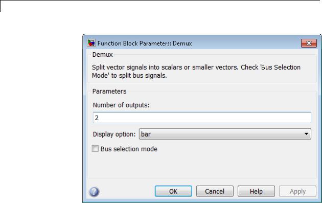
Demux
Parameters and Dialog Box
2-316

Demux
Number of outputs
Specify the number and dimensions of outputs.
Settings
Default: 2
This block interprets this parameter depending on the Bus selection mode parameter. See the block description for more information.
Command-Line Information
See “Block-Specific Parameters” on page 8-109 for the command-line information.
See Also
See the Demux block reference page for more information.
2-317

Demux
Display option
Select options to display the Demux block. The options are
Settings
Default: bar
bar
Display the icon as a solid bar of the block’s foreground color.
none
Display the icon as a box containing the block’s type name.
Command-Line Information
See “Block-Specific Parameters” on page 8-109 for the command-line information.
See Also
See the Demux block reference page for more information.
2-318

Demux
Bus selection mode
Enable bus selection mode.
Settings
Default: Off
 On
On
Enable bus selection mode.
 Off
Off
Disable bus selection mode.
Tips
MathWorks discourages enabling Bus selection mode and using a Demux block to extract elements of a bus signal. Muxes and buses
should not be intermixed in new models. See “Avoid Mux/Bus Mixtures” for more information.
Command-Line Information
See “Block-Specific Parameters” on page 8-109 for the command-line information.
Characteristics |
Virtual |
Yes |
|
|
For more information, see “Virtual |
|
|
Blocks” in the Simulink documentation. |
See Also |
Mux |
|
2-319


 to display the


 to display the


 to display the


 b
b 


 to display the
  to display the
 to display the
 to display the
  to display the
 to display the
 to display the
  to display the


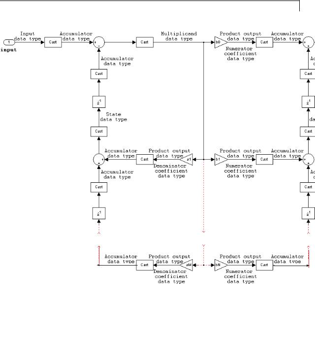


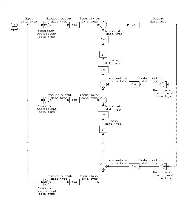


 b
b b
b


 to display the
  to display the
 to display the
  to display the
 to display the
  to display the


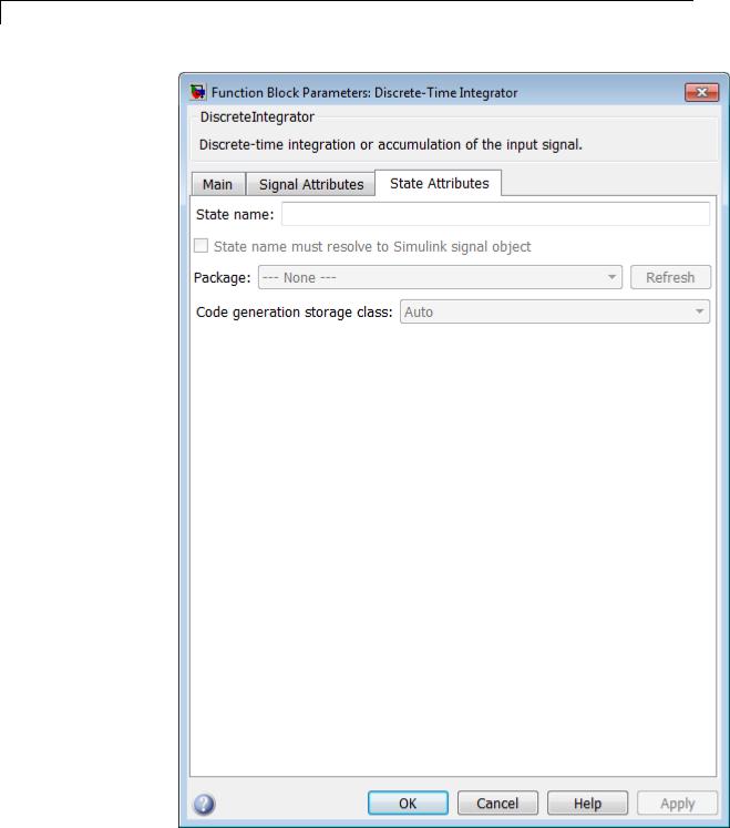


 On
On Off
Off


 On
On Off
Off
 On
On Off
Off
 On
On Off
Off
 On
On Off
Off

 On
On Off
Off


 On
On Off
Off


 b
b 
 b
b 


 to display the
  to display the
 to display the
 to display the
  to display the
 to display the
 to display the
  to display the


 to display the


