

- •Block Reference
- •Commonly Used
- •Continuous
- •Discontinuities
- •Discrete
- •Logic and Bit Operations
- •Lookup Tables
- •Math Operations
- •Model Verification
- •Model-Wide Utilities
- •Ports & Subsystems
- •Signal Attributes
- •Signal Routing
- •Sinks
- •Sources
- •User-Defined Functions
- •Additional Math & Discrete
- •Additional Discrete
- •Additional Math: Increment — Decrement
- •Run on Target Hardware
- •Target for Use with Arduino Hardware
- •Target for Use with BeagleBoard Hardware
- •Target for Use with LEGO MINDSTORMS NXT Hardware
- •Blocks — Alphabetical List
- •Command-Line Information
- •Command-Line Information
- •Command-Line Information
- •Command-Line Information
- •Command-Line Information
- •Command-Line Information
- •Command-Line Information
- •Command-Line Information
- •Command-Line Information
- •Command-Line Information
- •Command-Line Information
- •Command-Line Information
- •Command-Line Information
- •Command-Line Information
- •Command-Line Information
- •Command-Line Information
- •Settings Pane
- •Measurements Pane
- •Signal Statistics Measurements
- •Settings Pane
- •Transitions Pane
- •Overshoots/Undershoots
- •Cycles
- •Settings Pane
- •Peaks Pane
- •Command-Line Information
- •Command-Line Information
- •Command-Line Information
- •Command-Line Information
- •Command-Line Information
- •Command-Line Information
- •Command-Line Information
- •Command-Line Information
- •Command-Line Information
- •Function Reference
- •Model Construction
- •Simulation
- •Linearization and Trimming
- •Data Type
- •Examples
- •Main Toolbar
- •Command-Line Alternative
- •Command-Line Alternative
- •Command-Line Alternative
- •Command-Line Alternative
- •Command-Line Alternative
- •Command-Line Alternative
- •Mask Icon Drawing Commands
- •Simulink Classes
- •Model Parameters
- •About Model Parameters
- •Examples of Setting Model Parameters
- •Common Block Parameters
- •About Common Block Parameters
- •Examples of Setting Block Parameters
- •Block-Specific Parameters
- •Mask Parameters
- •About Mask Parameters
- •Notes on Mask Parameter Storage
- •Simulink Identifier
- •Simulink Identifier
- •Model Advisor Checks
- •Simulink Checks
- •Simulink Check Overview
- •See Also
- •Identify unconnected lines, input ports, and output ports
- •Description
- •Results and Recommended Actions
- •Capabilities and Limitations
- •Tips
- •See Also
- •Check root model Inport block specifications
- •Description
- •Results and Recommended Actions
- •See Also
- •Check optimization settings
- •Description
- •Results and Recommended Actions
- •Tips
- •See Also
- •Description
- •Results and Recommended Actions
- •See Also
- •Check for implicit signal resolution
- •Description
- •Results and Recommended Actions
- •See Also
- •Check for optimal bus virtuality
- •Description
- •Results and Recommended Actions
- •Capabilities and Limitations
- •See Also
- •Description
- •Results and Recommended Actions
- •Capabilities and Limitations
- •See Also
- •Identify disabled library links
- •Description
- •Results and Recommended Actions
- •Capabilities and Limitations
- •Tips
- •See Also
- •Identify parameterized library links
- •Description
- •Results and Recommended Actions
- •Capabilities and Limitations
- •Tips
- •See Also
- •Identify unresolved library links
- •Description
- •Results and Recommended Actions
- •Capabilities and Limitations
- •See Also
- •Results and Recommended Actions
- •Capabilities and Limitations
- •See Also
- •Results and Recommended Actions
- •Capabilities and Limitations
- •See Also
- •Check usage of function-call connections
- •Description
- •Results and Recommended Actions
- •See Also
- •Check signal logging save format
- •Description
- •Results and Recommended Actions
- •See Also
- •Description
- •Results and Recommended Actions
- •See Also
- •Description
- •Results and Recommended Actions
- •Tips
- •See Also
- •Check data store block sample times for modeling errors
- •Description
- •Results and Recommended Actions
- •See Also
- •Check for potential ordering issues involving data store access
- •Description
- •Results and Recommended Actions
- •Tips
- •See Also
- •Check for partial structure parameter usage with bus signals
- •Description
- •Results and Recommended Actions
- •Tips
- •See Also
- •Check for calls to slDataTypeAndScale
- •Description
- •Results and Recommended Actions
- •Tips
- •See Also
- •Check for proper bus usage
- •Description
- •Results and Recommended Actions
- •Action Results
- •Tips
- •See Also
- •Description
- •Results and Recommended Actions
- •See Also
- •Description
- •Results and Recommended Actions
- •See Also
- •Check for proper Merge block usage
- •Description
- •Input Parameters
- •Results and Recommended Actions
- •See Also
- •Description
- •Results and Recommended Actions
- •Action Results
- •See Also
- •Check for non-continuous signals driving derivative ports
- •Description
- •Results and Recommended Actions
- •See Also
- •Runtime diagnostics for S-functions
- •Description
- •Results and Recommended Actions
- •See Also
- •Check file for foreign characters
- •Description
- •Results and Recommended Actions
- •Tips
- •See Also
- •Check model for known block upgrade issues
- •Description
- •Results and Recommended Actions
- •Action Results
- •See Also
- •Description
- •Results and Recommended Actions
- •Action Results
- •See Also
- •Check that the model is saved in SLX format
- •Description
- •Results and Recommended Actions
- •Tips
- •See Also
- •Check Model History properties
- •Description
- •Results and Recommended Actions
- •See Also
- •Analyze model hierarchy for upgrade issues
- •Description
- •Results and Recommended Actions
- •Tips
- •See Also
- •Description
- •Results and Recommended Actions
- •See Also
- •Simulink Performance Advisor Checks
- •Simulink Performance Advisor Check Overview
- •See Also
- •Baseline
- •See Also
- •Check Preupdate Items
- •See Also
- •Checks that need Update Diagram
- •See Also
- •Checks that require simulation to run
- •See Also
- •Check Accelerator Settings
- •See Also
- •Create Baseline
- •See Also
- •Identify resource intensive diagnostic settings
- •See Also
- •Check optimization settings
- •See Also
- •Identify inefficient lookup table blocks
- •See Also
- •Identify Interpreted MATLAB Function blocks
- •See Also
- •Check MATLAB Function block debug settings
- •See Also
- •Check Stateflow block debug settings
- •See Also
- •Identify simulation target settings
- •See Also
- •Check model reference rebuild setting
- •See Also
- •Check Model Reference parallel build
- •See Also
- •Check solver type selection
- •See Also
- •Select normal or accelerator simulation mode
- •See Also
- •Simulink Limits
- •Maximum Size Limits of Simulink Models
- •Index
- •Filter Structures and Filter Coefficients
- •Valid Initial States
- •Number of Delay Elements (Filter States)
- •Frame-Based Processing
- •Sample-Based Processing
- •Valid Initial States
- •Frame-Based Processing
- •Sample-Based Processing
- •Model Parameters in Alphabetical Order
- •Common Block Parameters
- •Continuous Library Block Parameters
- •Discontinuities Library Block Parameters
- •Discrete Library Block Parameters
- •Logic and Bit Operations Library Block Parameters
- •Lookup Tables Block Parameters
- •Math Operations Library Block Parameters
- •Model Verification Library Block Parameters
- •Model-Wide Utilities Library Block Parameters
- •Ports & Subsystems Library Block Parameters
- •Signal Attributes Library Block Parameters
- •Signal Routing Library Block Parameters
- •Sinks Library Block Parameters
- •Sources Library Block Parameters
- •User-Defined Functions Library Block Parameters
- •Additional Discrete Block Library Parameters
- •Additional Math: Increment - Decrement Block Parameters
- •Mask Parameters

Multiport Switch
Allow different data input sizes
Select this check box to allow input signals with different sizes.
Settings
Default: Off
 On
On
Allows input signals with different sizes, and propagate the input signal size to the output signal.
 Off
Off
Requires that input signals be the same size.
Command-Line Information
Parameter: AllowDiffInputSize
Type: string
Value: 'on' | 'off'
Default: 'off'
2-1042
Multiport Switch
Output minimum
Specify the minimum value that the block outputs.
Settings
Default: []
The default value is [] (unspecified).
Simulink uses this value to perform:
•Simulation range checking (see “Signal Ranges”)
•Automatic scaling of fixed-point data types
Tip
This number must be a finite real double scalar value.
Command-Line Information
See “Block-Specific Parameters” on page 8-109 for the command-line information.
2-1043

Multiport Switch
Output maximum
Specify the maximum value the block outputs.
Settings
Default: []
The default value is [] (unspecified).
Simulink uses this value to perform:
•Simulation range checking (see “Signal Ranges”)
•Automatic scaling of fixed-point data types
Tip
This number must be a finite real double scalar value.
Command-Line Information
See “Block-Specific Parameters” on page 8-109 for the command-line information.
2-1044

Multiport Switch
Output data type
Specify the output data type.
Settings
Default: Inherit: Inherit via internal rule
Inherit: Inherit via internal rule
Simulink chooses a combination of output scaling and data type that requires the smallest amount of memory consistent with accommodating the calculated output range and maintaining the output precision of the block and with the word size of the targeted hardware implementation specified for the model.
If you set the Device type parameter on the Hardware Implementation configuration parameters pane to ASIC/FPGA, Simulink chooses the output data type without regard to hardware constraints. Otherwise, Simulink chooses the smallest available hardware data type capable of meeting the range and precision constraints. For example, if the block multiplies an input of type int8 by a gain of int16 and you specify ASIC/FPGA as the targeted hardware type, the output data type is sfix24. If you select Unspecified (assume 32-bit Generic) for a generic 32-bit microprocessor as the target hardware, the output data type is int32. If the word lengths provided by the target microprocessor cannot accommodate the output range, Simulink displays an error message in the Simulation Diagnostics Viewer.
Inherit: Inherit via back propagation
Uses the data type of the driving block.
double
Specifies output data type double.
single
Specifies output data type single.
int8
Specifies output data type int8.
2-1045

Multiport Switch
uint8
Specifies output data type uint8.
int16
Specifies output data type int16.
uint16
Specifies output data type uint16.
int32
Specifies output data type int32.
uint32
Specifies output data type uint32.
fixdt(1,16,0)
Specifies output data type fixed point fixdt(1,16,0).
fixdt(1,16,2^0,0)
Specifies output data type fixed point fixdt(1,16,2^0,0).
<data type expression>
Uses a data type object, for example, Simulink.NumericType.
Command-Line Information
See “Block-Specific Parameters” on page 8-109 for the command-line information.
2-1046

Multiport Switch
Mode
Select the category of data to specify.
Settings
Default: Inherit
Inherit
Specifies inheritance rules for data types. Selecting Inherit enables a list of possible values:
•Inherit via internal rule (default)
•Inherit via back propagation
Built in
Specifies built-in data types. Selecting Built in enables a list of possible values:
•double (default)
•single
•int8
•uint8
•int16
•uint16
•int32
•uint32
Fixed point
Specifies fixed-point data types.
Expression
Specifies expressions that evaluate to data types. Selecting Expression enables you to enter an expression.
Dependency
Clicking the Show data type assistant button enables this parameter.
2-1047

Multiport Switch
Command-Line Information
See “Block-Specific Parameters” on page 8-109 for the command-line information.
See Also
See “Specify Data Types Using Data Type Assistant”.
2-1048

Multiport Switch
Data type override
Specify data type override mode for this signal.
Settings
Default: Inherit
Inherit
Inherits the data type override setting from its context, that is, from the block, Simulink.Signal object or Stateflow chart in Simulink that is using the signal.
Off
Ignores the data type override setting of its context and uses the fixed-point data type specified for the signal.
Tip
The ability to turn off data type override for an individual data type provides greater control over the data types in your model when you apply data type override. For example, you can use this option to ensure that data types meet the requirements of downstream blocks regardless of the data type override setting.
Dependency
This parameter appears only when the Mode is Built in or Fixed point.
2-1049

Multiport Switch
Signedness
Specify fixed-point data as signed or unsigned.
Settings
Default: Signed
Signed
Specifies the fixed-point data as signed.
Unsigned
Specifies the fixed-point data as unsigned.
Dependency
Selecting Mode > Fixed point enables this parameter.
Command-Line Information
See “Block-Specific Parameters” on page 8-109 for the command-line information.
See Also
See “Specifying a Fixed-Point Data Type”.
2-1050

Multiport Switch
Word length
Specify the bit size of the word that holds the quantized integer.
Settings
Default: 16
Minimum: 0
Maximum: 32
Large word sizes represent large values with greater precision than small word sizes.
Dependency
Selecting Mode > Fixed point enables this parameter.
Command-Line Information
See “Block-Specific Parameters” on page 8-109 for the command-line information.
See Also
See “Specifying a Fixed-Point Data Type”.
2-1051

Multiport Switch
Scaling
Specify the method for scaling your fixed-point data to avoid overflow conditions and minimize quantization errors.
Settings
Default: Best precision
Binary point
Specify binary point location.
Slope and bias
Enter slope and bias.
Best precision
Specify best-precision values.
Dependencies
Selecting Mode > Fixed point enables this parameter. Selecting Binary point enables:
•Fraction length
•Calculate Best-Precision Scaling
Selecting Slope and bias enables:
•Slope
•Bias
•Calculate Best-Precision Scaling
Command-Line Information
See “Block-Specific Parameters” on page 8-109 for the command-line information.
See Also
For more information, see “Specifying a Fixed-Point Data Type”.
2-1052
Multiport Switch
Fraction length
Specify fraction length for fixed-point data type.
Settings
Default: 0
Binary points can be positive or negative integers.
Dependency
Selecting Scaling > Binary point enables this parameter.
Command-Line Information
See “Block-Specific Parameters” on page 8-109 for the command-line information.
See Also
See “Specifying a Fixed-Point Data Type”.
2-1053

Multiport Switch
Slope
Specify slope for the fixed-point data type.
Settings
Default: 2^0
Specify any positive real number.
Dependency
Selecting Scaling > Slope and bias enables this parameter.
Command-Line Information
See “Block-Specific Parameters” on page 8-109 for the command-line information.
See Also
See “Specifying a Fixed-Point Data Type”.
2-1054

Multiport Switch
Bus
Support
Bias
Specify bias for the fixed-point data type.
Settings
Default: 0
Specify any real number.
Dependency
Selecting Scaling > Slope and bias enables this parameter.
Command-Line Information
See “Block-Specific Parameters” on page 8-109 for the command-line information.
See Also
See “Specifying a Fixed-Point Data Type”.
The Multiport Switch block is a bus-capable block. The data inputs can be virtual or nonvirtual bus signals subject to the following restrictions:
•All the buses must be equivalent (same hierarchy with identical names and attributes for all elements).
•All signals in a nonvirtual bus input to a Multiport Switch block must have the same sample time. This requirement holds even when the elements of the associated bus object specify inherited sample times.
You can use a Rate Transition block to change the sample time of an individual signal, or of all signals in a bus. See “About Composite Signals” and “Bus-Capable Blocks” for more information.
You can use an array of buses as an input signal to a Multiport Switch block. For details about defining and using an array of buses, see “Combine Buses into an Array of Buses”. When you use an array of buses with a Multiport Switch block, set Number of data ports to a value of 2 or greater.
2-1055
Multiport Switch
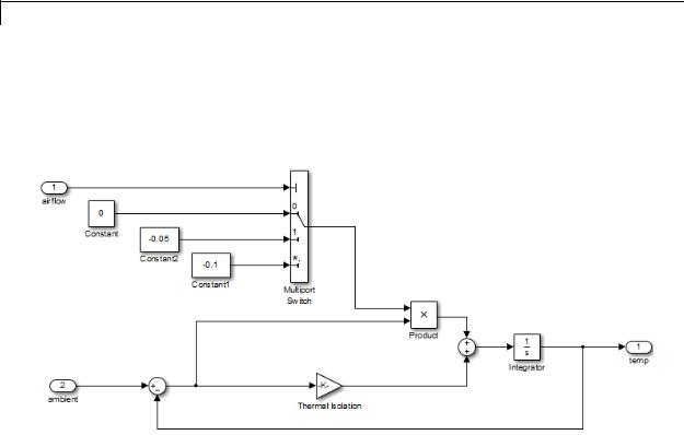
Examples Zero-Based Indexing for Data Ports
The sf_aircontrol model uses a Multiport Switch block in the Physical Plant subsystem. This block uses zero-based indexing for contiguous ordering of three data ports.
The indices are visible on the data port labels. You do not have to open the block dialog box to determine whether the data ports use zero-based or one-based indexing.
When you set Data port for default case to Last data port, the last data port includes a * on the label. The comma after the * indicates that the data port index has a value. This port corresponds to the default case, which applies when the control input does not match the data port indices 0, 1, or 2. In this case, the Multiport Switch block outputs a value of –0.1.
2-1056
Multiport Switch
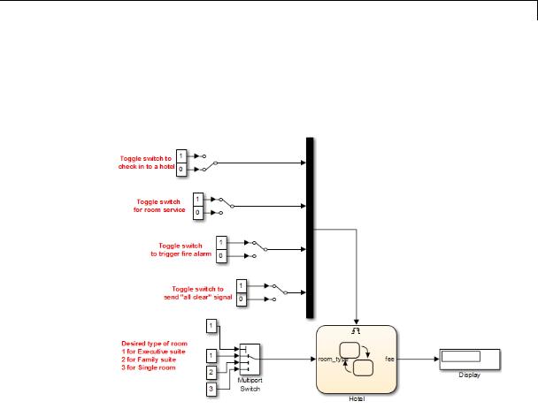
One-Based Indexing for Data Ports
The sf_semantics_hotel_checkin model uses a Multiport Switch block. This block uses one-based indexing for contiguous ordering of three data ports.
If you increase the size of the block icon, the indices are visible on the data port labels. You do not have to open the block dialog box to
determine whether the data ports use zero-based or one-based indexing.
2-1057
Multiport Switch
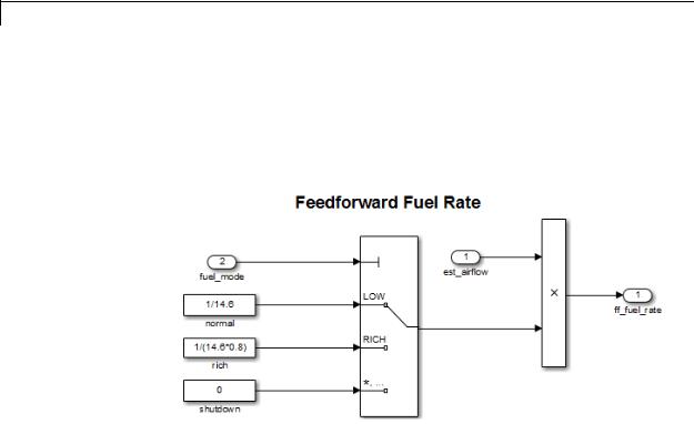
Enumerated Names for Data Port Indices
The sldemo_fuelsys model uses a Multiport Switch block in the fuel_rate_control/fuel_calc/feedforward_fuel_rate subsystem. This block uses the enumerated type sld_FuelModes to specify three data port indices: LOW, RICH, and DISABLED.
When you set Data port for default case to Last data port, the last data port includes a * on the label. The comma and ellipsis after the * indicate that the data port index has a value. This port corresponds to the default case, which applies when the control input does not match the data port indices LOW, RICH, or DISABLED. In this case, the Multiport Switch block outputs a value of 0.
2-1058
Multiport Switch
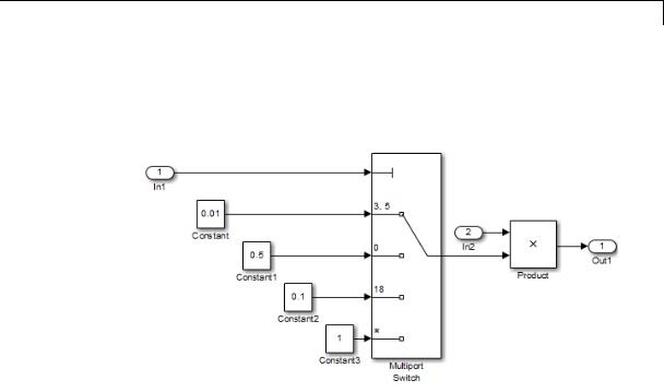
Noncontiguous Values for Data Port Indices
The following model uses a Multiport Switch block that specifies noncontiguous integer values for data ports.
The values of the indices are visible on the data port labels. You do not have to open the block dialog box to determine which value maps to each data port.
When you set Data port for default case to Additional data port, an extra port with a * label appears. This port corresponds to the default case, which applies when the control input does not match the data port indices 3, 5, 0, or 18. In this case, the Multiport Switch block outputs a value of 1.
2-1059

Multiport Switch
Behavior for an Index Vector Block
The following model uses two Index Vector blocks that specify zero-based and one-based indexing, respectively.
If the value of the control input is not an integer, the block truncates the value by rounding to floor. For more information, see “How the Block Interprets the Control Input” on page 2-1019.
Characteristics |
Bus-capable |
Yes, with restrictions |
|
Direct Feedthrough |
Yes |
|
Sample Time |
Specified in the Sample time |
|
|
parameter |
|
Scalar Expansion |
Yes |
|
Dimensionalized |
Yes |
|
|
|
2-1060

Multiport Switch
|
|
Multidimensionalized |
Yes |
|
|
Zero-Crossing Detection |
No |
See Also |
|
Switch |
|
2-1061

Mux
Purpose |
Combine several input signals into vector |
Library |
Signal Routing |
Description |
The Mux block combines its inputs into a single vector output. An input |
|
can be a scalar or vector signal. All inputs must be of the same data |
|
type and numeric type. The elements of the vector output signal take |
|
their order from the top to bottom, or left to right, input port signals. |
|
See “How to Rotate a Block” for a description of the port order for |
|
various block orientations. To avoid adding clutter to a model, Simulink |
|
hides the name of a Mux block when you copy it from the Simulink |
|
library to a model. See “Mux Signals” for information about creating |
|
and decomposing vectors. |
|
|
|
Note The Mux block allows you to connect signals of differing data and |
|
numeric types and matrix signals to its inputs. In this case, the Mux |
|
block acts like a Bus Creator block and outputs a bus signal rather |
|
than a vector. MathWorks discourages using Mux blocks to create bus |
|
signals, and might not support this practice in future releases. See |
|
“Avoid Mux/Bus Mixtures” for more information. |
|
Use the Number of inputs parameter to specify input signal names |
|
and sizes as well as the number of inputs. You can use one of the |
|
following formats: |
2-1062
Mux
|
Format |
Block Behavior |
|
|
Scalar |
Specifies the number of inputs to |
|
|
|
the Mux block. |
|
|
|
When you use this format, the |
|
|
|
block accepts scalar or vector |
|
|
|
signals of any size. Simulink |
|
|
|
assigns each input the name |
|
|
|
signalN, where N is the input |
|
|
|
port number. |
|
|
Vector |
The length of the vector specifies |
|
|
|
the number of inputs. Each |
|
|
|
element specifies the size of the |
|
|
|
corresponding input. |
|
|
|
A positive value specifies that |
|
|
|
the corresponding port can |
|
|
|
accept only vectors of that size. |
|
|
|
For example, [2 3] specifies |
|
|
|
two input ports of sizes 2 and |
|
|
|
3, respectively. If an input |
|
|
|
signal width does not match the |
|
|
|
expected width, an error message |
|
|
|
appears. A value of -1 specifies |
|
|
|
that the corresponding port can |
|
|
|
accept scalars or vectors of any |
|
|
|
size. |
|
2-1063

Mux
Data Type
Support
|
Format |
Block Behavior |
|
|
Cell array |
The length of the cell array |
|
|
|
specifies the number of inputs. |
|
|
|
The value of each cell specifies the |
|
|
|
size of the corresponding input. |
|
|
|
A scalar value N specifies a vector |
|
|
|
of size N. A value of -1 means |
|
|
|
that the corresponding port can |
|
|
|
accept scalar or vector signals of |
|
|
|
any size. |
|
|
Signal name list |
You can enter a list of signal |
|
|
|
names separated by commas. |
|
|
|
Simulink assigns each name |
|
|
|
to the corresponding port and |
|
|
|
signal. For example, if you enter |
|
|
|
position,velocity, the Mux |
|
|
|
block will have two inputs, named |
|
|
|
position and velocity. |
|
MathWorks encourages using Vector Concatenate blocks rather than Mux blocks to combine vectors. The primary exception is the creation of a vector of function calls, which requires a Mux block. In future releases, Mux blocks might have no unique capabilities and might be deprecated.
To create a composite signal, in which the constituent signals retain their identities and can have different data types, use a Bus Creator block rather than a Mux block. Although you can use a Mux block to create a composite signal, MathWorks discourages this practice. See “Avoid Mux/Bus Mixtures” for more information.
The Mux block accepts real or complex signals of any data type that Simulink supports, including fixed-point and enumerated data types.
For more information, see “Data Types Supported by Simulink” in the Simulink documentation.
2-1064
Mux
Parameters and Dialog Box
2-1065

Mux
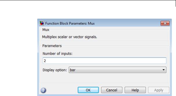
Number of inputs
Specify number and size of inputs.
Settings
Default: 2
You can enter a comma-separated list of signal names for this parameter field.
Command-Line Information
See “Block-Specific Parameters” on page 8-109 for the command-line information.
2-1066

Mux
Display option
Specify the appearance of the block in the model.
Settings
Default: bar
bar
Displays the block in a solid foreground color
none
Mux appears inside the block
signals
Displays signal names next to each port
Command-Line Information
See “Block-Specific Parameters” on page 8-109 for the command-line information.
2-1067
Mux
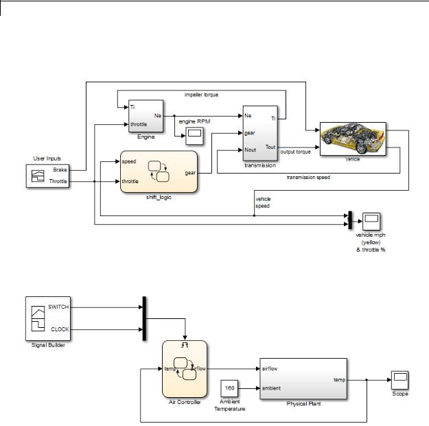
Examples The sf_car model uses a Mux block to combine two signals for input to a Scope block:
The sf_aircontrol model uses a Mux block to combine two signals for input to a Stateflow chart:
The following models also show how to use the Mux block:
2-1068

Mux
• sldemo_auto_climatecontrol
• sldemo_suspn
• sldemo_zeroxing
• penddemo
Characteristics |
Virtual |
Yes |
|
|
For more information, see “Virtual |
|
|
Blocks” in the Simulink documentation. |
See Also |
Demux |
|
2-1069

Outport
Purpose |
Create output port for subsystem or external output |
Library |
Ports & Subsystems, Sinks |
Description |
Outport blocks are the links from a system to a destination outside |
|
the system. |
|
Simulink software assigns Outport block port numbers according to |
|
these rules: |
•It automatically numbers the Outport blocks within a top-level system or subsystem sequentially, starting with 1.
•If you add an Outport block, it is assigned the next available number.
•If you delete an Outport block, other port numbers are automatically renumbered to ensure that the Outport blocks are in sequence and that no numbers are omitted.
Outport Blocks in a Subsystem
Outport blocks in a subsystem represent outputs from the subsystem. A signal arriving at an Outport block in a subsystem flows out of the associated output port on that Subsystem block. The Outport block associated with an output port on a Subsystem block is the block whose Port number parameter matches the relative position of the output port on the Subsystem block. For example, the Outport block whose Port number parameter is 1 sends its signal to the block connected to the topmost output port on the Subsystem block.
If you renumber the Port number of an Outport block, the block becomes connected to a different output port, although the block continues to send the signal to the same block outside the subsystem.
When you create a subsystem by selecting existing blocks, if more than one Outport block is included in the grouped blocks, Simulink software automatically renumbers the ports on the blocks.
The Outport block name appears in the Subsystem icon as a port label. To suppress display of the label, click the Outport block and select
Format > Hide Name.
2-1070

Outport
Outport Blocks in Conditionally Executed Contexts
When an Outport block is in a conditionally executed subsystem or a Model block, use one of the following approaches:
•Specify an initial output value for the Outport block.
•Use the value inherited from input signal of the Outport block.
Specifying Initial Conditions
To explicitly specify an initial output value:
1Select Dialog in the Source of initial output value drop-down list.
2Specify the Initial output parameter.
If you select Dialog, you can also specify what happens to the output when the subsystem is disabled, using the Output when disabled drop-down menu. Select either:
•reset – The output value is reset to the Initial output value when the subsystem is disabled.
•held – The output value remains at its most recent value when the subsystem is disabled.
Note If you are connecting the output of the conditionally executed subsystem to a Merge block, set Output when disabled to held to ensure consistent simulation results.
If you are using simplified initialization mode, you must select held when connecting a conditionally executed subsystem to a Merge block. However, you do not need to specify an Initial Condition (IC) for the Outport block of a conditionally executed subsystem that directly drives a Merge block. (This rule applies only when Outport and Merge blocks are in the same model.) For more information, see “Underspecified initialization detection”.
2-1071

Outport
Inheriting Initial Conditions
The initial output value of the outport block can be inherited from the following sources:
•Output port of another conditionally executed subsystem
•Merge block (with Initial output specified)
•Function-Call Model Reference block
•Constant block (simplified initialization mode only)
•IC block (simplified initialization mode only)
The procedure you use to inherit the initial conditions of the Outport block differs depending on whether you are using classic initialization mode or simplified initialization mode.
To inherit initial conditions in classic initialization mode:
1Select Dialog in the Source of initial output value drop-down list.
2Set the Initial output parameter to [] (empty matrix).
3Click OK.
Note For all other driving blocks, specify an explicit initial output value.
To inherit initial conditions in simplified initialization mode:
1 Select Input signal in the Source of initial output value drop-down list.
2Click OK.
The Initial output and Output when disabled parameters are disabled, and the values are both inherited from the input signal.
2-1072
Outport
For more information on classic and simplified initialization mode, see “Underspecified initialization detection”.
Outport Blocks in a Top-Level System
Outport blocks in a top-level system have two uses: to supply external outputs to the workspace, which you can do by using either the Model Configuration Parameters dialog box or the sim command, and to provide a means for analysis functions to obtain output from the system.
•To supply external outputs to the workspace, use the Configuration Parameters dialog box (see Exporting Output Data to the MATLAB Workspace) or the sim command (see sim). For example, if a system has more than one Outport block and the save format is array, the following command
[t,x,y] = sim(...);
writes y as a matrix, with each column containing data for a different Outport block. The column order matches the order of the port numbers for the Outport blocks.
If you specify more than one variable name after the second (state) argument, data from each Outport block is written to a different variable. For example, if the system has two Outport blocks, to save data from Outport block 1 to speed and the data from Outport block 2 to dist, you could specify this command:
[t,x,speed,dist] = sim(...);
•To provide a means for the linmod and trim analysis functions to obtain output from the system (see “Linearizing Models”)
Connecting Buses to Root Level Outports
A root level Outport of a model can accept a virtual bus only if all elements of the bus have the same data type. The Outport block automatically unifies the bus to a vector having the same number of elements as the bus, and outputs that vector.
2-1073

Outport
Data Type
Support
If you want a root level Outport of a model to accept a bus signal that contains mixed types, you must set the Outport block Data type parameter to use a bus object name for the Bus: <object name> or <data type expression> option, to define the type of bus that the Outport produces. If the bus signal is virtual, it will be converted to nonvirtual, as described in “Automatic Bus Conversion”. See “Bus Objects” more information.
The Outport block accepts real or complex signals of any data type that Simulink supports. An Outport block can also accept fixed-point and enumerated data types when the block is not a root-level output port. The complexity and data type of the block output are the same as those of its input. The Outport block also accepts a bus object as a data type.
Note If you specify a bus object as the data type for this block, do not set the minimum and maximum values for bus data on the
block. Simulink ignores these settings. Instead, set the minimum and maximum values for bus elements of the bus object specified as the data type. The values should be finite real double scalar.
For information on the Minimum and Maximum properties of a bus element, see Simulink.BusElement.
For more information, see “Data Types Supported by Simulink”.
The elements of a signal array connected to an Outport block can be of differing complexity and data types except in the following circumstance: If the output port is in a conditionally executed
subsystem and the initial output is specified, all elements of an input array must be of the same complexity and data types.
Typical Simulink data type conversion rules apply to an output port’s Initial output parameter. If the initial output value is in the range of the block’s output data type, Simulink software converts the initial output to the output data type. If the specified initial output is out
2-1074

Outport
of the range of the output data type, Simulink software halts the simulation and signals an error.
2-1075
Outport
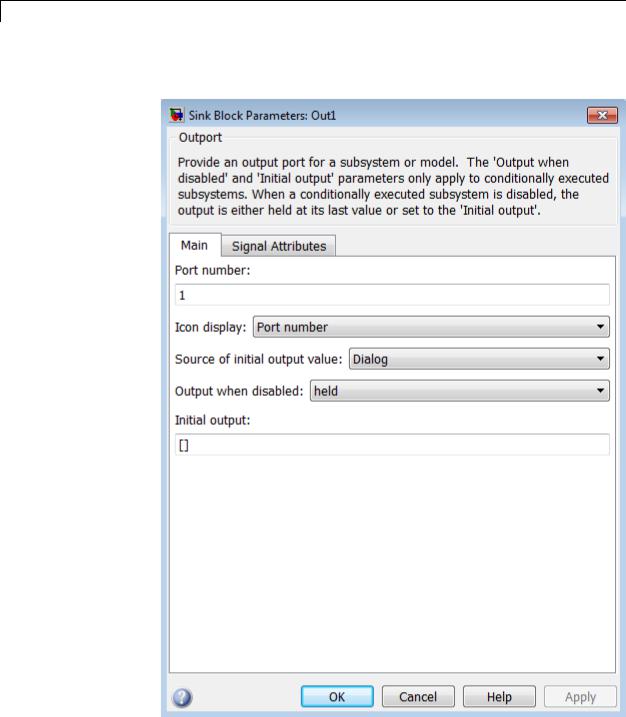
Parameters The Main pane of the Outport block dialog box appears as follows:
and Dialog Box
2-1076

Outport
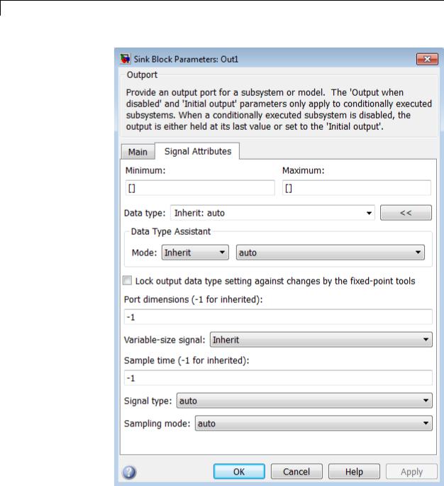
The Signal Attributes pane of the Outport block dialog box appears as follows:
2-1077
Outport
2-1078

Outport
•“Package” on page 2-1941
•“Icon display” on page 2-1081
•“Source of initial output value” on page 2-1082
•“Output when disabled” on page 2-1083
•“Initial output” on page 2-1084
•“Minimum” on page 2-1886
•“Maximum” on page 2-1887
•“Data type” on page 2-1086
•“Show data type assistant” on page 2-1665
•“Mode” on page 2-1089
•“Data type override” on page 2-1892
•“Signedness” on page 2-1893
•“Word length” on page 2-1896
•“Scaling” on page 2-1728
•“Fraction length” on page 2-1897
•“Slope” on page 2-1898
•“Bias” on page 2-1898
•“Lock output data type setting against changes by the fixed-point tools” on page 2-1713
•“Output as nonvirtual bus in parent model” on page 2-1097
•“Port dimensions (-1 for inherited)” on page 2-1099
•“Variable-size signal” on page 2-1100
•“Sample time (-1 for inherited)” on page 2-1938
•“Signal type” on page 2-1103
•“Sampling mode” on page 2-1104
2-1079

Outport
Port number
Specify the port number of the block.
Settings
Default: 1
This parameter controls the order in which the port that corresponds to the block appears on the parent subsystem or model block.
Command-Line Information
See “Block-Specific Parameters” on page 8-109 for the command-line information.
2-1080

Outport
Icon display
Specify the information to be displayed on the icon of this input port.
Settings
Default: Port number
Signal name
Display the name of the signal connected to this port (or signals if the input is a bus).
Port number
Display port number of this port.
Port number and signal name
Display both the port number and the names of the signals connected to this port.
Command-Line Information
See “Block-Specific Parameters” on page 8-109 for the command-line information.
2-1081

Outport
Source of initial output value
Select the source of the initial output value of the Outport block.
Settings
Default: Dialog
Dialog
The initial output value is specified by the Initial output parameter on the dialog.
Input signal
The initial output value is inherited from the input signal.
Tips
•If you are using classic initialization mode, you must select Dialog. Selecting Input signal will cause an error.
•If you are using classic initialization mode and want to inherit the initial output value, set this parameter to Dialog, and then specify [] (empty matrix) for the Initial output value. For more information, see Inheriting Initial Conditions on page 1072.
Dependencies
This parameter applies only if the Outport resides in an Enabled Subsystem.
Selecting Dialog enables the following parameters:
•Output when disabled
•Initial output
Command-Line Information
See “Block-Specific Parameters” on page 8-109 for the command-line information.
2-1082
Outport
Output when disabled
Specify what happens to the block output when the subsystem is disabled.
Settings
Default: held
held
Output is held when the subsystem is disabled.
reset
Output is reset when the subsystem is disabled.
Tips
•If you are connecting the output of a conditionally executed subsystem to a Merge block, set Output when disabled to held to ensure consistent simulation results.
•If you are using simplified initialization mode, you must select held when connecting a conditionally executed subsystem to a Merge block.
Dependencies
•Selecting Dialog in Source of initial output value enables this parameter.
•This parameter applies only if the Outport resides in an Enabled Subsystem.
Command-Line Information
See “Block-Specific Parameters” on page 8-109 for the command-line information.
2-1083

Outport
Initial output
For conditionally executed subsystems, specify the block output before the subsystem executes and while it is disabled.
Settings
Default: [ ]
Simulink software does not allow the initial output of this block to be inf or NaN.
Tips
•If you are using classic initialization mode, specify [] (empty matrix) to inherit the initial output value from the input signal. For more information, see Inheriting Initial Conditions on page 1072.
•You can also specify [] if you are using classic initialization mode, and your model does not depend on the initial output of the conditionally executed subsystem.
•If you are using simplified initialization mode, you cannot specify [], you must specify an explicit value. If you do not want to specify an initial output value for this block, set Source of initial output value to Input signal.
•For information about specifying an initial condition structure, see “Specify Initial Conditions for Bus Signals”
Dependencies
•Selecting Dialog in Source of initial output value enables this parameter.
•This parameter applies only if the Outport resides in an Enabled Subsystem.
Command-Line Information
See “Block-Specific Parameters” on page 8-109 for the command-line information.
2-1084

Outport
Minimum
Specify the minimum value that the block should output.
Settings
Default: [] (unspecified)
This number must be a finite real double scalar value.
Note If you specify a bus object as the data type for this block, do not set the minimum value for bus data on the block. Simulink ignores this setting. Instead, set the minimum values for bus elements of the bus object specified as the data type. For information on the Minimum property of a bus element, see Simulink.BusElement.
Simulink software uses this value to perform:
•Simulation range checking (see “Signal Ranges”)
•Automatic scaling of fixed-point data types
Command-Line Information
See “Block-Specific Parameters” on page 8-109 for the command-line information.
2-1085

Outport
Maximum
Specify the maximum value that the block should output.
Settings
Default: [] (unspecified)
This number must be a finite real double scalar value.
Note If you specify a bus object as the data type for this block, do not set the maximum value for bus data on the block. Simulink ignores this setting. Instead, set the maximum values for bus elements of the bus object specified as the data type. For information on the Maximum property of a bus element, see Simulink.BusElement.
Simulink software uses this value to perform:
•Simulation range checking (see “Signal Ranges”)
•Automatic scaling of fixed-point data types
Command-Line Information
See “Block-Specific Parameters” on page 8-109 for the command-line information.
Data type
Specify the output data type of the external input.
Settings
Default: Inherit: auto
Inherit: auto
A rule that inherits a data type
double
Data type is double.
single
Data type is single.
2-1086

Outport
int8
Data type is int8.
uint8
Data type is uint8.
int16
Data type is int16.
uint16
Data type is uint16.
int32
Data type is int32.
uint32
Data type is uint32.
boolean
Data type is boolean.
fixdt(1,16,0)
Data type is fixed point fixdt(1,16,0).
fixdt(1,16,2^0,0)
Data type is fixed point fixdt(1,16,2^0,0).
Enum: <class name>
Data type is enumerated, for example, Enum: BasicColors.
Bus: <object name>
Data type is a bus object.
<data type expression>
The name of a data type object, for example
Simulink.NumericType
Do not specify a bus object as the expression.
Command-Line Information
See “Block-Specific Parameters” on page 8-109 for the command-line information.
2-1087

Outport
Show data type assistant
Display the Data Type Assistant.
Settings
The Data Type Assistant helps you set the Output data type parameter.
For more information, see “Specify Block Output Data Types”.
Command-Line Information
See “Block-Specific Parameters” on page 8-109 for the command-line information.
2-1088

Outport
Mode
Select the category of data to specify.
Settings
Default: Inherit
Inherit
Inheritance rule for data types. Selecting Inherit enables a second menu/text box to the right.
Built in
Built-in data types. Selecting Built in enables a second menu/text box to the right. Select one of the following choices:
•double (default)
•single
•int8
•uint8
•int16
•uint16
•int32
•uint32
•boolean
Fixed point
Fixed-point data types.
Enumerated
Enumerated data types. Selecting Enumerated enables a second menu/text box to the right, where you can enter the class name.
Bus
Bus object. Selecting Bus enables a Bus object parameter to the right, where you enter the name of a bus object that you want to use to define the structure of the bus. If you need to create or
2-1089

Outport
change a bus object, click Edit to the right of the Bus object field to open the Simulink Bus Editor. For details about the Bus Editor, see “Manage Bus Objects with the Bus Editor”.
Expression
Expressions that evaluate to data types. Selecting Expression enables a second menu/text box to the right, where you can enter the expression.
Do not specify a bus object as the expression.
Dependency
Clicking the Show data type assistant button enables this parameter.
Command-Line Information
See “Block-Specific Parameters” on page 8-109 for the command-line information.
See Also
See “Specify Data Types Using Data Type Assistant”.
2-1090

Outport
Data type override
Specify data type override mode for this signal.
Settings
Default: Inherit
Inherit
Inherits the data type override setting from its context, that is, from the block, Simulink.Signal object or Stateflow chart in Simulink that is using the signal.
Off
Ignores the data type override setting of its context and uses the fixed-point data type specified for the signal.
Tip
The ability to turn off data type override for an individual data type provides greater control over the data types in your model when you apply data type override. For example, you can use this option to ensure that data types meet the requirements of downstream blocks regardless of the data type override setting.
Dependency
This parameter appears only when the Mode is Built in or Fixed point.
2-1091

Outport
Signedness
Specify whether you want the fixed-point data as signed or unsigned.
Settings
Default: Signed
Signed
Specify the fixed-point data as signed.
Unsigned
Specify the fixed-point data as unsigned.
Dependencies
Selecting Mode > Fixed point enables this parameter.
Command-Line Information
See “Block-Specific Parameters” on page 8-109 for the command-line information.
See Also
For more information, see “Specifying a Fixed-Point Data Type”.
2-1092
Outport
Word length
Specify the bit size of the word that holds the quantized integer.
Settings
Default: 16
Minimum: 0
Maximum: 32
Dependencies
Selecting Mode > Fixed point enables this parameter.
Command-Line Information
See “Block-Specific Parameters” on page 8-109 for the command-line information.
See Also
For more information, see “Specifying a Fixed-Point Data Type”.
2-1093

Outport
Scaling
Specify the method for scaling your fixed-point data to avoid overflow conditions and minimize quantization errors.
Settings
Default: Best precision
Binary point
Specify binary point location.
Slope and bias
Enter slope and bias.
Best precision
Specify best-precision values.
Dependencies
Selecting Mode > Fixed point enables this parameter. Selecting Binary point enables:
•Fraction length
•Calculate Best-Precision Scaling
Selecting Slope and bias enables:
•Slope
•Bias
•Calculate Best-Precision Scaling
Command-Line Information
See “Block-Specific Parameters” on page 8-109 for the command-line information.
See Also
For more information, see “Specifying a Fixed-Point Data Type”.
2-1094

Outport
Fraction length
Specify fraction length for fixed-point data type.
Settings
Default: 0
Binary points can be positive or negative integers.
Dependencies
Selecting Scaling > Binary point enables this parameter.
Command-Line Information
See “Block-Specific Parameters” on page 8-109 for the command-line information.
See Also
For more information, see “Specifying a Fixed-Point Data Type”.
2-1095

Outport
Slope
Specify slope for the fixed-point data type.
Settings
Default: 2^0
Specify any positive real number.
Dependencies
Selecting Scaling > Slope and bias enables this parameter.
Command-Line Information
See “Block-Specific Parameters” on page 8-109 for the command-line information.
See Also
For more information, see “Specifying a Fixed-Point Data Type”.
Bias
Specify bias for the fixed-point data type.
Settings
Default: 0
Specify any real number.
Dependencies
Selecting Scaling > Slope and bias enables this parameter.
Command-Line Information
See “Block-Specific Parameters” on page 8-109 for the command-line information.
See Also
For more information, see “Specifying a Fixed-Point Data Type”.
2-1096

Outport
Lock output data type setting against changes by the fixed-point tools
Select to lock the output data type setting of this block against changes by the Fixed-Point Tool and the Fixed-Point Advisor.
Settings
Default: Off
 On
On
Locks the output data type setting for this block.
 Off
Off
Allows the Fixed-Point Tool and the Fixed-Point Advisor to change the output data type setting for this block.
Command-Line Information
See “Block-Specific Parameters” on page 8-109 for the command-line information.
See Also
For more information, see “Use Lock Output Data Type Setting”.
Output as nonvirtual bus in parent model
Select this parameter if you want the bus emerging in the parent model to be nonvirtual. The bus that is input to the port can be virtual or nonvirtual, regardless of the setting of Output as nonvirtual bus
in parent model.
Settings
Default: Off
 On
On
Select this parameter if you want the bus emerging in the parent model to be nonvirtual.
 Off
Off
Clear this parameter if you want the bus emerging in the parent model to be virtual.
2-1097

Outport
Tips
All signals in a nonvirtual bus must have the same sample time, even if the elements of the associated bus object specify inherited sample times. Any bus operation that would result in a nonvirtual bus that violates this requirement generates an error. Therefore, if you select this option all signals in the bus must have the same sample time. You can use a Rate Transition block to change the sample time of an individual signal, or of all signals in a bus, to allow the signal or bus to be included in a nonvirtual bus.
Dependency
via bus object enables this parameter.
Command-Line Information
See “Block-Specific Parameters” on page 8-109 for the command-line information.
2-1098

Outport
Port dimensions (-1 for inherited)
Specify the dimensions that a signal must have in order to be connected to this Outport block.
Settings
Default: -1
Valid values are:
-1 |
A signal of any dimensions can be connected to this |
|
port. |
N |
The signal connected to this port must be a vector |
|
of size N. |
[R C] |
The signal connected to this port must be a matrix |
|
having R rows and C columns. |
Dependency
Clearing via bus object enables this parameter.
Command-Line Information
See “Block-Specific Parameters” on page 8-109 for the command-line information.
2-1099