

- •Block Reference
- •Commonly Used
- •Continuous
- •Discontinuities
- •Discrete
- •Logic and Bit Operations
- •Lookup Tables
- •Math Operations
- •Model Verification
- •Model-Wide Utilities
- •Ports & Subsystems
- •Signal Attributes
- •Signal Routing
- •Sinks
- •Sources
- •User-Defined Functions
- •Additional Math & Discrete
- •Additional Discrete
- •Additional Math: Increment — Decrement
- •Run on Target Hardware
- •Target for Use with Arduino Hardware
- •Target for Use with BeagleBoard Hardware
- •Target for Use with LEGO MINDSTORMS NXT Hardware
- •Blocks — Alphabetical List
- •Command-Line Information
- •Command-Line Information
- •Command-Line Information
- •Command-Line Information
- •Command-Line Information
- •Command-Line Information
- •Command-Line Information
- •Command-Line Information
- •Command-Line Information
- •Command-Line Information
- •Command-Line Information
- •Command-Line Information
- •Command-Line Information
- •Command-Line Information
- •Command-Line Information
- •Command-Line Information
- •Settings Pane
- •Measurements Pane
- •Signal Statistics Measurements
- •Settings Pane
- •Transitions Pane
- •Overshoots/Undershoots
- •Cycles
- •Settings Pane
- •Peaks Pane
- •Command-Line Information
- •Command-Line Information
- •Command-Line Information
- •Command-Line Information
- •Command-Line Information
- •Command-Line Information
- •Command-Line Information
- •Command-Line Information
- •Command-Line Information
- •Function Reference
- •Model Construction
- •Simulation
- •Linearization and Trimming
- •Data Type
- •Examples
- •Main Toolbar
- •Command-Line Alternative
- •Command-Line Alternative
- •Command-Line Alternative
- •Command-Line Alternative
- •Command-Line Alternative
- •Command-Line Alternative
- •Mask Icon Drawing Commands
- •Simulink Classes
- •Model Parameters
- •About Model Parameters
- •Examples of Setting Model Parameters
- •Common Block Parameters
- •About Common Block Parameters
- •Examples of Setting Block Parameters
- •Block-Specific Parameters
- •Mask Parameters
- •About Mask Parameters
- •Notes on Mask Parameter Storage
- •Simulink Identifier
- •Simulink Identifier
- •Model Advisor Checks
- •Simulink Checks
- •Simulink Check Overview
- •See Also
- •Identify unconnected lines, input ports, and output ports
- •Description
- •Results and Recommended Actions
- •Capabilities and Limitations
- •Tips
- •See Also
- •Check root model Inport block specifications
- •Description
- •Results and Recommended Actions
- •See Also
- •Check optimization settings
- •Description
- •Results and Recommended Actions
- •Tips
- •See Also
- •Description
- •Results and Recommended Actions
- •See Also
- •Check for implicit signal resolution
- •Description
- •Results and Recommended Actions
- •See Also
- •Check for optimal bus virtuality
- •Description
- •Results and Recommended Actions
- •Capabilities and Limitations
- •See Also
- •Description
- •Results and Recommended Actions
- •Capabilities and Limitations
- •See Also
- •Identify disabled library links
- •Description
- •Results and Recommended Actions
- •Capabilities and Limitations
- •Tips
- •See Also
- •Identify parameterized library links
- •Description
- •Results and Recommended Actions
- •Capabilities and Limitations
- •Tips
- •See Also
- •Identify unresolved library links
- •Description
- •Results and Recommended Actions
- •Capabilities and Limitations
- •See Also
- •Results and Recommended Actions
- •Capabilities and Limitations
- •See Also
- •Results and Recommended Actions
- •Capabilities and Limitations
- •See Also
- •Check usage of function-call connections
- •Description
- •Results and Recommended Actions
- •See Also
- •Check signal logging save format
- •Description
- •Results and Recommended Actions
- •See Also
- •Description
- •Results and Recommended Actions
- •See Also
- •Description
- •Results and Recommended Actions
- •Tips
- •See Also
- •Check data store block sample times for modeling errors
- •Description
- •Results and Recommended Actions
- •See Also
- •Check for potential ordering issues involving data store access
- •Description
- •Results and Recommended Actions
- •Tips
- •See Also
- •Check for partial structure parameter usage with bus signals
- •Description
- •Results and Recommended Actions
- •Tips
- •See Also
- •Check for calls to slDataTypeAndScale
- •Description
- •Results and Recommended Actions
- •Tips
- •See Also
- •Check for proper bus usage
- •Description
- •Results and Recommended Actions
- •Action Results
- •Tips
- •See Also
- •Description
- •Results and Recommended Actions
- •See Also
- •Description
- •Results and Recommended Actions
- •See Also
- •Check for proper Merge block usage
- •Description
- •Input Parameters
- •Results and Recommended Actions
- •See Also
- •Description
- •Results and Recommended Actions
- •Action Results
- •See Also
- •Check for non-continuous signals driving derivative ports
- •Description
- •Results and Recommended Actions
- •See Also
- •Runtime diagnostics for S-functions
- •Description
- •Results and Recommended Actions
- •See Also
- •Check file for foreign characters
- •Description
- •Results and Recommended Actions
- •Tips
- •See Also
- •Check model for known block upgrade issues
- •Description
- •Results and Recommended Actions
- •Action Results
- •See Also
- •Description
- •Results and Recommended Actions
- •Action Results
- •See Also
- •Check that the model is saved in SLX format
- •Description
- •Results and Recommended Actions
- •Tips
- •See Also
- •Check Model History properties
- •Description
- •Results and Recommended Actions
- •See Also
- •Analyze model hierarchy for upgrade issues
- •Description
- •Results and Recommended Actions
- •Tips
- •See Also
- •Description
- •Results and Recommended Actions
- •See Also
- •Simulink Performance Advisor Checks
- •Simulink Performance Advisor Check Overview
- •See Also
- •Baseline
- •See Also
- •Check Preupdate Items
- •See Also
- •Checks that need Update Diagram
- •See Also
- •Checks that require simulation to run
- •See Also
- •Check Accelerator Settings
- •See Also
- •Create Baseline
- •See Also
- •Identify resource intensive diagnostic settings
- •See Also
- •Check optimization settings
- •See Also
- •Identify inefficient lookup table blocks
- •See Also
- •Identify Interpreted MATLAB Function blocks
- •See Also
- •Check MATLAB Function block debug settings
- •See Also
- •Check Stateflow block debug settings
- •See Also
- •Identify simulation target settings
- •See Also
- •Check model reference rebuild setting
- •See Also
- •Check Model Reference parallel build
- •See Also
- •Check solver type selection
- •See Also
- •Select normal or accelerator simulation mode
- •See Also
- •Simulink Limits
- •Maximum Size Limits of Simulink Models
- •Index
- •Filter Structures and Filter Coefficients
- •Valid Initial States
- •Number of Delay Elements (Filter States)
- •Frame-Based Processing
- •Sample-Based Processing
- •Valid Initial States
- •Frame-Based Processing
- •Sample-Based Processing
- •Model Parameters in Alphabetical Order
- •Common Block Parameters
- •Continuous Library Block Parameters
- •Discontinuities Library Block Parameters
- •Discrete Library Block Parameters
- •Logic and Bit Operations Library Block Parameters
- •Lookup Tables Block Parameters
- •Math Operations Library Block Parameters
- •Model Verification Library Block Parameters
- •Model-Wide Utilities Library Block Parameters
- •Ports & Subsystems Library Block Parameters
- •Signal Attributes Library Block Parameters
- •Signal Routing Library Block Parameters
- •Sinks Library Block Parameters
- •Sources Library Block Parameters
- •User-Defined Functions Library Block Parameters
- •Additional Discrete Block Library Parameters
- •Additional Math: Increment - Decrement Block Parameters
- •Mask Parameters

Outport
Variable-size signal
Specify the type of signals allowed out of this port.
Settings
Default: Inherit
Inherit
Allow variable-size and fixed-size signals.
No
Do not allow variable-size signals.
Yes
Allow only variable-size signals.
Dependencies
When the signal at this port is a variable-size signal, the Port dimensions parameter specifies the maximum dimensions of the signal.
Command-Line Information
Parameter: VarSizeSig
Type: string
Value: 'Inherit’| 'No' | 'Yes'
Default: 'Inherit'
2-1100

Outport
Sample time (-1 for inherited)
Enter the discrete interval between sample time hits or specify another appropriate sample time such as continuous or inherited.
Settings
Default: -1
By default, the block inherits its sample time based upon the context of the block within the model. To set a different sample time, enter a valid sample time based upon the table in “Types of Sample Time”.
See also “Specify Sample Time” in the online documentation for more information.
Command-Line Information
See “Block-Specific Parameters” on page 8-109 for the command-line information.
2-1101

Outport
2-1102
Outport
Signal type
Specify the numeric type of the signal output by this block.
Settings
Default: auto
auto
Output the numeric type of the signal that is connected to its input.
real
Output a real-valued signal. The signal connected to this block must be real. If it is not, Simulink software displays an error if you try to update the diagram or simulate the model that contains this block.
complex
Output a complex signal. The signal connected to this block must be complex. If it is not, Simulink software displays an error if you try to update the diagram or simulate the model that contains this block.
Command-Line Information
See “Block-Specific Parameters” on page 8-109 for the command-line information.
2-1103

Outport
Sampling mode
Specify the sampling mode (Sample based or Frame based) that the input signal must match.
Settings
Default: auto
auto
Accept any sampling mode.
Sample based
The output signal is sample-based.
Frame based
The output signal is frame-based.
Dependency
Frame-based processing requires a DSP System Toolbox license.
For more information, see “Sampleand Frame-Based Concepts” in the DSP System Toolbox documentation.
Command-Line Information
See “Block-Specific Parameters” on page 8-109 for the command-line information.
2-1104

Outport
Characteristics
See Also
Sample Time |
Inherited from the driving block |
Dimensionalized |
Yes |
|
|
Multidimensionalized |
Yes |
Virtual |
Yes, when the block resides in a |
|
subsystem block and not at the root |
|
level of a model |
|
For more information, see |
|
“Virtual Blocks” in the Simulink |
|
documentation. |
Zero-Crossing Detection |
No |
|
|
Inport
2-1105

Permute Dimensions
Purpose |
Rearrange dimensions of multidimensional array dimensions |
Library |
Math Operations |
Description |
The block reorders the elements of the input signal so that they are in |
|
the order you specify in the Order parameter. |
Data Type This block accepts signals of any data type that Simulink supports,
Support including fixed-point and enumerated data types. Output must be the same data type as the input.
You can use an array of buses as an input signal to a Permute Dimensions block. For details about defining and using an array of buses, see “Combine Buses into an Array of Buses”.
For more information, see “Data Types Supported by Simulink” in the Simulink documentation.
2-1106

Permute Dimensions
Parameters and Dialog Box
Order
Specify the permutation order to apply to the dimensions of the input signal. This parameter is a vector of elements, where the number of elements in the vector is the number of dimensions of the input signal.
Characteristics |
Direct Feedthrough |
Yes |
|
Sample Time |
Inherited from driving block |
|
Scalar Expansion |
No |
|
|
|
2-1107

Permute Dimensions
Dimensionalized |
Yes |
Multidimensionalized |
Yes |
Zero-Crossing Detection |
No |
|
|
See Also Math Function (transpose), permute (in the MATLAB reference documentation)
2-1108

PID Controller
Purpose |
Simulate continuousor discrete-time PID controllers |
Library |
Continuous, Discrete |
Description |
Implement a continuousor discrete-time controller (PID, PI, PD, |
|
P, or I) in your Simulink model. PID controller gains are tunable |
|
either manually or automatically. Automatic tuning requires Simulink |
|
Control Design™ software (PID Tuner or SISO Design Tool). |
|
The PID Controller block output is a weighted sum of the input |
|
signal, the integral of the input signal, and the derivative of the input |
|
signal. The weights are the proportional, integral, and derivative gain |
|
parameters. A first-order pole filters the derivative action. |
|
Configurable options in the PID Controller block include: |
|
• Controller type (PID, PI, PD, P, or I) |
|
• Controller form (Parallel or Ideal) |
|
• Time domain (continuous or discrete) |
|
• Initial conditions and reset trigger |
|
• Output saturation limits and built-in anti-windup mechanism |
|
• Signal tracking for bumpless control transfer and multiloop control |
|
In one common implementation, the PID Controller block operates in |
|
the feedforward path of the feedback loop: |
2-1109

PID Controller
Data Type
Support
The input of the block is typically an error signal, which is the difference between a reference signal and the system output. For a two-input block that permits setpoint weighting, see the PID Controller (2 DOF) block reference page.
You can generate code to implement your controller using any Simulink data type, including fixed-point data types. (Code generation requires Simulink Coder software; fixed-point implementation requires the Fixed-Point Toolbox product.)
For examples illustrating some applications of the PID Controller block, see the following Simulink examples:
•Anti-Windup Control Using a PID Controller
•Bumpless Control Transfer Between Manual and PID Control
The PID Controller block accepts real signals of any numeric data type that Simulink software supports, including fixed-point data types. See “Data Types Supported by Simulink” in the Simulink documentation for more information.
|
Parameters |
The following table summarizes the PID Controller block parameters, |
|
|
|
|
accessible on the block parameter dialog box. |
|
|
|
|
|
|
|
|
Task |
|
Parameters |
|
|
Choose controller form and type. |
• Controller Form in Main tab |
|
|
|
|
|
• Controller |
|
|
Choose discrete or continuous time. |
• Time-domain |
|
|
|
|
|
• Sample time |
|
|
Choose an integration method (discrete |
• Integrator method |
|
|
|
time). |
|
• Filter method |
|
|
|
|
|
|
|
|
|
|
|
2-1110

PID Controller
|
Task |
Parameters |
|
|
Set and tune controller gains. |
• Proportional (P) in Main tab |
|
|
|
• Integral (I) in Main tab |
|
|
|
• Derivative (D) in Main tab |
|
|
|
• Filter coefficient (N) in Main tab |
|
|
Set integrator and filter initial conditions. |
• Initial conditions Source in Main tab |
|
|
|
• Integrator Initial condition in Main |
|
|
|
tab |
|
|
|
• Filter Initial condition in Main tab |
|
|
|
• External reset in Main tab |
|
|
|
• Ignore reset when linearizing in Main |
|
|
|
tab |
|
|
Limit block output. |
• Limit output in PID Advanced tab |
|
|
|
• Lower saturation limit in PID |
|
|
|
Advanced tab |
|
|
|
• Upper saturation limit in PID |
|
|
|
Advanced tab |
|
|
|
• Ignore saturation when linearizing |
|
|
|
in PID Advanced tab |
|
|
Configure anti-windup mechanism (when |
• Anti-windup method in PID Advanced |
|
|
you limit block output). |
tab |
|
|
|
• Back-calculation gain (Kb) in PID |
|
|
|
Advanced tab |
|
|
Enable signal tracking. |
• Enable tracking mode in PID |
|
|
|
Advanced tab |
|
|
|
• Tracking gain (Kt) in PID Advanced |
|
|
|
tab |
|
2-1111

PID Controller
|
Task |
Parameters |
|
|
Configure data types. |
• Parameter data type in Data Type |
|
|
|
Attributes tab |
|
|
|
• Product output data type in Data |
|
|
|
Type Attributes tab |
|
|
|
• Summation output data type in Data |
|
|
|
Type Attributes tab |
|
|
|
• Accumulator data type in Data Type |
|
|
|
Attributes tab |
|
|
|
• Integrator output data type in Data |
|
|
|
Type Attributes tab |
|
|
|
• Filter output data type in Data Type |
|
|
|
Attributes tab |
|
|
|
• Saturation output data type in Data |
|
|
|
Type Attributes tab |
|
|
|
• Lock output data type setting against |
|
|
|
changes by the fixed-point tools in |
|
|
|
Data Type Attributes tab |
|
|
|
• Saturate on integer overflow in Data |
|
|
|
Type Attributes tab |
|
|
|
• Integer rounding mode in Data Type |
|
|
|
Attributes tab |
|
|
Configure block for code generation. |
• State name in State Attributes tab |
|
|
|
• State name must resolve to Simulink |
|
|
|
signal object in State Attributes tab |
|
|
|
• Code generation storage class in |
|
|
|
State Attributes tab |
|
|
|
• Code generation storage type |
|
|
|
qualifier in State Attributes tab |
|
2-1112
PID Controller
Controller form
Select the controller form.
Settings
Parallel (Default)
Selects a controller form in which the output is the sum of the proportional, integral, and derivative actions, weighted according to the independent gain parameters P, I, and D. The filter coefficient N sets the location of the pole in the derivative
filter. For a continuous-time parallel PID controller, the transfer function is:
|
|
1 |
|
|
Ns |
|
Cpar (s) = P + I |
|
|
+ D |
|
|
|
|
|
|||||
|
s |
|
s + N |
|||
For a discrete-time parallel PID controller, the transfer function takes the form:
|
N |
||
Cpar (z) = P + Ia(z) + D |
|
|
|
|
|
||
1 |
+ Nb(z) |
||
where the Integrator method determines a(z) and the Filter method determines b(z) (for sampling time Ts):
2-1113

PID Controller
|
|
Forward |
Backward |
Trapezoidal |
|
|||||||
|
|
Euler |
Euler |
method |
|
|||||||
|
|
method |
method |
|
|
|
|
|
||||
|
a(z) |
|
Ts |
|
|
Tsz |
|
|
Ts z + 1 |
|
||
|
|
|
|
|
|
|
|
|
|
|
|
|
|
(determined |
|
z − 1 |
|
|
z − 1 |
|
|
2 z − 1 |
|
||
|
|
|
|
|
|
|
|
|
|
|
|
|
|
by Integrator |
|
|
|
|
|
|
|
|
|
|
|
|
method) |
|
|
|
|
|
|
|
|
|
|
|
|
b(z) |
|
Ts |
|
|
Tsz |
|
|
Ts z + 1 |
|
||
|
|
|
|
|
|
|
|
|
|
|
|
|
|
(determined |
|
z − 1 |
|
|
z − 1 |
|
|
2 z − 1 |
|
||
|
|
|
|
|
|
|
|
|
|
|
|
|
|
by Filter |
|
|
|
|
|
|
|
|
|
|
|
|
method) |
|
|
|
|
|
|
|
|
|
|
|
The controller transfer function for the current settings is displayed in the block dialog box.
2-1114

PID Controller
Parallel PID Controller
Ideal
Selects a controller form in which the proportional gain P acts on the sum of all actions. The transfer functions are the same as for the parallel form, except that P multiplies all terms. For a continuous-time ideal PID controller, the transfer function is:
|
|
1 |
|
Ns |
||
Cid (s) = P 1 |
+ I |
|
|
+ D |
|
|
|
|
|||||
|
s |
|
s + N |
|||
For a discrete-time ideal PID controller the transfer function is:
|
|
N |
|
Cid (z) = P 1 |
+ Ia(z) + D |
|
|
|
|||
|
|
1 + Nb(z) |
|
2-1115

PID Controller
where the Integrator method determines a(z) and the Filter method determines b(z) as described previously for the parallel controller form.
Ideal PID Controller
2-1116

PID Controller
Controller
Specify the controller type.
Settings
PID (Default)
Implements a controller with proportional, integral, and
derivative action.
PI
Implements a controller with proportional and integral action.
PD
Implements a controller with proportional and derivative action.
P
Implements a controller with proportional action.
I
Implements a controller with integral action.
The controller transfer function for the current settings is displayed in the block dialog box.
2-1117

PID Controller
Time-domain
Select continuous or discrete time domain. The appearance of the block changes to reflect your selection.
Settings
Continuous-time (Default)
Selects the continuous-time representation.
Discrete-time
Selects the discrete-time representation. Selecting Discrete-time also allows you to specify the:
•Sample time, which is the discrete interval between samples.
•Discrete integration methods for the integrator and the derivative filter using the Integrator method and Filter method menus.
2-1118

PID Controller
Integrator method
(Available only when you set Time-domain to Discrete-time.) Specify the method used to compute the integrator output. For more information about discrete-time integration methods, see the Discrete-Time Integrator block reference page.
Settings
Forward Euler (Default)
Selects the Forward Rectangular (left-hand) approximation.
•This method is best for small sampling times, where the Nyquist limit is large compared to the bandwidth of the controller. For larger sampling times, the Forward Euler method can result in instability, even when discretizing a system that is stable in continuous time.
Backward Euler
Selects the Backward Rectangular (right-hand) approximation.
•If you are generating code using Simulink Coder software or the Fixed-Point Toolbox product and you activate the
Back-calculation Anti-windup method, this integration method can cause algebraic loops in your controller. Algebraic loops can lead to slower performance of generated code. For more information about algebraic loops in Simulink models, see “Algebraic Loops” in the Simulink documentation.
•An advantage of the Backward Euler method is that discretizing a stable continuous-time system using this method always yields a stable discrete-time result.
Trapezoidal
Selects the Bilinear approximation.
•If you are generating code using Simulink Coder software or the Fixed-Point Toolbox product and you activate the
Back-calculation Anti-windup method, this integration method can cause algebraic loops in your controller. Algebraic loops can lead to slower performance of generated code. For
2-1119

PID Controller
more information about algebraic loops in Simulink models, see “Algebraic Loops” in the Simulink documentation.
•An advantage of the Trapezoidal method is that discretizing a stable continuous-time system using this method always yields a stable discrete-time result. Of all available integration methods, the Trapezoidal method yields the closest match between frequency-domain properties of the discretized system and the corresponding continuous-time system.
2-1120

PID Controller
Filter method
(Available only when you set Time-domain to Discrete-time.) Specify the method used to compute the derivative filter output. For more information about discrete-time integration methods, see the Discrete-Time Integrator block reference page.
Settings
Forward Euler (Default)
Selects the Forward Rectangular (left-hand) approximation.
•This method is best for small sampling times, where the Nyquist limit is large compared to the bandwidth of the controller. For larger sampling times, the Forward Euler method can result in instability, even when discretizing a system that is stable in continuous time.
Backward Euler
Selects the Backward Rectangular (right-hand) approximation.
•If you are generating code using Simulink Coder software or the Fixed-Point Toolbox product, this filter method can cause algebraic loops in your controller. Algebraic loops can lead to slower performance of generated code. For more information about algebraic loops in Simulink models, see “Algebraic Loops” in the Simulink documentation.
•An advantage of the Backward Euler method is that discretizing a stable continuous-time system using this method always yields a stable discrete-time result. Any filter parameter value N > 0 yields a stable result with this method.
Trapezoidal
Selects the Bilinear approximation.
•If you are generating code using Simulink Coder software or the Fixed-Point Toolbox product, this filter method can cause algebraic loops in your controller. Algebraic loops can lead to slower performance of generated code. For more information about algebraic loops in Simulink models, see “Algebraic Loops” in the Simulink documentation.
2-1121

PID Controller
•An advantage of the Trapezoidal method is that discretizing a stable continuous-time system using this method always yields a stable discrete-time result. Any filter parameter value N > 0 yields a stable result with this method. Of all available filter methods, the Trapezoidal method yields the closest match between frequency-domain properties of the discretized system and the corresponding continuous-time system.
2-1122
PID Controller
Sample time (-1 for inherited)
(Available only when you set Time-domain to Discrete-time.) Specify the discrete interval between samples.
Settings
Default: 1
By default, the block uses a discrete sample time of 1. To specify a different sample time, enter another discrete value, such as 0.1.
If you specify a value of -1, the PID Controller block inherits the sample time from the upstream block. Do not enter a value of 0; to implement a continuous-time controller, select the Time-domain Continuous-time.
See “Specify Sample Time” in the online documentation for more information.
2-1123

PID Controller
Proportional (P)
(Available for PID, PD, PI, and P controllers.) Specify the proportional gain P.
Default: 1
Enter a finite, real gain value into the Proportional (P) field. Use either scalar or vector gain values. For a Parallel PID Controller form, the proportional action is independent of the integral and derivative actions. For an Ideal PID Controller form, the proportional action acts on the integral and derivative actions. See “Controller form” on page 2-1113 for more information about the role of P in the controller transfer function.
When you have Simulink Control Design software installed, you can automatically tune the controller gains using the PID Tuner or the SISO Design Tool. See “Choosing a Compensator Design Approach”.
2-1124

PID Controller
Integral (I)
(Available for PID, PI, and I controllers.) Specify the integral gain I.
Default: 1
Enter a finite, real gain value into the Integral (I) field. Use either scalar or vector gain values.
When you have Simulink Control Design software installed, you can automatically tune the controller gains using the PID Tuner or the SISO Design Tool. See “Choosing a Compensator Design Approach”.
2-1125

PID Controller
Derivative (D)
(Available for PID and PD controllers.) Specify the derivative gain D.
Default: 0
Enter a finite, real gain value into the Derivative (D) field. Use either scalar or vector gain values.
When you have Simulink Control Design software installed, you can automatically tune the controller gains using the PID Tuner or the SISO Design Tool. See “Choosing a Compensator Design Approach”.
2-1126

PID Controller
Filter coefficient (N)
(Available for PID and PD controllers.) Specify the filter coefficient N, which determines the pole location of the filter in the derivative action:
The filter pole falls at s = -N in the Continuous-time Time-domain. For Discrete-time, the location of the pole depends on which Filter method you select (for sampling time Ts):
•Forward Euler: zpole = 1 − NTs
•Backward Euler:
zpole = |
|
1 |
|
+ NTs |
|
1 |
||
• Trapezoidal:
zpole = |
1 − NTs / 2 |
|
1 + NTs / 2 |
||
|
||
Default: 100. |
||
2-1127

PID Controller
Enter a finite, real gain value into the Filter Coefficient (N) field. Use either scalar or vector gain values. Note that the PID controller block does not support N = inf (ideal unfiltered derivative).
When you have Simulink Control Design software installed, you can automatically tune the controller gains using the PID Tuner or the SISO Design Tool. See “Choosing a Compensator Design Approach”. Automatic tuning requires N > 0.
2-1128
PID Controller
Initial conditions Source
(Only available for controllers with integral or derivative action.) Select the source of the integrator and filter initial conditions. Simulink uses initial conditions to initialize the integrator and filter output at the start of a simulation or at a specified trigger event (See “External reset” on page 2-1132). The integrator and filter initial conditions in turn determine the initial block output.
Settings
internal (Default)
Specifies the integrator and filter initial conditions explicitly using the Integrator Initial condition and Filter Initial condition parameters.
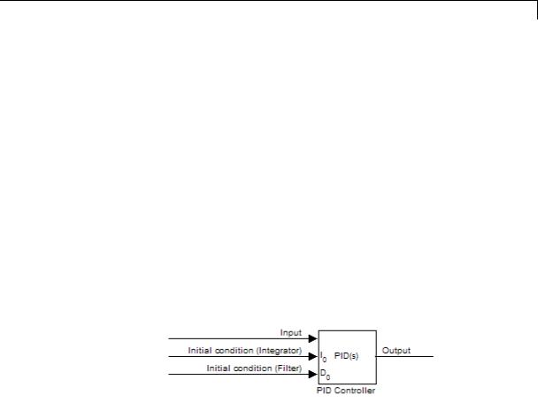
external
Specifies the integrator and filter initial conditions externally. An additional input port appears under the block input for each initial condition: I0 for the integrator and D0 for the filter:
2-1129

PID Controller
Integrator Initial condition
(Available only when Initial conditions Source is internal and the controller includes integral action.) Specify the integrator initial value. Simulink uses the initial condition to initialize the integrator output at the start of a simulation or at a specified trigger event (see “External reset” on page 2-1132). The integrator initial condition, together with the filter initial condition, determines the initial output of the PID controller block.
Default: 0
Simulink does not permit the integrator initial condition to be inf or
NaN.
2-1130

PID Controller
Filter Initial condition
(Available only when Initial conditions Source is internal and the controller includes integral action.) Specify the filter initial value. Simulink uses the initial condition to initialize the filter output at the start of a simulation or at a specified trigger event (see “External reset” on page 2-1132). The filter initial condition, together with the integrator initial condition, determines the initial output of the PID controller block.
Default: 0
Simulink does not permit the filter initial condition to be inf or NaN.
2-1131

PID Controller
External reset
Select the trigger event that resets the integrator and filter outputs to the initial conditions you specify in the Integrator Initial condition and Filter Initial condition fields. Selecting any option other than none enables a reset input on the block for the external reset signal, as shown:
Or, if the Initial conditions Source is External,
Settings
none (Default)
Does not reset the integrator and filter outputs to initial conditions.
rising
Resets the outputs when the reset signal has a rising edge.
falling
Resets the outputs when the reset signal has a falling edge.
either
Resets the outputs when the reset signal either rises or falls.
2-1132
PID Controller
level
Resets and holds the outputs to the initial conditions while the reset signal is nonzero.
Note To be compliant with the Motor Industry Software Reliability Association (MISRA) software standard, your model must use Boolean signals to drive the external reset ports of the PID controller block.
2-1133

PID Controller
Ignore reset when linearizing
Force Simulink linearization commands to ignore any reset mechanism that you have chosen with the External reset menu. Ignoring reset states allows you to linearize a model around an operating point even if that operating point causes the PID Controller block to reset.
Settings
 Off (Default)
Simulink linearization commands do not ignore states
corresponding to the reset mechanism.
 On
On
Simulink linearization commands ignore states corresponding to the reset mechanism.
2-1134

PID Controller
Enable zero-crossing detection
Enable zero-crossing detection in continuous-time models upon reset and upon entering or leaving a saturation state.
Zero-crossing detection can accurately locate signal discontinuities without resorting to excessively small time steps that can lead to lengthy simulation times. If you select Limit output or activate an External reset in your PID Controller block, activating zero-crossing detection can reduce computation time in your simulation. For more information, see “Zero-Crossing Detection” in the Simulink documentation.
Settings
 On (Default)
Uses zero-crossing detection at any of the following events: reset; entering or leaving an upper saturation state; and entering or leaving a lower saturation state.
 Off
Off
Does not use zero-crossing detection.
Enabling zero-crossing detection for the PID Controller block also enables zero-crossing detection for all under-mask blocks that include the zero-crossing detection feature.
2-1135

PID Controller
Limit output
Limit the block output to values you specify as the Lower saturation limit and Upper saturation limit parameters.
Activating this option limits the block output internally to the block, obviating the need for a separate Saturation block after the controller in your Simulink model. It also allows you to activate the block’s built-in anti-windup mechanism (see “Anti-windup method” on page 2-1139).
Settings
 Off (Default)
Does not limit the block output, which equals the weighted sum of the proportional, integral, and derivative actions.
 On
On
Limits the block output to the Lower saturation limit or the Upper saturation limit whenever the weighted sum exceeds those limits. Allows you to select an Anti-windup method.
2-1136

PID Controller
Lower saturation limit
(Available only when you select the Limit output check box.) Specify the lower limit for the block output. The block output is held at
the Lower saturation limit whenever the weighted sum of the proportional, integral, and derivative actions goes below that value.
Default: -inf
2-1137

PID Controller
Upper saturation limit
(Available only when you select the Limit output check box.) Specify the upper limit for the block output. The block output is held at
the Upper saturation limit whenever the weighted sum of the proportional, integral, and derivative actions exceeds that value.
Default: inf
2-1138

PID Controller
Anti-windup method
(Available only when you select the Limit output option and the controller includes integral action.) Select an anti-windup mechanism to discharge the integrator when the block is saturated, which occurs when the sum of the block components exceeds the output limits.
When you select the Limit output check box and the weighted sum of the controller components exceeds the specified output limits, the block output holds at the specified limit. However, the integrator output can continue to grow (integrator wind-up), increasing the difference between the block output and the sum of the block components. Without a mechanism to prevent integrator wind-up, two results are possible:
•If the sign of the input signal never changes, the integrator continues to integrate until it overflows. The overflow value is the maximum or minimum value for the data type of the integrator output.
•If the sign of the input signal changes once the weighted sum has grown beyond the output limits, it can take a long time to discharge the integrator and return the weighted sum within the block saturation limit.
In both cases, controller performance can suffer. To combat the effects of wind-up without an anti-windup mechanism, it may be necessary to detune the controller (for example, by reducing the controller gains), resulting in a sluggish controller. Activating an anti-windup mechanism can improve controller performance.
Settings
none (Default)
Does not use an anti-windup mechanism. This setting may cause the block’s internal signals to be unbounded even if the output appears to be bounded by the saturation limits. This can result in slow recovery from saturation or unexpected overflows.
back-calculation
Discharges the integrator when the block output saturates using the integral-gain feedback loop:
2-1139

PID Controller
You can also specify a value for the Back-calculation coefficient (Kb).
clamping
Stops integration when the sum of the block components exceeds the output limits and the integrator output and block input have the same sign. Resumes integration when the sum of the block components exceeds the output limits and the integrator output and block input have opposite sign. The integrator portion of the block is:
The clamping circuit implements the logic necessary to determine whether integration continues.
2-1140

PID Controller
Back-calculation gain (Kb)
(Available only when the back-calculation Anti-windup method is active.) Specify the gain coefficient of the anti-windup feedback loop.
The back-calculation anti-windup method discharges the integrator on block saturation using a feedback loop having gain coefficient Kb.
Default: 1
2-1141

PID Controller
Ignore saturation when linearizing
Force Simulink linearization commands ignore PID Controller block output limits. Ignoring output limits allows you to linearize a model around an operating point even if that operating point causes the PID Controller block to exceed the output limits.
Settings
 On (Default)
Simulink linearization commands ignore states corresponding to saturation.
 Off
Off
Simulink linearization commands do not ignore states corresponding to saturation.
2-1142
PID Controller
Enable tracking mode
(Available for any controller with integral action.) Activate signal tracking, which lets the output of the PID Controller block follow a tracking signal. Provide the tracking signal to the block at the TR port, which becomes active when you select Enable tracking mode.
When signal tracking is active, the difference between the tracked signal and the block output is fed back to the integrator input with a gain Kt. The structure is illustrated for a PI controller:
2-1143

PID Controller
You can also specify the Tracking coefficient (Kt).
2-1144

PID Controller
Bumpless control transfer
Use signal tracking, for example, to achieve bumpless control transfer in systems that switch between two controllers. You can make one controller track the output of the other controller by connecting the TR port to the signal you want to track. For example:
In this example, the outputs Out1 and Out2 can drive a controlled system (not shown) through a switch that transfers control between the “Active controller” block and the PID Controller block. The signal tracking feature of the PID Controller block provides smooth operation upon transfer of control from one controller to another, ensuring that the two controllers have the same output at the time of transfer.
Multiloop control
Use signal tracking to prevent block wind-up in multiloop control approaches, as this example illustrates:
2-1145

PID Controller
The inner-loop subsystem contains the following blocks:
In this example, the inner loop has an effective gain of 1 when it does not saturate. Without signal tracking, the inner loop winds up in saturation. Signal tracking ensures that the PID Controller output does not exceed the saturated output of the inner loop.
Settings
 Off (Default)
Disables signal tracking and removes TR block input.
 On
On
Enables signal tracking and activates TR input.
2-1146

PID Controller
Tracking gain (Kt)
(Available only when you select Enable tracking mode.) Specify Kt, which is the gain of the signal tracking feedback loop.
Default: 1
2-1147

PID Controller
Parameter data type
Select the data type of the gain parameters P, I, D, N, Kb, and Kt.
See “Data Types Supported by Simulink” in the Simulink documentation for more information.
Settings
Inherit: Inherit via internal rule (Default)
Simulink software chooses a combination of output scaling and data type that requires the smallest amount of memory. This memory requirement accommodates the calculated output range and maintains the output precision of the block and word size of the targeted hardware implementation specified for the model. If the Device type parameter on the Hardware Implementation configuration parameters pane is set to ASIC/FPGA, Simulink software chooses the output data type without regard to hardware constraints. Otherwise, Simulink software chooses the smallest available hardware data type capable of meeting the range and precision constraints. For example, if the block multiplies an input of type int8 by a gain of int16 and ASIC/FPGA is specified as the targeted hardware type, the output data type is sfix24. If Unspecified (assume 32-bit Generic) (a generic 32-bit microprocessor) is the specified target hardware, the output data type is int32.
Inherit: Inherit via back propagation
Use data type of the driving block.
Inherit: Same as input
Use data type of input signal.
double
single
int8
2-1148

PID Controller
uint8
int16
uint16
int32
uint32
fixdt(1,16)
fixdt(1,16,0)
fixdt(1,16,2^0,0)
<data type expression>
Name of a data type object. For example, Simulink.NumericType.
2-1149

PID Controller
Product output data type
Select the product output data type of the gain parameters P, I, D, N, Kb, and Kt .
See “Data Types Supported by Simulink” in the Simulink documentation for more information.
Settings
Inherit: Inherit via internal rule (Default)
Simulink software chooses a combination of output scaling and data type that requires the smallest amount of memory. This memory requirement accommodates the calculated output range and maintains the output precision of the block and word size of the targeted hardware implementation specified for the model. If the Device type parameter on the Hardware Implementation configuration parameters pane is set to ASIC/FPGA, Simulink software chooses the output data type without regard to hardware constraints. Otherwise, Simulink software chooses the smallest available hardware data type capable of meeting the range and precision constraints. For example, if the block multiplies an input of type int8 by a gain of int16 and ASIC/FPGA is specified as the targeted hardware type, the output data type is sfix24. If Unspecified (assume 32-bit Generic) (a generic 32-bit microprocessor) is the specified target hardware, the output data type is int32.
Inherit: Inherit via back propagation
Use data type of the driving block.
Inherit: Same as input
Use data type of input signal.
double
single
int8
2-1150

PID Controller
uint8
int16
uint16
int32
uint32
fixdt(1,16)
fixdt(1,16,0)
fixdt(1,16,2^0,0)
<data type expression>
Name of a data type object. For example, Simulink.NumericType.
2-1151

PID Controller
Summation output data type
Select the summation output data type of the sums Sum, Sum D, Sum I1 , SumI2 ,and SumI3, which are sums computed internally within the block. To see where Simulink computes each of these sums , right-click the PID Controller block in your model and select Look Under Mask:
•Sum is the weighted sum of the proportional, derivative, and integral signals.
•SumD is the sum in the derivative filter feedback loop.
•SumI1 is the sum of the block input signal (weighted by the integral gain I) and SumI2. SumI1 is computed only when Limit output and Anti-windup method back-calculation are active.
•SumI2 is the difference between the weighted sum Sum and the limited block output. SumI2 is computed only when Limit output and Anti-windup method back-calculation are active.
•SumI3 is the difference between the block output and the signal at the block’s tracking input. SumI3 is computed only when you select the Enable tracking mode box.
See “Data Types Supported by Simulink” in the Simulink documentation for more information.
Settings
Inherit: Inherit via internal rule (Default)
Simulink software chooses a combination of output scaling and data type that requires the smallest amount of memory. This memory requirement accommodates the calculated output range and maintains the output precision of the block and word size of the targeted hardware implementation specified for the model. If the Device type parameter on the Hardware Implementation configuration parameters pane is set to ASIC/FPGA, Simulink software chooses the output data type without regard to hardware constraints. Otherwise, Simulink software chooses the smallest available hardware data type capable of meeting the range and precision constraints. For example, if the block multiplies an
2-1152
PID Controller
input of type int8 by a gain of int16 and ASIC/FPGA is specified as the targeted hardware type, the output data type is sfix24. If Unspecified (assume 32-bit Generic) (a generic 32-bit microprocessor) is the specified target hardware, the output data type is int32.
Inherit: Same as first input
Use data type of first input signal.
double
single
int8
uint8
int16
uint16
int32
uint32
fixdt(1,16)
fixdt(1,16,0)
fixdt(1,16,2^0,0)
2-1153

PID Controller
<data type expression>
Name of a data type object. For example, Simulink.NumericType.
2-1154

PID Controller
Accumulator data type
Specify the accumulator data type.
Settings
Default: Inherit: Inherit via internal rule
Inherit: Inherit via internal rule
Use internal rule to determine accumulator data type.
Inherit: Same as first input
Use data type of first input signal.
double
Accumulator data type is double.
single
Accumulator data type is single.
int8
Accumulator data type is int8.
uint8
Accumulator data type is uint8.
int16
Accumulator data type is int16.
uint16
Accumulator data type is uint16.
int32
Accumulator data type is int32.
uint32
Accumulator data type is uint32.
fixdt(1,16,0)
Accumulator data type is fixed point fixdt(1,16,0).
fixdt(1,16,2^0,0)
Accumulator data type is fixed point fixdt(1,16,2^0,0).
2-1155

PID Controller
<data type expression>
The name of a data type object, for example
Simulink.NumericType
Command-Line Information
See “Block-Specific Parameters” on page 8-109 for the command-line information.
See Also
For more information, see “Specify Data Types Using Data Type Assistant”.
2-1156

PID Controller
Integrator output data type
Select the data type of the integrator output.
See “Data Types Supported by Simulink” in the Simulink documentation for more information.
Settings
Inherit: Inherit via internal rule (Default)
Simulink software chooses a combination of output scaling and data type that requires the smallest amount of memory. This memory requirement accommodates the calculated output range and maintains the output precision of the block and word size of the targeted hardware implementation specified for the model. If the Device type parameter on the Hardware Implementation configuration parameters pane is set to ASIC/FPGA, Simulink software chooses the output data type without regard to hardware constraints. Otherwise, Simulink software chooses the smallest available hardware data type capable of meeting the range and precision constraints. For example, if the block multiplies an input of type int8 by a gain of int16 and ASIC/FPGA is specified as the targeted hardware type, the output data type is sfix24. If Unspecified (assume 32-bit Generic) (a generic 32-bit microprocessor) is the specified target hardware, the output data type is int32.
Inherit: Same as input
Use data type of input signal.
double
single
int8
uint8
2-1157

PID Controller
int16
uint16
int32
uint32
fixdt(1,16)
fixdt(1,16,0)
fixdt(1,16,2^0,0)
<data type expression>
Name of a data type object. For example, Simulink.NumericType.
2-1158

PID Controller
Filter output data type
Select the data type of the filter output.
See “Data Types Supported by Simulink” in the Simulink documentation for more information.
Settings
Inherit: Inherit via internal rule (Default)
Simulink software chooses a combination of output scaling and data type that requires the smallest amount of memory. This memory requirement accommodates the calculated output range and maintains the output precision of the block and word size of the targeted hardware implementation specified for the model. If the Device type parameter on the Hardware Implementation configuration parameters pane is set to ASIC/FPGA, Simulink software chooses the output data type without regard to hardware constraints. Otherwise, Simulink software chooses the smallest available hardware data type capable of meeting the range and precision constraints. For example, if the block multiplies an input of type int8 by a gain of int16 and ASIC/FPGA is specified as the targeted hardware type, the output data type is sfix24. If Unspecified (assume 32-bit Generic) (a generic 32-bit microprocessor) is the specified target hardware, the output data type is int32.
Inherit: Same as input
Use data type of input signal.
double
single
int8
uint8
2-1159

PID Controller
int16
uint16
int32
uint32
fixdt(1,16)
fixdt(1,16,0)
fixdt(1,16,2^0,0)
<data type expression>
Name of a data type object. For example, Simulink.NumericType.
2-1160

PID Controller
Saturation output data type
Select the saturation output data type.
See “Data Types Supported by Simulink” in the Simulink documentation for more information.
Settings
Inherit: Same as input (Default)
Use data type of input signal.
double
single
int8
uint8
int16
uint16
int32
uint32
fixdt(1,16)
fixdt(1,16,0)
fixdt(1,16,2^0,0)
2-1161

PID Controller
<data type expression>
Name of a data type object. For example, Simulink.NumericType.
2-1162
PID Controller
Mode
Select the category of data to specify.
Settings
Default: Inherit
Inherit
Inheritance rules for data types. Selecting Inherit enables a second menu/text box to the right. Select one of the following choices:
•Inherit via internal rule (default)
•Inherit via back propagation
•Same as first input
•Same as accumulator
Built in
Built-in data types. Selecting Built in enables a second menu/text box to the right. Select one of the following choices:
•double (default)
•single
•int8
•uint8
•int16
•uint16
•int32
•uint32
Fixed point
Fixed-point data types.
2-1163

PID Controller
Expression
Expressions that evaluate to data types. Selecting Expression enables a second menu/text box to the right, where you can enter the expression.
Dependency
Clicking the Show data type assistant button enables this parameter.
Command-Line Information
See “Block-Specific Parameters” on page 8-109 for the command-line information.
See Also
See “Specify Data Types Using Data Type Assistant”.
2-1164

PID Controller
Mode
Select the category of data to specify.
Settings
Default: Inherit
Inherit
Inheritance rules for data types. Selecting Inherit enables a second menu/text box to the right. Select one of the following choices:
•Inherit via back propagation
•Same as input (default)
Built in
Built-in data types. Selecting Built in enables a second menu/text box to the right. Select one of the following choices:
•double (default)
•single
•int8
•uint8
•int16
•uint16
•int32
•uint32
Fixed point
Fixed-point data types.
Expression
Expressions that evaluate to data types. Selecting Expression enables a second menu/text box to the right, where you can enter the expression.
2-1165

PID Controller
Dependency
Clicking the Show data type assistant button enables this parameter.
Command-Line Information
See “Block-Specific Parameters” on page 8-109 for the command-line information.
See Also
See “Specify Data Types Using Data Type Assistant”.
2-1166

PID Controller
Mode
Select the category of accumulator data to specify
Settings
Default: Inherit
Inherit
Specifies inheritance rules for data types. Selecting Inherit enables a list of possible values:
•Inherit via internal rule (default)
•Same as first input
Built in
Specifies built-in data types. Selecting Built in enables a list of possible values:
•double (default)
•single
•int8
•uint8
•int16
•uint16
•int32
•uint32
Fixed point
Specifies fixed-point data types.
Expression
Specifies expressions that evaluate to data types. Selecting Expression enables you to enter an expression.
Dependency
Clicking the Show data type assistant button for the accumulator data type enables this parameter.
2-1167

PID Controller
Command-Line Information
See “Block-Specific Parameters” on page 8-109 for the command-line information.
See Also
See “Specify Data Types Using Data Type Assistant”.
2-1168

PID Controller
Data type override
Specify data type override mode for this signal.
Settings
Default: Inherit
Inherit
Inherits the data type override setting from its context, that is, from the block, Simulink.Signal object or Stateflow chart in Simulink that is using the signal.
Off
Ignores the data type override setting of its context and uses the fixed-point data type specified for the signal.
Tip
The ability to turn off data type override for an individual data type provides greater control over the data types in your model when you apply data type override. For example, you can use this option to ensure that data types meet the requirements of downstream blocks regardless of the data type override setting.
Dependency
This parameter appears only when the Mode is Built in or Fixed point.
2-1169

PID Controller
Signedness
Specify whether you want the fixed-point data as signed or unsigned.
Settings
Default: Signed
Signed
Specify the fixed-point data as signed.
Unsigned
Specify the fixed-point data as unsigned.
Dependencies
Selecting Mode > Fixed point enables this parameter.
Command-Line Information
See “Block-Specific Parameters” on page 8-109 for the command-line information.
See Also
For more information, see “Specifying a Fixed-Point Data Type”.
2-1170

PID Controller
Signedness
Specify whether you want the fixed-point data to be signed or unsigned.
Settings
Default: Signed
Signed
Specify the fixed-point data to be signed.
Unsigned
Specify the fixed-point data to be unsigned.
Dependencies
Selecting Mode > Fixed point for the accumulator data type enables this parameter.
Command-Line Information
See “Block-Specific Parameters” on page 8-109 for the command-line information.
See Also
See “Specifying a Fixed-Point Data Type” for more information.
2-1171

PID Controller
Scaling
Specify the method for scaling your fixed-point data to avoid overflow conditions and minimize quantization errors.
Settings
Default: Best precision, Binary point, Integer
Binary point
Specify binary point location.
Slope and bias
Enter slope and bias.
Best precision
Specify best-precision values. This option appears for some blocks.
Integer
Specify integer. This setting has the same result as specifying a binary point location and setting fraction length to 0. This option appears for some blocks.
Dependencies
Selecting Mode > Fixed point enables this parameter. Selecting Binary point enables:
•Fraction length
•Calculate Best-Precision Scaling
Selecting Slope and bias enables:
•Slope
•Bias
•Calculate Best-Precision Scaling
Command-Line Information
See “Block-Specific Parameters” on page 8-109 for the command-line information.
2-1172
PID Controller
See Also
For more information, see “Specifying a Fixed-Point Data Type”.
2-1173

PID Controller
Scaling
Specify the method for scaling your fixed-point data to avoid overflow conditions and minimize quantization errors.
Settings
Default: Binary point
Binary point
Specify binary point location.
Slope and bias
Enter slope and bias.
Dependencies
Selecting Mode > Fixed point for the accumulator data type enables this parameter.
Selecting Binary point enables:
• Fraction length
Selecting Slope and bias enables:
•Slope
•Bias
Command-Line Information
See “Block-Specific Parameters” on page 8-109 for the command-line information.
See Also
See “Specifying a Fixed-Point Data Type” for more information.
2-1174

PID Controller
Word length
Specify the bit size of the word that holds the quantized integer.
Settings
Default: 16
Minimum: 0
Maximum: 32
Dependencies
Selecting Mode > Fixed point enables this parameter.
Command-Line Information
See “Block-Specific Parameters” on page 8-109 for the command-line information.
See Also
For more information, see “Specifying a Fixed-Point Data Type”.
2-1175

PID Controller
Word length
Specify the bit size of the word that will hold the quantized integer.
Settings
Default: 16
Minimum: 0
Maximum: 32
Large word sizes represent large values with greater precision than small word sizes.
Dependencies
Selecting Mode > Fixed point for the accumulator data type enables this parameter.
Command-Line Information
See “Block-Specific Parameters” on page 8-109 for the command-line information.
See Also
See “Specifying a Fixed-Point Data Type” for more information.
2-1176

PID Controller
Fraction length
Specify fraction length for fixed-point data type.
Settings
Default: 0
Binary points can be positive or negative integers.
Dependencies
Selecting Scaling > Binary point enables this parameter.
Command-Line Information
See “Block-Specific Parameters” on page 8-109 for the command-line information.
See Also
For more information, see “Specifying a Fixed-Point Data Type”.
2-1177

PID Controller
Fraction length
Specify fraction length for fixed-point data type.
Settings
Default: 0
Binary points can be positive or negative integers.
Dependencies
Selecting Scaling > Binary point for the accumulator data type enables this parameter.
Command-Line Information
See “Block-Specific Parameters” on page 8-109 for the command-line information.
See Also
See “Specifying a Fixed-Point Data Type” for more information.
2-1178

PID Controller
Slope
Specify slope for the fixed-point data type.
Settings
Default: 2^0
Specify any positive real number.
Dependencies
Selecting Scaling > Slope and bias enables this parameter.
Command-Line Information
See “Block-Specific Parameters” on page 8-109 for the command-line information.
See Also
For more information, see “Specifying a Fixed-Point Data Type”.
2-1179

PID Controller
Slope
Specify slope for the fixed-point data type.
Settings
Default: 2^0
Specify any positive real number.
Dependencies
Selecting Scaling > Slope and bias for the accumulator data type enables this parameter.
Command-Line Information
See “Block-Specific Parameters” on page 8-109 for the command-line information.
See Also
See “Specifying a Fixed-Point Data Type” for more information.
2-1180

PID Controller
Bias
Specify bias for the fixed-point data type.
Settings
Default: 0
Specify any real number.
Dependencies
Selecting Scaling > Slope and bias enables this parameter.
Command-Line Information
See “Block-Specific Parameters” on page 8-109 for the command-line information.
See Also
For more information, see “Specifying a Fixed-Point Data Type”.
2-1181

PID Controller
Bias
Specify bias for the fixed-point data type.
Settings
Default: 0
Specify any real number.
Dependencies
Selecting Scaling > Slope and bias for the accumulator data type enables this parameter.
Command-Line Information
See “Block-Specific Parameters” on page 8-109 for the command-line information.
See Also
See “Specifying a Fixed-Point Data Type” for more information.
2-1182
PID Controller
Lock output data type setting against changes by the fixed-point tools
Select to lock the output data type setting of this block against changes by the Fixed-Point Tool and the Fixed-Point Advisor.
Settings
Default: Off
 On
On
Locks the output data type setting for this block.
 Off
Off
Allows the Fixed-Point Tool and the Fixed-Point Advisor to change the output data type setting for this block.
Command-Line Information
See “Block-Specific Parameters” on page 8-109 for the command-line information.
See Also
For more information, see “Use Lock Output Data Type Setting”.
2-1183

PID Controller
Saturate on integer overflow
Specify whether overflows saturate.
Settings
Default: Off
 On
On
Overflows saturate to either the minimum or maximum value that the data type can represent.
For example, an overflow associated with a signed 8-bit integer can saturate to -128 or 127.
 Off
Off
Overflows wrap to the appropriate value that is representable by the data type.
For example, the number 130 does not fit in a signed 8-bit integer and wraps to -126.
Tips
•Consider selecting this check box when your model has possible overflow and you want explicit saturation protection in the generated code.
•Consider clearing this check box when you want to optimize efficiency of your generated code.
Clearing this check box also helps you avoid overspecifying how a block handles out-of-range signals. For more information, see “Checking for Signal Range Errors”.
•When you select this check box, saturation applies to every internal operation on the block, not just the output or result.
•In general, the code generation process can detect when overflow is not possible. In this case, the code generator does not produce saturation code.
2-1184

PID Controller
Command-Line Information
See “Block-Specific Parameters” on page 8-109 for the command-line information.
2-1185

PID Controller
Integer rounding mode
Specify the rounding mode for fixed-point operations.
Settings
Default: Floor
Ceiling
Rounds both positive and negative numbers toward positive infinity. Equivalent to the MATLAB ceil function.
Convergent
Rounds number to the nearest representable value. If a tie occurs, rounds to the nearest even integer. Equivalent to the Fixed-Point Toolbox convergent function.
Floor
Rounds both positive and negative numbers toward negative infinity. Equivalent to the MATLAB floor function.
Nearest
Rounds number to the nearest representable value. If a tie occurs, rounds toward positive infinity. Equivalent to the Fixed-Point Toolbox nearest function.
Round
Rounds number to the nearest representable value. If a tie occurs, rounds positive numbers toward positive infinity and rounds negative numbers toward negative infinity. Equivalent to the Fixed-Point Toolbox round function.
Simplest
Automatically chooses between round toward floor and round toward zero to generate rounding code that is as efficient as possible.
Zero
Rounds number toward zero. Equivalent to the MATLAB fix function.
2-1186

PID Controller
Command-Line Information
See “Block-Specific Parameters” on page 8-109 for the command-line information.
See Also
For more information, see “Rounding” in the Simulink Fixed Point documentation.
2-1187

PID Controller
State name
Assign unique name to each state. The state names apply only to the selected block.
To assign a name to a single state, enter the name between quotes; for example, 'velocity'.
To assign names to multiple states, enter a comma-delimited list surrounded by braces; for example, {'a', 'b', 'c'}. Each name must be unique. To assign state names with a variable that has been defined in the MATLAB workspace, enter the variable without quotes. The variable can be a string, cell, or structure.
Settings
Default: ' ' (no name)
2-1188

PID Controller
State name must resolve to Simulink signal object
Require that state name resolve to Simulink signal object.
Settings
Default: Off
 On
On
Require that state name resolve to Simulink signal object.
 Off
Off
Do not require that state name resolve to Simulink signal object.
Dependencies
State name enables this parameter.
Selecting this check box disables Code generation storage class.
Command-Line Information
See “Block-Specific Parameters” on page 8-109 for the command-line information.
2-1189

PID Controller
Code generation storage class
Select state storage class.
Settings
Default: Auto
Auto
Auto is the appropriate storage class for states that you do not need to interface to external code.
ExportedGlobal
State is stored in a global variable
ImportedExtern
model_private.h declares the state as an extern variable.
ImportedExternPointer
model_private.h declares the state as an extern pointer.
Dependencies
State name enables this parameter.
Setting this parameter to ExportedGlobal, ImportedExtern, or
ImportedExternPointer enables Code generation storage type qualifier.
Command-Line Information
See “Block-Specific Parameters” on page 8-109 for the command-line information.
See Also
“State Storage Classes” in the Simulink Coder documentation.
2-1190

PID Controller
Characteristics
See Also
Code generation storage type qualifier
Specify the Simulink Coder storage type qualifier.
Settings
Default: ' '
If left blank, no qualifier is assigned.
Dependency
Setting Code generation storage class to ExportedGlobal,
ImportedExtern, or ImportedExternPointer enables this parameter.
Command-Line Information
See “Block-Specific Parameters” on page 8-109 for the command-line information.
Direct Feedthrough |
The following ports support direct |
|
feedthrough: |
|
• Reset port |
|
• Integrator and filter initial condition |
|
port |
|
• Input port, for every integration |
|
method except Forward Euler |
Sample Time |
Specified in the Sample time |
|
parameter |
Scalar Expansion |
Supported for gain parameters P, I, and |
|
D and for filter coefficient N |
States |
Inherited from driving block and |
|
parameters |
Dimensionalized |
Yes |
Zero-Crossing Detection |
Yes (in continuous-time domain) |
|
|
PID Controller (2 DOF), Gain, Integrator, Discrete-Time Integrator, Derivative, Discrete Derivative.
2-1191

PID Controller (2 DOF)
Purpose
Library
Description
Simulate continuousor discrete-time two-degree-of-freedom PID controllers
Continuous, Discrete
Implement a continuousor discrete-time two-degree-of-freedom controller (PID, PI, or PD) in your Simulink model. The PID Controller (2DOF) block allows you to implement setpoint weighting in your controller to achieve both smooth setpoint tracking and good disturbance rejection.
The PID Controller (2DOF) block generates an output signal based on the difference between a reference signal and a measured system
output. The block computes a weighted difference signal for each of the proportional, integral, and derivative actions according to the setpoint weights you specify. The block output is the sum of the proportional, integral, and derivative actions on the respective difference signals, where each action is weighted according to the gain parameters. A first-order pole filters the derivative action. Controller gains are tunable either manually or automatically. Automatic tuning requires Simulink Control Design software (PID Tuner or SISO Design Tool).
Configurable options in the PID Controller (2DOF) block include:
•Controller type (PID, PI, or PD)
•Controller form (Parallel or Ideal)
•Time domain (continuous or discrete)
•Initial conditions and reset trigger
•Output saturation limits and built-in anti-windup mechanism
•Signal tracking for bumpless control transfer and multiloop control
In one common implementation, the PID Controller (2DOF) block operates in the feedforward path of the feedback loop. The block receives a reference signal at the Ref input and a measured system output at the other input. For example:
2-1192
PID Controller (2 DOF)
Data Type
Support
Parameters
For a single-input block that accepts an error signal (a difference between a setpoint and a system output), see the PID Controller block reference page.
You can generate code to implement your controller using any Simulink data type, including fixed-point data types. (Code generation requires Simulink Coder software; fixed-point implementation requires the Fixed-Point Toolbox product.)
For an example illustrating an application of the PID Controller (2 DOF) block, see the Simulink example Two Degree-of-Freedom PID Control for Setpoint Tracking.
The PID Controller (2DOF) block accepts real signals of any numeric data type that Simulink software supports, including fixed-point data types. See “Data Types Supported by Simulink” in the Simulink documentation for more information.
The following table summarizes the PID Controller (2DOF)block parameters, accessible via the block parameter dialog box.
2-1193

PID Controller (2 DOF)
|
Task |
Parameters |
|
|
Choose controller form and type. |
• Controller Form in Main tab |
|
|
|
• Controller |
|
|
Choose discrete or continuous time. |
• Time-domain |
|
|
|
• Sample time |
|
|
Choose an integration method (discrete |
• Integrator method |
|
|
time). |
• Filter method |
|
|
|
|
|
|
Set and tune controller gains. |
• Proportional (P) in Main tab |
|
|
|
• Integral (I) in Main tab |
|
|
|
• Derivative (D) in Main tab |
|
|
|
• Filter coefficient (N) in Main tab |
|
|
|
• Setpoint weight (b) in Main tab |
|
|
|
• Setpoint weight (c) in Main tab |
|
|
Set integrator and filter initial conditions. |
• Initial conditions Source in Main tab |
|
|
|
• Integrator Initial condition in Main |
|
|
|
tab |
|
|
|
• Filter Initial condition in Main tab |
|
|
|
• External reset in Main tab |
|
|
|
• Ignore reset when linearizing in Main |
|
|
|
tab |
|
2-1194

PID Controller (2 DOF)
|
Task |
Parameters |
|
|
Limit block output. |
• Limit output in PID Advanced tab |
|
|
|
• Lower saturation limit in PID |
|
|
|
Advanced tab |
|
|
|
• Upper saturation limit in PID |
|
|
|
Advanced tab |
|
|
|
• Ignore saturation when linearizing |
|
|
|
in PID Advanced tab |
|
|
Configure anti-windup mechanism (when |
• Anti-windup method in PID Advanced |
|
|
you limit block output). |
tab |
|
|
|
• Back-calculation gain (Kb) in PID |
|
|
|
Advanced tab |
|
|
Enable signal tracking. |
• Enable tracking mode in PID |
|
|
|
Advanced tab |
|
|
|
• Tracking gain (Kt) in PID Advanced |
|
|
|
tab |
|
|
Configure data types. |
• Parameter data type in Data Type |
|
|
|
Attributes tab |
|
|
|
• Product output data type in Data |
|
|
|
Type Attributes tab |
|
|
|
• Summation output data type in Data |
|
|
|
Type Attributes tab |
|
|
|
• Accumulator data type in Data Type |
|
|
|
Attributes tab |
|
|
|
• Integrator output data type in Data |
|
|
|
Type Attributes tab |
|
|
|
• Filter output data type in Data Type |
|
|
|
Attributes tab |
|
2-1195

PID Controller (2 DOF)
Task |
Parameters |
|
|
|
• Saturation output data type in Data |
|
Type Attributes tab |
|
• Lock output data type setting against |
|
changes by the fixed-point tools in |
|
Data Type Attributes tab |
|
• Saturate on integer overflow in Data |
|
Type Attributes tab |
|
• Integer rounding mode in Data Type |
|
Attributes tab |
Configure block for code generation. |
• State name in State Attributes tab |
|
• State name must resolve to Simulink |
|
signal object in State Attributes tab |
|
• Code generation storage class in |
|
State Attributes tab |
|
• Code generation storage type |
|
qualifier in State Attributes tab |
2-1196

PID Controller (2 DOF)
Controller form
Select the controller form.
Settings
Parallel (Default)
Selects a controller form in which the proportional, integral, and derivative gains P, I, and D operate independently. The filter coefficient N sets the location of the pole in the derivative filter.
Parallel two-degree-of-freedom PID controller, where input 1 receives a reference signal and input 2 receives feedback from the measured system output:
The parallel two-degree-of-freedom PID controller can be equivalently modeled by the following block diagram:
2-1197
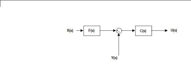
PID Controller (2 DOF)
R(s) represents the reference signal and Y(s) represents the feedback from measured system output. In this model, C(s) is a single degree-of-freedom controller, and F(s) acts as a prefilter on the reference signal. For a parallel two-degree-of-freedom PID controller in the Continuous-time Time-domain, the transfer functions F(s) and C(s) are:
F (s) = |
(bP + cDN)s2 |
+ (bPN + I )s + IN |
||
(P + DN)s2 |
+ (PN + I )s + IN |
|||
par |
||||
Cpar (s) = |
(P + DN)s2 + (PN + I )s + IN |
|
||
s(s + N) |
||||
|
||||
where b and c are the Setpoint weight parameters.
Alternatively, the parallel two-degree-of-freedom PID controller can be modeled by the following block diagram:
2-1198
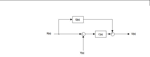
PID Controller (2 DOF)
R(s), Y(s), and C(s) are as discussed previously. In this realization, Q(s) acts as feed-forward conditioning on the reference signal R(s). For a parallel PID controller in the Continuous-time Time-domain, the transfer function Q(s) is:
Qpar (s) = |
((b − 1)P + (c − 1)DN )s + (b − 1)PN |
|
s + N |
||
|
Ideal
Selects a controller form in which the proportional gain P acts on the sum of all actions.
Ideal two-degree-of-freedom PID controller, where input 1 receives a reference signal and input 2 receives feedback from the measured system output:
2-1199

PID Controller (2 DOF)
Similarly to the parallel controller form discussed previously, the ideal two-degree-of-freedom PID controller can be modeled as a single degree-of-freedom controller C(s) with a prefilter F(s). For an ideal two-degree-of-freedom PID controller in the Continuous-time Time-domain, the transfer functions F(s) and C(s) are:
F (s) = |
(b + cDN)s2 |
+ (bN + I )s + IN |
|||
(1+ DN)s2 |
+ (N + I )s + IN |
||||
id |
|||||
C (s) = P |
(1+ DN)s |
2 + (N + I )s + IN |
|
||
s(s + N) |
|||||
id |
|
||||
|
|
|
|
||
where b and c are the Setpoint weight parameters.
Alternatively, modeling the ideal two-degree-of-freedom PID controller as a one-degree-of-freedom controller C(s) with
2-1200

PID Controller (2 DOF)
feed-forward conditioning Q(s) on the reference signal gives, in continuous-time:
Q (s) = P |
((b − 1) + (c − 1)DN )s + (b − 1)N |
|
s + N |
||
id |
||
|
The controller transfer function for the current settings is displayed in the block dialog box.
2-1201

PID Controller (2 DOF)
Controller
Specify the controller type.
Settings
PID (Default)
Implements a controller with proportional, integral, and
derivative action.
PI
Implements a controller with proportional and integral action.
PD
Implements a controller with proportional and derivative action. The controller transfer function for the current settings is displayed in the block dialog box.
2-1202
PID Controller (2 DOF)
Time-domain
Select continuous or discrete time domain. The appearance of the block changes to reflect your selection.
Settings
Continuous-time (Default)
Selects the continuous-time representation.
Discrete-time
Selects the discrete-time representation. Selecting Discrete-time also allows you to specify the:
•Sample time, which is the discrete interval between samples.
•Discrete integration methods for the integrator and the derivative filter using the Integrator method and Filter method menus.
2-1203

PID Controller (2 DOF)
Integrator method
(Available only when you set Time-domain to Discrete-time.) Specify the method used to compute the integrator output. For more information about discrete-time integration methods, see the Discrete-Time Integrator block reference page.
Settings
Forward Euler (Default)
Selects the Forward Rectangular (left-hand) approximation.
•This method is best for small sampling times, where the Nyquist limit is large compared to the bandwidth of the controller. For larger sampling times, the Forward Euler method can result in instability, even when discretizing a system that is stable in continuous time.
Backward Euler
Selects the Backward Rectangular (right-hand) approximation.
•If you are generating code using Simulink Coder software or the Fixed-Point Toolbox product and you activate the
Back-calculation Anti-windup method, this integration method can cause algebraic loops in your controller. Algebraic loops can lead to slower performance of generated code. For more information about algebraic loops in Simulink models, see “Algebraic Loops” in the Simulink documentation.
•An advantage of the Backward Euler method is that discretizing a stable continuous-time system using this method always yields a stable discrete-time result.
Trapezoidal
Selects the Bilinear approximation.
•If you are generating code using Simulink Coder software or the Fixed-Point Toolbox product and you activate the
Back-calculation Anti-windup method, this integration method can cause algebraic loops in your controller. Algebraic loops can lead to slower performance of generated code. For
2-1204

PID Controller (2 DOF)
more information about algebraic loops in Simulink models, see “Algebraic Loops” in the Simulink documentation.
•An advantage of the Trapezoidal method is that discretizing a stable continuous-time system using this method always yields a stable discrete-time result. Of all available integration methods, the Trapezoidal method yields the closest match between frequency-domain properties of the discretized system and the corresponding continuous-time system.
2-1205

PID Controller (2 DOF)
Filter method
(Available only when you set Time-domain to Discrete-time.) Specify the method used to compute the derivative filter output. For more information about discrete-time integration methods, see the Discrete-Time Integrator block reference page.
Settings
Forward Euler (Default)
Selects the Forward Rectangular (left-hand) approximation.
•This method is best for small sampling times, where the Nyquist limit is large compared to the bandwidth of the controller. For larger sampling times, the Forward Euler method can result in instability, even when discretizing a system that is stable in continuous time.
Backward Euler
Selects the Backward Rectangular (right-hand) approximation.
•If you are generating code using Simulink Coder software or the Fixed-Point Toolbox product, this filter method can cause algebraic loops in your controller. Algebraic loops can lead to slower performance of generated code. For more information about algebraic loops in Simulink models, see “Algebraic Loops” in the Simulink documentation.
•An advantage of the Backward Euler method is that discretizing a stable continuous-time system using this method always yields a stable discrete-time result. Any filter parameter value N > 0 yields a stable result with this method.
Trapezoidal
Selects the Bilinear approximation.
•If you are generating code using Simulink Coder software or the Fixed-Point Toolbox product, this filter method can cause algebraic loops in your controller. Algebraic loops can lead to slower performance of generated code. For more information about algebraic loops in Simulink models, see “Algebraic Loops” in the Simulink documentation.
2-1206

PID Controller (2 DOF)
•An advantage of the Trapezoidal method is that discretizing a stable continuous-time system using this method always yields a stable discrete-time result. Any filter parameter value N > 0 yields a stable result with this method. Of all available filter methods, the Trapezoidal method yields the closest match between frequency-domain properties of the discretized system and the corresponding continuous-time system.
2-1207

PID Controller (2 DOF)
Sample time (-1 for inherited)
(Available only when you set Time-domain to Discrete-time.) Specify the discrete interval between samples.
Settings
Default: 1
By default, the block uses a discrete sample time of 1. To specify a different sample time, enter another discrete value, such as 0.1.
If you specify a value of –1, the PID Controller (2DOF) block inherits the sample time from upstream blocks. Do not enter a value of 0; to implement a continuous-time controller, select the Time-domain
Continuous-time.
See “Specify Sample Time” in the online documentation for more information.
2-1208

PID Controller (2 DOF)
Proportional (P)
Specify the proportional gain P.
Default: 1
Enter a finite, real gain value into the Proportional (P) field. Use either scalar or vector gain values. For a parallel PID Controller form, the proportional action is independent of the integral and derivative actions. For an ideal PID Controller form, the proportional action acts on the integral and derivative actions. See “Controller form” on page 2-1197 for more information about the role of P in the controller transfer function.
When you have Simulink Control Design software installed, you can automatically tune the controller gains using the PID Tuner or the SISO Design Tool. See “Choosing a Compensator Design Approach”.
2-1209

PID Controller (2 DOF)
Integral (I)
(Available for PID and PI controllers.) Specify the integral gain I.
Default: 1
Enter a finite, real gain value into the Integral (I) field. Use either scalar or vector gain values.
When you have Simulink Control Design software installed, you can automatically tune the controller gains using the PID Tuner or the SISO Design Tool. See “Choosing a Compensator Design Approach”.
2-1210

PID Controller (2 DOF)
Derivative (D)
(Available for PID and PD controllers.) Specify the derivative gain D.
Default: 0
Enter a finite, real gain value into the Derivative (D) field. Use either scalar or vector gain values.
When you have Simulink Control Design software installed, you can automatically tune the controller gains using the PID Tuner or the SISO Design Tool. See “Choosing a Compensator Design Approach”.
2-1211

PID Controller (2 DOF)
Filter coefficient (N)
Specifies the filter coefficient of the controller.
(Available for PID and PD controllers.) Specify the filter coefficient N, which determines the pole location of the filter in the derivative action:
The filter pole falls at s = -N in the Continuous-time Time-domain. For Discrete-time, the location of the pole depends on which Filter method you select (for sampling time Ts):
•Forward Euler: zpole = 1 − NTs
•Backward Euler:
zpole = |
|
1 |
|
+ NTs |
|
1 |
||
• Trapezoidal:
zpole = |
1 − NTs / 2 |
|
1 + NTs / 2 |
||
|
||
Default: 100. |
||
2-1212
PID Controller (2 DOF)
Enter a finite, real gain value into the Filter Coefficient (N) field. Use either scalar or vector gain values. Note that the PID controller (2DOF) block does not support N = inf (ideal unfiltered derivative).
When you have Simulink Control Design software installed, you can automatically tune the controller gains using the PID Tuner or the SISO Design Tool. See “Choosing a Compensator Design Approach”. Automatic tuning requires N > 0.
2-1213

PID Controller (2 DOF)
Setpoint weight (b)
Specify the proportional setpoint weight b.
Default: 1
Enter the proportional setpoint weight value into the Setpoint weight
(b) field. Setting b = 0 eliminates the proportional action on the reference signal, which can reduce overshoot in the system response to step changes in the setpoint.
The following diagrams show the role of Setpoint weight (b) in Parallel and Ideal PID controllers. See “Controller form” on page 2-1197 for a discussion of the corresponding transfer functions.
Parallel Two-Degree-of-Freedom PID Controller
2-1214

PID Controller (2 DOF)
Ideal Two-Degree-of-Freedom PID Controller
2-1215

PID Controller (2 DOF)
Setpoint weight (c)
(Available for PID and PD controllers.) Specify the derivative setpoint weight c.
Enter the derivative setpoint weight value into the Setpoint weight (c) field. To implement a controller that achieves both effective disturbance rejection and smooth setpoint tracking without excessive transient response, set c = 0. Setting c = 0 yields a controller with derivative action on the measured system response but not on the reference input.
The following diagrams show the role of Setpoint weight (c) in Parallel and Ideal PID controllers. See “Controller form” on page 2-1197 for a discussion of the corresponding transfer functions.
Parallel Two-Degree-of-Freedom PID Controller
2-1216

PID Controller (2 DOF)
Ideal Two-Degree-of-Freedom PID Controller
2-1217

PID Controller (2 DOF)
Initial conditions Source
Select the source of the integrator and filter initial conditions. Simulink uses initial conditions to initialize the integrator and filter output at the start of a simulation or at a specified trigger event (see “External reset” on page 2-1221). The integrator and filter initial conditions in turn determine the initial block output.
Settings
internal (Default)
Specifies the integrator and filter initial conditions explicitly using the Integrator Initial condition and Filter Initial condition parameters.
external
Specifies the integrator and filter initial conditions externally. An additional input port appears under the block inputs for each initial condition: I0 for the integrator and D0 for the filter:
2-1218

PID Controller (2 DOF)
Integrator Initial condition
(Available only when Initial conditions Source is internal and the controller includes integral action.) Specify the integrator initial value. Simulink uses the initial condition to initialize the integrator output at the start of a simulation or at a specified trigger event (see “External reset” on page 2-1221). The integrator initial condition, together with the filter initial condition, determines the initial output of the PID Controller (2DOF) block.
Default: 0
Simulink does not permit the integrator initial condition to be inf or
NaN.
2-1219

PID Controller (2 DOF)
Filter Initial condition
(Available only when Initial conditions Source is internal and the controller includes integral action.) Specify the filter initial value. Simulink uses the initial condition to initialize the filter output at the start of a simulation or at a specified trigger event (see “External reset” on page 2-1221). The filter initial condition, together with the integrator initial condition, determines the initial output of the PID Controller (2DOF) block.
Default: 0
Simulink does not permit the filter initial condition to be inf or NaN.
2-1220

PID Controller (2 DOF)
External reset
Select the trigger event that resets the integrator and filter outputs to the initial conditions you specify in the Integrator Initial condition and Filter Initial condition fields. Selecting any option other than none enables a reset input on the block for the external reset signal, as shown:
Or, if the Initial conditions Source is External:
Settings
none (Default)
Does not reset the integrator and filter outputs to initial conditions.
rising
Resets the outputs when the reset signal has a rising edge.
falling
Resets the outputs when the reset signal has a falling edge.
2-1221

PID Controller (2 DOF)
either
Resets the outputs when the reset signal either rises or falls.
level
Resets and holds the outputs to the initial conditions while the reset signal is nonzero.
Note To be compliant with the Motor Industry Software Reliability Association (MISRA) software standard, your model must use Boolean signals to drive the external reset ports of the PID controller (2DOF) block.
2-1222
PID Controller (2 DOF)
Ignore reset when linearizing
Force Simulink linearization commands to ignore any reset mechanism that you have chosen with the External reset menu. Ignoring reset states allows you to linearize a model around an operating point even if that operating point causes the PID Controller (2DOF) block to reset.
Settings
 Off (Default)
Simulink linearization commands do not ignore states
corresponding to the reset mechanism.
 On
On
Simulink linearization commands ignore states corresponding to the reset mechanism.
2-1223

PID Controller (2 DOF)
Enable zero-crossing detection
Enable zero-crossing detection in continuous-time models upon reset and upon entering or leaving a saturation state.
Zero-crossing detection can accurately locate signal discontinuities without resorting to excessively small time steps that can lead to lengthy simulation times. If you select Limit output or activate an External reset in your PID Controller (2DOF) block, activating
zero-crossing detection can reduce computation time in your simulation. For more information, see “Zero-Crossing Detection” in the Simulink documentation.
Settings
 On (Default)
Uses zero-crossing detection at any of the following events: reset; entering or leaving an upper saturation state; and entering or leaving a lower saturation state.
 Off
Off
Does not use zero-crossing detection.
Enabling zero-crossing detection for the PID Controller (2DOF) block also enables zero-crossing detection for all under-mask blocks that include the zero-crossing detection feature.
2-1224

PID Controller (2 DOF)
Limit output
Limit the block output to values you specify as the Lower saturation limit and Upper saturation limit parameters.
Activating this option limits the block output internally to the block, obviating the need for a separate Saturation block after the controller in your Simulink model. It also allows you to activate the built-in anti-windup mechanism (see “Anti-windup method” on page 2-1228).
Settings
 Off (Default)
Does not limit the block output, which is the weighted sum of the proportional, integral, and derivative actions.
 On
On
Limits the block output to the Lower saturation limit or the Upper saturation limit whenever the weighted sum exceeds those limits. Allows you to select an Anti-windup method.
2-1225

PID Controller (2 DOF)
Lower saturation limit
(Available only when you select the Limit Output box.) Specify the lower limit for the block output. The block output is held at the Lower saturation limit whenever the weighted sum of the proportional, integral, and derivative actions goes below that value.
Default: -inf
2-1226

PID Controller (2 DOF)
Upper saturation limit
(Available only when you select the Limit Output box.) Specify the upper limit for the block output. The block output is held at the Upper saturation limit whenever the weighted sum of the proportional, integral, and derivative actions exceeds that value.
Default: inf
2-1227

PID Controller (2 DOF)
Anti-windup method
(Available only when you select the Limit Output option and the controller includes integral action.) Select an anti-windup mechanism to discharge the integrator when the block is saturated, which occurs when the sum of the block components exceeds the output limits.
When you select the Limit output check box and the weighted sum of the controller components exceeds the specified output limits, the block output holds at the specified limit. However, the integrator output can continue to grow (integrator wind-up), increasing the difference between the block output and the sum of the block components. Without a mechanism to prevent integrator wind-up, two results are possible:
•If the sign of the input signal never changes, the integrator continues to integrate until it overflows. The overflow value is the maximum or minimum value for the data type of the integrator output.
•If the sign of the input signal changes once the weighted sum has grown beyond the output limits, it can take a long time to discharge the integrator and return the weighted sum within the block saturation limit.
In both cases, controller performance can suffer. To combat the effects of wind-up without an anti-windup mechanism, it may be necessary to detune the controller (for example, by reducing the controller gains), resulting in a sluggish controller. Activating an anti-windup mechanism can improve controller performance.
Settings
none (Default)
Does not use an anti-windup mechanism. This setting can cause the block’s internal signals to be unbounded even if the output appears to be bounded by the saturation limits. This can result in slow recovery from saturation or unexpected overflows.
back-calculation
Discharges the integrator when the block output saturates using the integral-gain feedback loop:
2-1228

PID Controller (2 DOF)
You can also specify a value for the Back-calculation coefficient (Kb).
clamping
Stops integration when the sum of the block components exceeds the output limits and the integrator output and block input have the same sign. Resumes integration when the sum of the block components exceeds the output limits and the integrator output and block input have opposite sign. The integrator portion of the block is:
The clamping circuit implements the logic necessary to determine whether integration continues.
2-1229

PID Controller (2 DOF)
Back-calculation gain (Kb)
(Available only when the back-calculation Anti-windup method is active.) Specify the gain coefficient of the anti-windup feedback loop.
The back-calculation anti-windup method discharges the integrator on block saturation using a feedback loop having gain coefficient Kb.
Default: 1
2-1230

PID Controller (2 DOF)
Ignore saturation when linearizing
Force Simulink linearization commands ignore PID Controller (2DOF) block output limits. Ignoring output limits allows you to linearize a model around an operating point even if that operating point causes the PID Controller (2DOF) block to exceed the output limits.
Settings
 On (Default)
Simulink linearization commands ignore states corresponding to saturation.
 Off
Off
Simulink linearization commands do not ignore states corresponding to saturation.
2-1231

PID Controller (2 DOF)
Enable tracking mode
(Available for any controller with integral action.) Activate signal tracking, which lets the output of the PID Controller (2DOF) block follow a tracking signal. Provide the tracking signal to the block at the TR port, which becomes active when you select Enable tracking mode.
When signal tracking is active, the difference between the tracked signal and the block output is fed back to the integrator input with a gain Kt. You can also specify the value of the Tracking coefficient (Kt).
For information about using tracking mode to implement bumpless control transfer scenarios and multiloop controllers, see “Enable tracking mode” on page 2-1143 in the PID Controller reference page.
Settings
 Off (Default)
Disables signal tracking and removes TR block input.
 On
On
Enables signal tracking and activates TR input.
2-1232
PID Controller (2 DOF)
Tracking gain (Kt)
(Available only when you select Enable tracking mode.) Specify Kt, which is the gain of the signal tracking feedback loop.
Default: 1
2-1233

PID Controller (2 DOF)
Parameter data type
Select the data type of the gain parameters P, I, D, N, Kb, and Kt and the setpoint weighting parameters b and c.
See “Data Types Supported by Simulink” in the Simulink documentation for more information.
Settings
Inherit: Inherit via internal rule (Default)
Simulink software chooses a combination of output scaling and data type that requires the smallest amount of memory. This memory requirement accommodates the calculated output range and maintains the output precision of the block and word size of the targeted hardware implementation specified for the model. If the Device type parameter on the Hardware Implementation configuration parameters pane is set to ASIC/FPGA, Simulink software chooses the output data type without regard to hardware constraints. Otherwise, Simulink software chooses the smallest available hardware data type capable of meeting the range and precision constraints. For example, if the block multiplies an input of type int8 by a gain of int16 and ASIC/FPGA is specified as the targeted hardware type, the output data type is sfix24. If Unspecified (assume 32-bit Generic) (a generic 32-bit microprocessor) is the specified target hardware, the output data type is int32.
Inherit: Inherit via back propagation
Use data type of the driving block.
Inherit: Same as input
Use data type of input signal.
double
single
int8
2-1234

PID Controller (2 DOF)
uint8
int16
uint16
int32
uint32
fixdt(1,16)
fixdt(1,16,0)
fixdt(1,16,2^0,0)
<data type expression>
Name of a data type object. For example, Simulink.NumericType.
2-1235

PID Controller (2 DOF)
Product output data type
Select the product output data type of the gain parameters P, I, D, N, Kb, and Kt and the setpoint weighting parameters b and c .
See “Data Types Supported by Simulink” in the Simulink documentation for more information.
Settings
Inherit: Inherit via internal rule (Default)
Simulink software chooses a combination of output scaling and data type that requires the smallest amount of memory. This memory requirement accommodates the calculated output range and maintains the output precision of the block and word size of the targeted hardware implementation specified for the model. If the Device type parameter on the Hardware Implementation configuration parameters pane is set to ASIC/FPGA, Simulink software chooses the output data type without regard to hardware constraints. Otherwise, Simulink software chooses the smallest available hardware data type capable of meeting the range and precision constraints. For example, if the block multiplies an input of type int8 by a gain of int16 and ASIC/FPGA is specified as the targeted hardware type, the output data type is sfix24. If Unspecified (assume 32-bit Generic) (a generic 32-bit microprocessor) is the specified target hardware, the output data type is int32.
Inherit: Inherit via back propagation
Use data type of the driving block.
Inherit: Same as input
Use data type of input signal.
double
single
int8
2-1236

PID Controller (2 DOF)
uint8
int16
uint16
int32
uint32
fixdt(1,16)
fixdt(1,16,0)
fixdt(1,16,2^0,0)
<data type expression>
Name of a data type object. For example, Simulink.NumericType.
2-1237

PID Controller (2 DOF)
Summation output data type
Select the summation output data type of the sums Sum, Sum1,
Sum2, Sum3, Sum D, Sum I1 , SumI2 ,and SumI3, which are sums computed internally within the block. To see where Simulink computes each of these sums , right-click the PID Controller (2DOF) block in your model and select Look Under Mask:
•Sum is the weighted sum of the proportional, derivative, and integral signals.
•Sum1 is the difference between the reference input weighted by b and the measured system response.
•Sum2 is the difference between the reference input weighted by c and the measured system response.
•Sum3 is the difference between the unweighted reference input and the measured system response.
•SumD is the sum in the derivative filter feedback loop.
•SumI1 is the sum of the block input signal (weighted by the integral gain I) and SumI2. SumI1 is computed only when Limit output and Anti-windup method back-calculation are active.
•SumI2 is the difference between the weighted sum Sum and the limited block output. SumI2 is computed only when Limit output and Anti-windup method back-calculation are active.
•SumI3 is the difference between the block output and the signal at the block’s tracking input. SumI3 is computed only when you select the Enable tracking mode box.
See “Data Types Supported by Simulink” in the Simulink documentation for more information.
Settings
Inherit: Inherit via internal rule (Default)
Simulink software chooses a combination of output scaling and data type that requires the smallest amount of memory. This memory requirement accommodates the calculated output range
2-1238

PID Controller (2 DOF)
and maintains the output precision of the block and word size of the targeted hardware implementation specified for the model. If the Device type parameter on the Hardware Implementation configuration parameters pane is set to ASIC/FPGA, Simulink software chooses the output data type without regard to hardware constraints. Otherwise, Simulink software chooses the smallest available hardware data type capable of meeting the range and precision constraints. For example, if the block multiplies an input of type int8 by a gain of int16 and ASIC/FPGA is specified as the targeted hardware type, the output data type is sfix24. If Unspecified (assume 32-bit Generic) (a generic 32-bit microprocessor) is the specified target hardware, the output data type is int32.
Inherit: Same as first input
Use data type of first input signal.
double
single
int8
uint8
int16
uint16
int32
uint32
2-1239

PID Controller (2 DOF)
fixdt(1,16)
fixdt(1,16,0)
fixdt(1,16,2^0,0)
<data type expression>
Name of a data type object. For example, Simulink.NumericType.
2-1240

PID Controller (2 DOF)
Accumulator data type
Specify the accumulator data type.
Settings
Default: Inherit: Inherit via internal rule
Inherit: Inherit via internal rule
Use internal rule to determine accumulator data type.
Inherit: Same as first input
Use data type of first input signal.
double
Accumulator data type is double.
single
Accumulator data type is single.
int8
Accumulator data type is int8.
uint8
Accumulator data type is uint8.
int16
Accumulator data type is int16.
uint16
Accumulator data type is uint16.
int32
Accumulator data type is int32.
uint32
Accumulator data type is uint32.
fixdt(1,16,0)
Accumulator data type is fixed point fixdt(1,16,0).
fixdt(1,16,2^0,0)
Accumulator data type is fixed point fixdt(1,16,2^0,0).
2-1241

PID Controller (2 DOF)
<data type expression>
The name of a data type object, for example
Simulink.NumericType
Command-Line Information
See “Block-Specific Parameters” on page 8-109 for the command-line information.
See Also
For more information, see “Specify Data Types Using Data Type Assistant”.
2-1242
PID Controller (2 DOF)
Integrator output data type
Select the data type of the integrator output.
See “Data Types Supported by Simulink” in the Simulink documentation for more information.
Settings
Inherit: Inherit via internal rule (Default)
Simulink software chooses a combination of output scaling and data type that requires the smallest amount of memory. This memory requirement accommodates the calculated output range and maintains the output precision of the block and word size of the targeted hardware implementation specified for the model. If the Device type parameter on the Hardware Implementation configuration parameters pane is set to ASIC/FPGA, Simulink software chooses the output data type without regard to hardware constraints. Otherwise, Simulink software chooses the smallest available hardware data type capable of meeting the range and precision constraints. For example, if the block multiplies an input of type int8 by a gain of int16 and ASIC/FPGA is specified as the targeted hardware type, the output data type is sfix24. If Unspecified (assume 32-bit Generic) (a generic 32-bit microprocessor) is the specified target hardware, the output data type is int32.
Inherit: Same as input
Use data type of input signal.
double
single
int8
uint8
2-1243

PID Controller (2 DOF)
int16
uint16
int32
uint32
fixdt(1,16)
fixdt(1,16,0)
fixdt(1,16,2^0,0)
<data type expression>
Name of a data type object. For example, Simulink.NumericType.
2-1244

PID Controller (2 DOF)
Filter output data type
Select the data type of the filter output.
See “Data Types Supported by Simulink” in the Simulink documentation for more information.
Settings
Inherit: Inherit via internal rule (Default)
Simulink software chooses a combination of output scaling and data type that requires the smallest amount of memory. This memory requirement accommodates the calculated output range and maintains the output precision of the block and word size of the targeted hardware implementation specified for the model. If the Device type parameter on the Hardware Implementation configuration parameters pane is set to ASIC/FPGA, Simulink software chooses the output data type without regard to hardware constraints. Otherwise, Simulink software chooses the smallest available hardware data type capable of meeting the range and precision constraints. For example, if the block multiplies an input of type int8 by a gain of int16 and ASIC/FPGA is specified as the targeted hardware type, the output data type is sfix24. If Unspecified (assume 32-bit Generic) (a generic 32-bit microprocessor) is the specified target hardware, the output data type is int32.
Inherit: Same as input
Use data type of input signal.
double
single
int8
uint8
2-1245

PID Controller (2 DOF)
int16
uint16
int32
uint32
fixdt(1,16)
fixdt(1,16,0)
fixdt(1,16,2^0,0)
<data type expression>
Name of a data type object. For example, Simulink.NumericType.
2-1246

PID Controller (2 DOF)
Saturation output data type
Select the saturation output data type.
See “Data Types Supported by Simulink” in the Simulink documentation for more information.
Settings
Inherit: Same as input (Default)
Use data type of input signal.
double
single
int8
uint8
int16
uint16
int32
uint32
fixdt(1,16)
fixdt(1,16,0)
fixdt(1,16,2^0,0)
2-1247

PID Controller (2 DOF)
<data type expression>
Name of a data type object. For example, Simulink.NumericType.
2-1248

PID Controller (2 DOF)
Mode
Select the category of data to specify.
Settings
Default: Inherit
Inherit
Inheritance rules for data types. Selecting Inherit enables a second menu/text box to the right. Select one of the following choices:
•Inherit via internal rule (default)
•Inherit via back propagation
•Same as first input
•Same as accumulator
Built in
Built-in data types. Selecting Built in enables a second menu/text box to the right. Select one of the following choices:
•double (default)
•single
•int8
•uint8
•int16
•uint16
•int32
•uint32
Fixed point
Fixed-point data types.
2-1249

PID Controller (2 DOF)
Expression
Expressions that evaluate to data types. Selecting Expression enables a second menu/text box to the right, where you can enter the expression.
Dependency
Clicking the Show data type assistant button enables this parameter.
Command-Line Information
See “Block-Specific Parameters” on page 8-109 for the command-line information.
See Also
See “Specify Data Types Using Data Type Assistant”.
2-1250

PID Controller (2 DOF)
Mode
Select the category of data to specify.
Settings
Default: Inherit
Inherit
Inheritance rules for data types. Selecting Inherit enables a second menu/text box to the right. Select one of the following choices:
•Inherit via back propagation
•Same as input (default)
Built in
Built-in data types. Selecting Built in enables a second menu/text box to the right. Select one of the following choices:
•double (default)
•single
•int8
•uint8
•int16
•uint16
•int32
•uint32
Fixed point
Fixed-point data types.
Expression
Expressions that evaluate to data types. Selecting Expression enables a second menu/text box to the right, where you can enter the expression.
2-1251

PID Controller (2 DOF)
Dependency
Clicking the Show data type assistant button enables this parameter.
Command-Line Information
See “Block-Specific Parameters” on page 8-109 for the command-line information.
See Also
See “Specify Data Types Using Data Type Assistant”.
2-1252
PID Controller (2 DOF)
Mode
Select the category of accumulator data to specify
Settings
Default: Inherit
Inherit
Specifies inheritance rules for data types. Selecting Inherit enables a list of possible values:
•Inherit via internal rule (default)
•Same as first input
Built in
Specifies built-in data types. Selecting Built in enables a list of possible values:
•double (default)
•single
•int8
•uint8
•int16
•uint16
•int32
•uint32
Fixed point
Specifies fixed-point data types.
Expression
Specifies expressions that evaluate to data types. Selecting Expression enables you to enter an expression.
Dependency
Clicking the Show data type assistant button for the accumulator data type enables this parameter.
2-1253

PID Controller (2 DOF)
Command-Line Information
See “Block-Specific Parameters” on page 8-109 for the command-line information.
See Also
See “Specify Data Types Using Data Type Assistant”.
2-1254

PID Controller (2 DOF)
Data type override
Specify data type override mode for this signal.
Settings
Default: Inherit
Inherit
Inherits the data type override setting from its context, that is, from the block, Simulink.Signal object or Stateflow chart in Simulink that is using the signal.
Off
Ignores the data type override setting of its context and uses the fixed-point data type specified for the signal.
Tip
The ability to turn off data type override for an individual data type provides greater control over the data types in your model when you apply data type override. For example, you can use this option to ensure that data types meet the requirements of downstream blocks regardless of the data type override setting.
Dependency
This parameter appears only when the Mode is Built in or Fixed point.
2-1255

PID Controller (2 DOF)
Signedness
Specify whether you want the fixed-point data as signed or unsigned.
Settings
Default: Signed
Signed
Specify the fixed-point data as signed.
Unsigned
Specify the fixed-point data as unsigned.
Dependencies
Selecting Mode > Fixed point enables this parameter.
Command-Line Information
See “Block-Specific Parameters” on page 8-109 for the command-line information.
See Also
For more information, see “Specifying a Fixed-Point Data Type”.
2-1256

PID Controller (2 DOF)
Signedness
Specify whether you want the fixed-point data to be signed or unsigned.
Settings
Default: Signed
Signed
Specify the fixed-point data to be signed.
Unsigned
Specify the fixed-point data to be unsigned.
Dependencies
Selecting Mode > Fixed point for the accumulator data type enables this parameter.
Command-Line Information
See “Block-Specific Parameters” on page 8-109 for the command-line information.
See Also
See “Specifying a Fixed-Point Data Type” for more information.
2-1257

PID Controller (2 DOF)
Scaling
Specify the method for scaling your fixed-point data to avoid overflow conditions and minimize quantization errors.
Settings
Default: Best precision, Binary point, Integer
Binary point
Specify binary point location.
Slope and bias
Enter slope and bias.
Best precision
Specify best-precision values. This option appears for some blocks.
Integer
Specify integer. This setting has the same result as specifying a binary point location and setting fraction length to 0. This option appears for some blocks.
Dependencies
Selecting Mode > Fixed point enables this parameter. Selecting Binary point enables:
•Fraction length
•Calculate Best-Precision Scaling
Selecting Slope and bias enables:
•Slope
•Bias
•Calculate Best-Precision Scaling
Command-Line Information
See “Block-Specific Parameters” on page 8-109 for the command-line information.
2-1258

PID Controller (2 DOF)
See Also
For more information, see “Specifying a Fixed-Point Data Type”.
2-1259

PID Controller (2 DOF)
Scaling
Specify the method for scaling your fixed-point data to avoid overflow conditions and minimize quantization errors.
Settings
Default: Binary point
Binary point
Specify binary point location.
Slope and bias
Enter slope and bias.
Dependencies
Selecting Mode > Fixed point for the accumulator data type enables this parameter.
Selecting Binary point enables:
• Fraction length
Selecting Slope and bias enables:
•Slope
•Bias
Command-Line Information
See “Block-Specific Parameters” on page 8-109 for the command-line information.
See Also
See “Specifying a Fixed-Point Data Type” for more information.
2-1260

PID Controller (2 DOF)
Word length
Specify the bit size of the word that holds the quantized integer.
Settings
Default: 16
Minimum: 0
Maximum: 32
Dependencies
Selecting Mode > Fixed point enables this parameter.
Command-Line Information
See “Block-Specific Parameters” on page 8-109 for the command-line information.
See Also
For more information, see “Specifying a Fixed-Point Data Type”.
2-1261

PID Controller (2 DOF)
Word length
Specify the bit size of the word that will hold the quantized integer.
Settings
Default: 16
Minimum: 0
Maximum: 32
Large word sizes represent large values with greater precision than small word sizes.
Dependencies
Selecting Mode > Fixed point for the accumulator data type enables this parameter.
Command-Line Information
See “Block-Specific Parameters” on page 8-109 for the command-line information.
See Also
See “Specifying a Fixed-Point Data Type” for more information.
2-1262
PID Controller (2 DOF)
Fraction length
Specify fraction length for fixed-point data type.
Settings
Default: 0
Binary points can be positive or negative integers.
Dependencies
Selecting Scaling > Binary point enables this parameter.
Command-Line Information
See “Block-Specific Parameters” on page 8-109 for the command-line information.
See Also
For more information, see “Specifying a Fixed-Point Data Type”.
2-1263

PID Controller (2 DOF)
Fraction length
Specify fraction length for fixed-point data type.
Settings
Default: 0
Binary points can be positive or negative integers.
Dependencies
Selecting Scaling > Binary point for the accumulator data type enables this parameter.
Command-Line Information
See “Block-Specific Parameters” on page 8-109 for the command-line information.
See Also
See “Specifying a Fixed-Point Data Type” for more information.
2-1264

PID Controller (2 DOF)
Slope
Specify slope for the fixed-point data type.
Settings
Default: 2^0
Specify any positive real number.
Dependencies
Selecting Scaling > Slope and bias enables this parameter.
Command-Line Information
See “Block-Specific Parameters” on page 8-109 for the command-line information.
See Also
For more information, see “Specifying a Fixed-Point Data Type”.
2-1265

PID Controller (2 DOF)
Slope
Specify slope for the fixed-point data type.
Settings
Default: 2^0
Specify any positive real number.
Dependencies
Selecting Scaling > Slope and bias for the accumulator data type enables this parameter.
Command-Line Information
See “Block-Specific Parameters” on page 8-109 for the command-line information.
See Also
See “Specifying a Fixed-Point Data Type” for more information.
2-1266

PID Controller (2 DOF)
Bias
Specify bias for the fixed-point data type.
Settings
Default: 0
Specify any real number.
Dependencies
Selecting Scaling > Slope and bias enables this parameter.
Command-Line Information
See “Block-Specific Parameters” on page 8-109 for the command-line information.
See Also
For more information, see “Specifying a Fixed-Point Data Type”.
2-1267

PID Controller (2 DOF)
Bias
Specify bias for the fixed-point data type.
Settings
Default: 0
Specify any real number.
Dependencies
Selecting Scaling > Slope and bias for the accumulator data type enables this parameter.
Command-Line Information
See “Block-Specific Parameters” on page 8-109 for the command-line information.
See Also
See “Specifying a Fixed-Point Data Type” for more information.
2-1268

PID Controller (2 DOF)
Lock output data type setting against changes by the fixed-point tools
Select to lock the output data type setting of this block against changes by the Fixed-Point Tool and the Fixed-Point Advisor.
Settings
Default: Off
 On
On
Locks the output data type setting for this block.
 Off
Off
Allows the Fixed-Point Tool and the Fixed-Point Advisor to change the output data type setting for this block.
Command-Line Information
See “Block-Specific Parameters” on page 8-109 for the command-line information.
See Also
For more information, see “Use Lock Output Data Type Setting”.
2-1269

PID Controller (2 DOF)
Saturate on integer overflow
Specify whether overflows saturate.
Settings
Default: Off
 On
On
Overflows saturate to either the minimum or maximum value that the data type can represent.
For example, an overflow associated with a signed 8-bit integer can saturate to -128 or 127.
 Off
Off
Overflows wrap to the appropriate value that is representable by the data type.
For example, the number 130 does not fit in a signed 8-bit integer and wraps to -126.
Tips
•Consider selecting this check box when your model has possible overflow and you want explicit saturation protection in the generated code.
•Consider clearing this check box when you want to optimize efficiency of your generated code.
Clearing this check box also helps you avoid overspecifying how a block handles out-of-range signals. For more information, see “Checking for Signal Range Errors”.
•When you select this check box, saturation applies to every internal operation on the block, not just the output or result.
•In general, the code generation process can detect when overflow is not possible. In this case, the code generator does not produce saturation code.
2-1270

PID Controller (2 DOF)
Command-Line Information
See “Block-Specific Parameters” on page 8-109 for the command-line information.
2-1271

PID Controller (2 DOF)
Integer rounding mode
Specify the rounding mode for fixed-point operations.
Settings
Default: Floor
Ceiling
Rounds both positive and negative numbers toward positive infinity. Equivalent to the MATLAB ceil function.
Convergent
Rounds number to the nearest representable value. If a tie occurs, rounds to the nearest even integer. Equivalent to the Fixed-Point Toolbox convergent function.
Floor
Rounds both positive and negative numbers toward negative infinity. Equivalent to the MATLAB floor function.
Nearest
Rounds number to the nearest representable value. If a tie occurs, rounds toward positive infinity. Equivalent to the Fixed-Point Toolbox nearest function.
Round
Rounds number to the nearest representable value. If a tie occurs, rounds positive numbers toward positive infinity and rounds negative numbers toward negative infinity. Equivalent to the Fixed-Point Toolbox round function.
Simplest
Automatically chooses between round toward floor and round toward zero to generate rounding code that is as efficient as possible.
Zero
Rounds number toward zero. Equivalent to the MATLAB fix function.
2-1272
PID Controller (2 DOF)
Command-Line Information
See “Block-Specific Parameters” on page 8-109 for the command-line information.
See Also
For more information, see “Rounding” in the Simulink Fixed Point documentation.
2-1273

PID Controller (2 DOF)
State name
Assign unique name to each state. The state names apply only to the selected block.
To assign a name to a single state, enter the name between quotes; for example, 'velocity'.
To assign names to multiple states, enter a comma-delimited list surrounded by braces; for example, {'a', 'b', 'c'}. Each name must be unique. To assign state names with a variable that has been defined in the MATLAB workspace, enter the variable without quotes. The variable can be a string, cell, or structure.
Settings
Default: ' ' (no name)
State name must resolve to Simulink signal object
Require that state name resolve to Simulink signal object.
Settings
Default: Off
 On
On
Require that state name resolve to Simulink signal object.
 Off
Off
Do not require that state name resolve to Simulink signal object.
Dependencies
State name enables this parameter.
Selecting this check box disables Code generation storage class.
Command-Line Information
See “Block-Specific Parameters” on page 8-109 for the command-line information.
2-1274

PID Controller (2 DOF)
Code generation storage class
Select state storage class.
Settings
Default: Auto
Auto
Auto is the appropriate storage class for states that you do not need to interface to external code.
ExportedGlobal
State is stored in a global variable
ImportedExtern
model_private.h declares the state as an extern variable.
ImportedExternPointer
model_private.h declares the state as an extern pointer.
Dependencies
State name enables this parameter.
Setting this parameter to ExportedGlobal, ImportedExtern, or
ImportedExternPointer enables Code generation storage type qualifier.
Command-Line Information
See “Block-Specific Parameters” on page 8-109 for the command-line information.
See Also
“State Storage Classes” in the Simulink Coder documentation.
2-1275

PID Controller (2 DOF)
Code generation storage type qualifier
Specify the Simulink Coder storage type qualifier.
Settings
Default: ' '
If left blank, no qualifier is assigned.
Dependency
Setting Code generation storage class to ExportedGlobal,
ImportedExtern, or ImportedExternPointer enables this parameter.
Command-Line Information
See “Block-Specific Parameters” on page 8-109 for the command-line information.
Characteristics |
Direct Feedthrough |
The following ports support direct |
|
|
feedthrough: |
|
|
• Reset port |
|
|
• Integrator and filter initial condition |
|
|
port |
|
|
• Input port, for every integration |
|
|
method except Forward Euler |
|
Sample Time |
Specified in the Sample time |
|
|
parameter |
|
Scalar Expansion |
Supported for gain parameters P, I, |
|
|
and D for filter coefficient N, and for |
|
|
setpoint weights b and c |
|
States |
Inherited from driving block and |
|
|
parameters |
|
Dimensionalized |
Yes |
|
|
|
|
Zero-Crossing Detection |
Yes (in continuous-time domain) |
|
|
|
2-1276

PID Controller (2 DOF)
See Also |
PID Controller, Gain, Integrator, Discrete-Time Integrator, Derivative, |
|
Discrete Derivative. |
2-1277

Polynomial
Purpose |
Perform evaluation of polynomial coefficients on input values |
Library |
Math Operations |
Description |
You define a set of polynomial coefficients in the form that the MATLAB |
|
polyval command accepts. The block evaluates P(u) at each time step |
|
for the input u. The inputs and coefficients must be real. |
Data Type The Polynomial block accepts real signals of type double or single.
Support The Polynomial coefficients parameter must be of the same type as the inputs. The output data type is the same as the input data type.
For more information, see “Data Types Supported by Simulink” in the Simulink documentation.
2-1278

Polynomial
Parameters and Dialog Box
Polynomial coefficients
Specify polynomial coefficients in MATLAB polyval form. The first coefficient corresponds to xN and the remaining coefficients correspond to decreasing orders of x. The last coefficient represents the constant for the polynomial. See polyval in the MATLAB documentation for more information.
2-1279

Polynomial
Examples The sldemo_boiler model shows how to use the Polynomial block.
In the Boiler Plant model/digital thermometer subsystem, the Polynomial block models a first-order polynomial using the coefficients
[0.05 0.75]:
Characteristics |
Direct Feedthrough |
Yes |
|
Sample Time |
Inherited from the driving block |
|
Scalar Expansion |
No |
|
Dimensionalized |
Yes |
|
Multidimensionalized |
No |
|
Zero-Crossing Detection |
No |
|
|
|
2-1280

Prelookup
Purpose |
Compute index and fraction for Interpolation Using Prelookup block |
Library |
Lookup Tables |
Description |
How This Block Works with an Interpolation Using Prelookup |
|
Block |
|
The Prelookup block works best with the Interpolation Using Prelookup |
|
block. The Prelookup block calculates the index and interval fraction |
|
that specify how its input value u relates to the breakpoint data set. You |
|
feed the resulting index and fraction values into an Interpolation Using |
|
Prelookup block to interpolate an n-dimensional table. This combination |
|
of blocks performs the same operation that a single instance of the |
|
n-D Lookup Table block performs. However, the Prelookup and |
|
Interpolation Using Prelookup blocks offer greater flexibility that |
|
can provide more efficient simulation and code generation. For more |
|
information, see “Efficiency of Performance” in the Simulink User’s |
|
Guide. |
|
Supported Block Operations |
|
To use the Prelookup block, you specify a set of breakpoint values |
|
directly on the dialog box or feed values into the bp input port. |
|
Typically, this breakpoint data set corresponds to one dimension of the |
|
table data in an Interpolation Using Prelookup block. The Prelookup |
|
block generates a pair of outputs for each input value u by calculating: |
|
• The index of the breakpoint set element that is less than or equal to u |
|
and forms an interval containing u |
|
• The interval fraction in the range 0 ≤ f < 1, which represents the |
|
normalized position of u on the breakpoint interval between the index |
|
and the next index value for in-range input |
|
For example, if the breakpoint data set is [ 0 5 10 20 50 100 ] and |
|
the input value u is 55, the index is 4 and the fractional value is 0.1. |
|
Labels for the index and interval fraction appear as k and f on the |
|
Prelookup block icon. The index value is zero-based. |
2-1281

Prelookup
Data Type
Support
The interval fraction can be negative or greater than 1 for out-of-range input. See the documentation for the Extrapolation method block parameter for more information.
The Prelookup block accepts real signals of any numeric data type that Simulink supports, except Boolean. The Prelookup block supports fixed-point data types for signals and breakpoint data.
For more information, see “Data Types Supported by Simulink” in the Simulink documentation.
2-1282
Prelookup
Parameters The Main pane of the Prelookup block dialog box appears as follows:
and Dialog Box
Breakpoint data
Specify whether to enter breakpoint data directly on the dialog box or to inherit the data from an input port.
•If you set Source to Dialog, enter breakpoint data in the edit field under Value. Each breakpoint data set must be a strictly monotonically increasing vector that contains two or more elements. For this option, you specify breakpoint attributes on the Data Types pane.
2-1283

Prelookup
•If you set Source to Input port, verify that an upstream signal supplies breakpoint data to the bp input port. Each breakpoint data set must be a strictly monotonically increasing vector that contains two or more elements. For this option, your block inherits breakpoint attributes from the bp input port.
Click the Edit button to open the Lookup Table Editor (see “Edit Existing LookupTables” in the Simulink documentation).
Tip To learn how to define evenly spaced breakpoints, see “Formulation of Evenly Spaced Breakpoints” in the Simulink documentation.
Index search method
Select Evenly spaced points, Linear search, or Binary search. Each search method has speed advantages in different situations:
•For evenly spaced breakpoint sets (for example, 10, 20, 30, and so on), you achieve optimal speed by selecting Evenly spaced points to calculate table indices.
This algorithm uses only the first two breakpoints of a set to determine the offset and spacing of the remaining points.
•For unevenly spaced breakpoint sets, follow these guidelines:
—If input values for u do not vary much between time steps, selecting Linear search with Begin index search using previous index result produces the best performance.
—If input values for u jump more than one or two table intervals per time step, selecting Binary search produces the best performance.
A suboptimal choice of index search method can lead to slow performance of models that rely heavily on lookup tables.
2-1284

Prelookup
Tip The generated code stores only the first breakpoint, the spacing, and the number of breakpoints when:
•The breakpoint data is not tunable.
•The index search method is Evenly spaced points.
Begin index search using previous index result
Select this check box when you want the block to start its search using the index found at the previous time step. For input values of u that change slowly with respect to the interval size, enabling this option can improve performance. Otherwise, the linear search and binary search methods can take longer, especially for large breakpoint sets.
Output only the index
Select this check box when you want the block to output only the resulting index value, without the interval fraction.
Typical applications include:
•Feeding a Direct Lookup Table (n-D) block, with no interpolation on the interval
•Feeding selection ports of a subtable selection for an Interpolation Using Prelookup block
•Performing nonlinear quantizations
Extrapolation method
Specify how to handle out-of-range values for the block input u. Options include:
• Clip
2-1285

Prelookup
|
Block Input |
Block Outputs |
|
|
Less than the first breakpoint |
• Index of the first |
|
|
|
breakpoint (for example, 0) |
|
|
|
— Interval fraction of 0 |
|
|
Greater than the last |
• Index of the next-to-last |
|
|
breakpoint |
breakpoint |
|
|
|
— Interval fraction of 1 |
|
|
|
|
|
Suppose the range is [1 2 3] and you select this option. If u is 0.5, the index is 0 and the interval fraction is 0. If u is 3.5, the index is 1 and the interval fraction is 1.
• Linear
|
Block Input |
Block Outputs |
|
|
Less than the first breakpoint |
• Index of the first |
|
|
|
breakpoint (for example, 0) |
|
|
|
— Interval fraction that |
|
|
|
represents the linear |
|
|
|
distance from u to the first |
|
|
|
breakpoint |
|
|
Greater than the last |
• Index of the next-to-last |
|
|
breakpoint |
breakpoint |
|
|
|
— Interval fraction that |
|
|
|
represents the linear |
|
|
|
distance from the |
|
|
|
next-to-last breakpoint |
|
|
|
to u |
|
Suppose the range is [1 2 3] and you select this option. If u is 0.5, the index is 0 and the interval fraction is -0.5. If u is 3.5, the index is 1 and the interval fraction is 1.5.
2-1286

Prelookup
Tip The Prelookup block supports linear extrapolation only when all of these conditions apply:
•The input u, breakpoint data, and fraction output use floating-point data types.
•The index uses a built-in integer data type.
Use last breakpoint for input at or above upper limit
Specify how to index input values of u that are greater than or equal to the last breakpoint. The index value is zero-based. When input equals the last breakpoint, block outputs differ as follows:
|
Check Box |
Block Outputs |
|
|
Selected |
• Index of the last element in the breakpoint |
|
|
|
data set |
|
|
|
• Interval fraction of 0 |
|
|
Cleared |
• Index of the next-to-last breakpoint |
|
|
|
• Interval fraction of 1 |
|
|
|
|
|
This check box is visible only when:
•Output only the index is cleared.
•Extrapolation method is Clip.
However, when Output only the index is selected and Extrapolation method is Clip, the block behaves as if this check box is selected even though it is invisible.
2-1287

Prelookup
Tip When you select Use last breakpoint for input at or above upper limit for a Prelookup block, you must also select
Valid index input may reach last index for the Interpolation Using Prelookup block to which it connects. This action allows the blocks to use the same indexing convention when accessing the last elements of their breakpoint and table data sets.
Diagnostic for out-of-range input
Specify whether to produce a warning or error when the input u is out of range. Options include:
•None — no warning or error
•Warning — display a warning in the MATLAB Command Window and continue the simulation
•Error — halt the simulation and display an error in the Simulation Diagnostics Viewer
Remove protection against out-of-range input in generated code
Specify whether or not to include code that checks for out-of-range breakpoint inputs.
|
Check Box |
Result |
When to Use |
|
|
Selected |
Generated code |
For code efficiency |
|
|
|
does not include |
|
|
|
|
conditional |
|
|
|
|
statements to check |
|
|
|
|
for out-of-range |
|
|
|
|
breakpoint inputs. |
|
|
|
Cleared |
Generated code |
For safety-critical |
|
|
|
includes conditional |
applications |
|
|
|
statements to check |
|
|
|
|
for out-of-range |
|
|
|
|
breakpoint inputs. |
|
|
2-1288

Prelookup
Depending on your application, you can run the following Model Advisor checks to verify the usage of this check box:
•By Product > Embedded Coder > Identify lookup table blocks that generate expensive out-of-range checking code
•By Product > Simulink Verification and Validation > Modeling Standards > DO-178C/DO-331 Checks > Check usage of lookup table blocks
For more information about the Model Advisor, see “Consult the Model Advisor” in the Simulink documentation.
Sample time
Specify the time interval between samples. To inherit the sample time, set this parameter to -1. See “Specify Sample Time” in the Simulink User’s Guide for more information.
2-1289

Prelookup
The Data Types pane of the Prelookup block dialog box appears as follows:
Note The parameters for breakpoint attributes (data type, minimum, and maximum) are not available when you set Source to Input port. In this case, the block inherits all breakpoint attributes from the bp input port.
Breakpoint > Data Type
Specify the breakpoint data type. You can set it to:
•A rule that inherits a data type, for example, Inherit: Same as input
2-1290

Prelookup
•The name of a built-in data type, for example, single
•The name of a data type object, for example, a
Simulink.NumericType object
•An expression that evaluates to a data type, for example, fixdt(1,16,0)
Click the Show data type assistant button  to display the Data Type Assistant, which helps you set the breakpoint data type.
See “Specify Data Types Using Data Type Assistant” in the
Simulink User’s Guide for more information.
Tip Specify a breakpoint data type different from the data type of input u for these cases:
•Lower memory requirement for storing breakpoint data that uses a smaller type than the input signal u
•Sharing of prescaled breakpoint data between two Prelookup blocks with different data types for input u
•Sharing of custom storage breakpoint data in the generated code for blocks with different data types for input u
Breakpoint > Minimum
Specify the minimum value that the breakpoint data can have. The default value is [] (unspecified).
Breakpoint > Maximum
Specify the maximum value that the breakpoint data can have. The default value is [] (unspecified).
2-1291

Prelookup
Index > Data Type
Specify a data type that can index all elements in the breakpoint data set. You can:
•Select a built-in integer data type from the list.
•Specify an integer data type using a fixed-point representation.
Click the Show data type assistant button  to display the Data Type Assistant, which helps you set the index data type.
See “Specify Data Types Using Data Type Assistant” in the
Simulink User’s Guide for more information.
Fraction > Data Type
Specify the data type of the interval fraction. You can:
•Select a built-in data type from the list.
•Specify data type inheritance through an internal rule.
•Specify a fixed-point data type using the [Slope Bias] or binary-point-only scaling representation.
—If you use the [Slope Bias] representation, the scaling must be trivial — that is, the slope is 1 and the bias is 0.
—If you use the binary-point-only representation, the fixed power-of-two exponent must be less than or equal to zero.
Click the Show data type assistant button  to display the Data Type Assistant, which helps you set the fraction data type.
See “Specify Data Types Using Data Type Assistant” in the
Simulink User’s Guide for more information.
2-1292
Prelookup
Lock output data type setting against changes by the fixed-point tools
Select to lock the output data type setting of this block against changes by the Fixed-Point Tool and the Fixed-Point Advisor. For more information, see “Use Lock Output Data Type Setting”.
Integer rounding mode
re youSpecify the rounding mode for fixed-point operations. For more information, see “Rounding” in the Simulink Fixed Point documentation.
Block parameters always round to the nearest representable value. To control the rounding of a block parameter, enter an expression using a MATLAB rounding function into the mask field.
Examples In the following model, a Constant block feeds the breakpoint data set to the bp input port of the Prelookup block.
The Prelookup block inherits the following breakpoint attributes from the bp input port:
2-1293

Prelookup
|
Breakpoint Attribute |
Value |
|
|
Minimum |
–Inf |
|
|
Maximum |
Inf |
|
|
Data type |
single |
|
|
|
|
|
Similarly, a Constant block feeds the table data values to the T input port of the Interpolation Using Prelookup block, which inherits the following table attributes:
|
Table Attribute |
Value |
|
|
Minimum |
–Inf |
|
|
Maximum |
Inf |
|
|
Data type |
single |
|
|
|
|
|
Simulink uses double-precision, floating-point data to perform the computations in this model. However, the model stores the breakpoint and table data as single-precision, floating-point data. Using a lower-precision data type to store breakpoint and table data reduces the memory requirement.
For other examples, see “Prelookup and Interpolation Blocks” in the Simulink documentation.
Characteristics |
|
Direct Feedthrough |
Yes |
|
|
Sample Time |
Specified in the Sample time |
|
|
|
parameter |
|
|
Scalar Expansion |
Yes |
|
|
Dimensionalized |
Yes |
|
|
Zero-Crossing Detection |
No |
See Also |
|
Interpolation Using Prelookup |
|
2-1294

Probe
Purpose |
Output signal attributes, including width, dimensionality, sample time, |
|
and complex signal flag |
Library |
Signal Attributes |
Description |
|
The Probe block outputs selected information about the signal on its input. The block can output the input signal’s width, dimensionality, sample time, and a flag indicating whether the input is a complex-valued signal. The block has one input port. The number of output ports depends on the information that you select for probing, that is, signal dimensionality, sample time, and/or complex signal flag. Each probed value is output as a separate signal on a separate output port. The block accepts real or complex-valued signals of any built-in data type. It outputs signals of type double. During simulation, the block icon displays the probed data.
Data Type
Support
The Probe block accepts signals of the following data types:
•Floating point
•Built-in integer
•Fixed point
•Boolean
•Enumerated (input only)
•Bus object
2-1295

Probe
For more information, see “Data Types Supported by Simulink” in the Simulink documentation.
You can use an array of buses as an input signal to a Probe block. For details about defining and using an array of buses, see “Combine Buses into an Array of Buses”.
Parameters The Main pane of the Probe block dialog box appears as follows:
and Dialog Box
Probe width
Select to output the width, or number of elements, of the probed signal.
2-1296

Probe
Probe sample time
Select to output the sample time of the probed signal. The output is a two-element vector that specifies the period and offset of the sample time, respectively. See “Specify Sample Time” for more information.
Detect complex signal
Select to output 1 if the probed signal is complex; otherwise, 0.
Probe signal dimensions
Select to output the dimensions of the probed signal.
Detect framed signal
Select to output 1 if the probed signal is framed; otherwise, 0.
The Signal Attributes pane of the Probe block dialog box appears as follows:
2-1297

Probe
Note The Probe block ignores the Data type override setting of the Fixed-Point Tool.
Data type for width
Select the output data type for the width information.
Data type for sample time
Select the output data type for the sample time information.
Data type for signal complexity
Select the output data type for the complexity information.
2-1298

Probe
Data type for signal dimensions
Select the output data type for the dimensions information.
Data type for signal frames
Select the output data type for the frames information.
Examples
Characteristics
Note For Data type for width, Data type for sample time, and Data type for signal dimensions, the Boolean data type is not supported. Furthermore, if you select Same as input in any of these drop-down lists, and the block’s input signal data type is Boolean, when you simulate your model, you see an error.
The sldemo_fuelsys model shows how you can use the Probe block.
In the fuel_rate_control/validate_sample_time subsystem, the Probe block determines the sample time of the input signal to verify that it matches the assumed value of the design:
Direct Feedthrough |
Yes |
Sample Time |
Inherited from driving block |
Scalar Expansion |
Yes |
Dimensionalized |
Yes |
|
|
2-1299

Probe
Multidimensionalized |
Yes |
Zero-Crossing Detection |
No |
|
|
2-1300

Product
Purpose |
Multiply and divide scalars and nonscalars or multiply and invert |
|
matrices |
Library |
Math Operations |
Description |
Default Product Block Use |
|
By default, the Product block outputs the result of multiplying two |
|
inputs: two scalars, a scalar and a nonscalar, or two nonscalars that |
|
have the same dimensions. The default parameter values that specify |
|
this behavior are: |
|
• Multiplication: Element-wise(.*) |
|
• Number of inputs: 2 |
|
Setting non-default values for either of these parameters can change |
|
a Product block to function as a Divide block or a Product of Elements |
|
block. See the documentation of those two blocks for more information. |
|
If all you need is to multiply two inputs to create an output, you can use |
|
the Product block with default parameter values. If you need additional |
|
capabilities, see “Product Block Capabilities” on page 2-1302. |
|
The following table shows the output of the Product block for example |
|
inputs using default block parameter values. |
2-1301

Product
Inputs and Behavior |
Example |
|
|
Scalar X Scalar
Output the product of the two inputs.
Scalar X Nonscalar
Output a nonscalar having the same dimensions as the input nonscalar. Each element of the output nonscalar is the product of the input scalar and the corresponding element of the input nonscalar.
Nonscalar X Nonscalar
Output a nonscalar having the same dimensions as the inputs. Each element of the output is the product of corresponding elements of the inputs.
Product Block Capabilities
The Product block, the Divide block, and the Product of Elements block are actually the same underlying block with different default values for the Number of inputs parameter. All three blocks can therefore provide the same capabilities. The Product block (or the Divide block or Product of Elements block if appropriately configured) can:
•Numerically multiply and divide any number of scalar, vector, or matrix inputs
2-1302
Product
•Perform matrix multiplication and division on any number of matrix inputs
The Product block performs scalar or matrix multiplication, depending on the value of the Multiplication parameter. The block accepts one or more inputs, depending on the Number of inputs parameter. The Number of inputs parameter also specifies the operation to perform on each input.
The Product block can input any combination of scalars, vectors, and matrices for which the operation to perform has a mathematically defined result. The block performs the specified operations on the inputs, then outputs the result.
The Product block has two modes: Element-wise mode, which processes nonscalar inputs element by element, and Matrix mode, which processes nonscalar inputs as matrices. The next two sections describe these two modes.
Element-wise Mode
When the value of the Multiplication parameter is Element-wise(.*), the Product block is in Element-wise mode, in which it operates on the individual numeric elements of any nonscalar inputs. The MATLAB equivalent is the .* operator. In element-wise mode, the Product block can perform a variety of multiplication, division, and arithmetic inversion operations.
The value of the Number of inputs parameter controls both how many inputs exist and whether each is multiplied or divided to form the output. When the Product block in Element-wise mode has only one input, it is functionally equivalent to a Product of Elements block. When the block has multiple inputs, any nonscalar inputs must have identical dimensions, and the block outputs a nonscalar with those dimensions. To calculate the output, the block first expands any scalar input to a nonscalar that has the same dimensions as the nonscalar inputs.
This table shows the output of the Product block for example inputs, using the indicated values for the Number of inputs parameter.
2-1303

Product
Parameter Values |
Examples |
|
|
Number of inputs: 2
Number of inputs: */
Number of inputs: /**/
2-1304

Product
Parameter Values |
Examples |
|
|
Number of inputs: **
Number of inputs: */*
Matrix Mode
When the value of the Multiplication parameter is Matrix(*), the Product block is in Matrix mode, in which it processes nonscalar inputs as matrices. The MATLAB equivalent is the * operator. In Matrix mode, the Product block can invert a single square matrix, or multiply and divide any number of matrices that have dimensions for which the result is mathematically defined.
The value of the Number of inputs parameter controls both how many inputs exist and whether each input matrix is multiplied or divided to form the output. The syntax of Number of inputs is the same as in Element-wise mode. The difference between the modes is in the type of multiplication and division that occur.
Expected Differences Between Simulation and Code Generation
For element-wise operations on complex floating-point inputs, simulation and code generation results might differ in near-overflow cases. Although complex numbers is selected and non-finite numbers is not selected on the Code Generation > Interface pane
2-1305

Product
Data Type
Support
of the Configuration Parameters dialog box, the code generator does not emit special case code for intermediate overflows. This method improves the efficiency of embedded operations for the general case that does not include extreme values. If the inputs might include extreme values, please manage these cases explicitly.
The generated code might not produce the exact same pattern of NaN and inf values as simulation when these values are mathematically meaningless. For example, if the simulation output contains a NaN, output from the generated code also contains a NaN, but not necessarily in the same place.
The Product block accepts real or complex signals of any numeric data type that Simulink supports, including fixed-point data types. For more information, see “Data Types Supported by Simulink” in the Simulink documentation.
The Product block does not support numeric division for complex signals with boolean or fixed-point data types. For other types, the block accepts complex signals as divisors only when the input and output signals all specify the same built-in data type. In this case, however, the block ignores its specified rounding mode.
The Product block accepts multidimensional signals when operating in Element-wise mode, but not when operating in Matrix mode. See
“Signal Dimensions”, “Element-wise Mode” on page 2-1303, and “Matrix Mode” on page 2-1305 for more information.
2-1306

Product
Parameters The Main pane of the Product block dialog box appears as follows:
and Dialog Box
2-1307

Product
Signal Attributes Pane
The Signal Attributes pane of the Product block dialog box appears as follows:
2-1308

Product
2-1309

Product
Show data type assistant
Display the Data Type Assistant.
Settings
The Data Type Assistant helps you set the Output data type parameter.
For more information, see “Specify Block Output Data Types”.
Command-Line Information
See “Block-Specific Parameters” on page 8-109 for the command-line information.
2-1310

Product
Number of inputs
Control two properties of the Product block:
•The number of input ports on the block
•Whether each input is multiplied or divided into the output
Settings
Default:2
•1 or * or /
Has one input. In Element-wise mode, the input is processed as described for the Product of Elements block. In Matrix mode, if the parameter value is 1 or * the block outputs the input value. If the value is / the input must be a square matrix (including a scalar as a degenerate case) and the block outputs the matrix inverse. See “Element-wise Mode” on page 2-1303 and “Matrix Mode” on page 2-1305 for more information.
•An integer value > 1
Has number of inputs given by the integer value. The inputs are multiplied together in Element-wise mode or Matrix mode, as specified by the Multiplication parameter. See “Element-wise Mode” on page 2-1303 and “Matrix Mode” on page 2-1305 for more information.
•An unquoted string of two or more * and / characters
Has the number of inputs given by the length of the string. Each input that corresponds to a * character is multiplied into the output. Each input that corresponds to a / character is divided into the output. The operations occur in Element-wise mode or Matrix mode, as specified by the Multiplication parameter. See “Element-wise Mode” on page 2-1303 and “Matrix Mode” on page 2-1305 for more information.
2-1311

Product
Dependency
Setting Number of inputs to * and selecting Element-wise(.*) for Multiplication enable the following parameter:
• Multiply over
Command-Line Information
See “Block-Specific Parameters” on page 8-109 for the command-line information.
2-1312
Product
Multiplication
Specify whether the Product block operates in Element-wise mode or Matrix mode.
Settings
Default: Element-wise(.*)
Element-wise(.*)
Operate in Element-wise mode.
Matrix(*)
Operate in Matrix mode.
Dependency
Selecting Element-wise(.*) and setting Number of inputs to * enable the following parameter:
• Multiply over
Command-Line Information
See “Block-Specific Parameters” on page 8-109 for the command-line information.
2-1313

Product
Multiply over
Affect multiplication on matrix input.
Settings
Default: All dimensions
All dimensions
Output a scalar that is product of all elements of the matrix, or the product of their inverses, depending on the value of Number of inputs.
Specified dimension
Output a vector, the composition of which depends on the value of the Dimension parameter.
Dependencies
•Enable this parameter by selecting Element-wise(.*) for
Multiplication and setting Number of inputs to * or 1 or /.
•Setting this parameter to Specified dimension enables the Dimension parameter.
Command-Line Information
See “Block-Specific Parameters” on page 8-109 for the command-line information.
2-1314

Product
Dimension
Affect multiplication on matrix input.
Settings
Default: 1
Minimum: 1
Maximum: 2
1
Output a vector that contains an element for each column of the input matrix.
2
Output a vector that contains an element for each row of the input matrix.
Tips
Each element of the output vector contains the product of all elements in the corresponding column or row of the input matrix, or the product of the inverses of those elements, depending on the value of Number of inputs:
•1 or *
Multiply the values of the column or row elements
•/
Multiply the inverses of the column or row elements
Dependency
Enable this parameter by selecting Specified dimension for Multiply over.
Command-Line Information
See “Block-Specific Parameters” on page 8-109 for the command-line information.
2-1315

Product
Sample time (-1 for inherited)
Enter the discrete interval between sample time hits or specify another appropriate sample time such as continuous or inherited.
Settings
Default: -1
By default, the block inherits its sample time based upon the context of the block within the model. To set a different sample time, enter a valid sample time based upon the table in “Types of Sample Time”.
See also “Specify Sample Time” in the online documentation for more information.
Command-Line Information
See “Block-Specific Parameters” on page 8-109 for the command-line information.
2-1316

Product
Require all inputs to have the same data type
Require that all inputs have the same data type.
Settings
Default: Off
 On
On
Require that all inputs have the same data type.
 Off
Off
Do not require that all inputs have the same data type.
Command-Line Information
See “Block-Specific Parameters” on page 8-109 for the command-line information.
2-1317

Product
Lock output data type setting against changes by the fixed-point tools
Select to lock the output data type setting of this block against changes by the Fixed-Point Tool and the Fixed-Point Advisor.
Settings
Default: Off
 On
On
Locks the output data type setting for this block.
 Off
Off
Allows the Fixed-Point Tool and the Fixed-Point Advisor to change the output data type setting for this block.
Command-Line Information
See “Block-Specific Parameters” on page 8-109 for the command-line information.
See Also
For more information, see “Use Lock Output Data Type Setting”.
2-1318

Product
Integer rounding mode
Specify the rounding mode for fixed-point operations.
Settings
Default: Zero
Ceiling
Rounds both positive and negative numbers toward positive infinity. Equivalent to the MATLAB ceil function.
Convergent
Rounds number to the nearest representable value. If a tie occurs, rounds to the nearest even integer. Equivalent to the Fixed-Point Toolbox convergent function.
Floor
Rounds both positive and negative numbers toward negative infinity. Equivalent to the MATLAB floor function.
Nearest
Rounds number to the nearest representable value. If a tie occurs, rounds toward positive infinity. Equivalent to the Fixed-Point Toolbox nearest function.
Round
Rounds number to the nearest representable value. If a tie occurs, rounds positive numbers toward positive infinity and rounds negative numbers toward negative infinity. Equivalent to the Fixed-Point Toolbox round function.
Simplest
Automatically chooses between round toward floor and round toward zero to generate rounding code that is as efficient as possible.
Zero
Rounds number toward zero. Equivalent to the MATLAB fix function.
2-1319

Product
Command-Line Information
See “Block-Specific Parameters” on page 8-109 for the command-line information.
See Also
For more information, see “Rounding”.
2-1320

Product
Saturate on integer overflow
Specify whether overflows saturate.
Settings
Default: Off
 On
On
Overflows saturate to either the minimum or maximum value that the data type can represent.
For example, an overflow associated with a signed 8-bit integer can saturate to -128 or 127.
 Off
Off
Overflows wrap to the appropriate value that is representable by the data type.
For example, the number 130 does not fit in a signed 8-bit integer and wraps to -126.
Tips
•Consider selecting this check box when your model has possible overflow and you want explicit saturation protection in the generated code.
•Consider clearing this check box when you want to optimize efficiency of your generated code.
Clearing this check box also helps you avoid overspecifying how a block handles out-of-range signals. For more information, see “Checking for Signal Range Errors”.
•When you select this check box, saturation applies to every internal operation on the block, not just the output or result.
•In general, the code generation process can detect when overflow is not possible. In this case, the code generator does not produce saturation code.
2-1321

Product
Command-Line Information
See “Block-Specific Parameters” on page 8-109 for the command-line information.
2-1322
Product
Output minimum
Specify the minimum value that the block should output.
Settings
Default: [] (unspecified)
This number must be a finite real double scalar value.
Note If you specify a bus object as the data type for this block, do not set the minimum value for bus data on the block. Simulink ignores this setting. Instead, set the minimum values for bus elements of the bus object specified as the data type. For information on the Minimum property of a bus element, see Simulink.BusElement.
Simulink uses the minimum to perform:
•Parameter range checking (see “Check Parameter Values”) for some blocks
•Simulation range checking (see “Signal Ranges”)
•Automatic scaling of fixed-point data types
Command-Line Information
See “Block-Specific Parameters” on page 8-109 for the command-line information.
2-1323

Product
Output maximum
Specify the maximum value that the block should output.
Settings
Default: [] (unspecified)
This number must be a finite real double scalar value.
Note If you specify a bus object as the data type for this block, do not set the maximum value for bus data on the block. Simulink ignores this setting. Instead, set the maximum values for bus elements of the bus object specified as the data type. For information on the Maximum property of a bus element, see Simulink.BusElement.
Simulink uses the maximum value to perform:
•Parameter range checking (see “Check Parameter Values”) for some blocks
•Simulation range checking (see “Signal Ranges”)
•Automatic scaling of fixed-point data types
Command-Line Information
See “Block-Specific Parameters” on page 8-109 for the command-line information.
2-1324

Product
Output data type
Specify the output data type.
Settings
Default: Inherit: Inherit via internal rule
Inherit: Inherit via internal rule
Simulink chooses a combination of output scaling and data type that requires the smallest amount of memory consistent with accommodating the calculated output range and maintaining the output precision of the block and with the word size of the targeted hardware implementation specified for the model. If the
Device type parameter on the Hardware Implementation configuration parameters pane is set to ASIC/FPGA, Simulink software chooses the output data type without regard to hardware constraints. Otherwise, Simulink software chooses the smallest available hardware data type capable of meeting the range and precision constraints. For example, if the block multiplies an input of type int8 by a gain of int16 and ASIC/FPGA is specified as the targeted hardware type, the output data type is sfix24. If Unspecified (assume 32-bit Generic), i.e., a generic 32-bit microprocessor, is specified as the target hardware, the output data type is int32. If none of the word lengths provided by
the target microprocessor can accommodate the output range, Simulink software displays an error message in the Simulation Diagnostics Viewer.
Inherit: Inherit via back propagation
Use data type of the driving block.
Inherit: Same as first input
Use data type of the first input signal.
double
Output data type is double.
single
Output data type is single.
2-1325

Product
int8
Output data type is int8.
uint8
Output data type is uint8.
int16
Output data type is int16.
uint16
Output data type is uint16.
int32
Output data type is int32.
uint32
Output data type is uint32.
fixdt(1,16,0)
Output data type is fixed point fixdt(1,16,0).
fixdt(1,16,2^0,0)
Output data type is fixed point fixdt(1,16,2^0,0).
<data type expression>
Use a data type object, for example, Simulink.NumericType.
Command-Line Information
See “Block-Specific Parameters” on page 8-109 for the command-line information.
See Also
For more information, see “Specify Block Output Data Types”.
2-1326

Product
Mode
Select the category of data to specify.
Settings
Default: Inherit
Inherit
Inheritance rules for data types. Selecting Inherit enables a second menu/text box to the right. Select one of the following choices:
•Inherit via internal rule (default)
•Inherit via back propagation
•Same as first input
Built in
Built-in data types. Selecting Built in enables a second menu/text box to the right. Select one of the following choices:
•double (default)
•single
•int8
•uint8
•int16
•uint16
•int32
•uint32
Fixed point
Fixed-point data types.
Expression
Expressions that evaluate to data types. Selecting Expression enables a second menu/text box to the right, where you can enter the expression.
2-1327

Product
Dependency
Clicking the Show data type assistant button enables this parameter.
Command-Line Information
See “Block-Specific Parameters” on page 8-109 for the command-line information.
See Also
See “Specify Data Types Using Data Type Assistant”.
2-1328

Product
Data type override
Specify data type override mode for this signal.
Settings
Default: Inherit
Inherit
Inherits the data type override setting from its context, that is, from the block, Simulink.Signal object or Stateflow chart in Simulink that is using the signal.
Off
Ignores the data type override setting of its context and uses the fixed-point data type specified for the signal.
Tip
The ability to turn off data type override for an individual data type provides greater control over the data types in your model when you apply data type override. For example, you can use this option to ensure that data types meet the requirements of downstream blocks regardless of the data type override setting.
Dependency
This parameter appears only when the Mode is Built in or Fixed point.
2-1329

Product
Signedness
Specify whether you want the fixed-point data as signed or unsigned.
Settings
Default: Signed
Signed
Specify the fixed-point data as signed.
Unsigned
Specify the fixed-point data as unsigned.
Dependencies
Selecting Mode > Fixed point enables this parameter.
Command-Line Information
See “Block-Specific Parameters” on page 8-109 for the command-line information.
See Also
For more information, see “Specifying a Fixed-Point Data Type”.
2-1330

Product
Word length
Specify the bit size of the word that holds the quantized integer.
Settings
Default: 16
Minimum: 0
Maximum: 32
Dependencies
Selecting Mode > Fixed point enables this parameter.
Command-Line Information
See “Block-Specific Parameters” on page 8-109 for the command-line information.
See Also
For more information, see “Specifying a Fixed-Point Data Type”.
2-1331

Product
Scaling
Specify the method for scaling your fixed-point data to avoid overflow conditions and minimize quantization errors.
Settings
Default: Best precision
Binary point
Specify binary point location.
Slope and bias
Enter slope and bias.
Best precision
Specify best-precision values.
Dependencies
Selecting Mode > Fixed point enables this parameter. Selecting Binary point enables:
•Fraction length
•Calculate Best-Precision Scaling
Selecting Slope and bias enables:
•Slope
•Bias
•Calculate Best-Precision Scaling
Command-Line Information
See “Block-Specific Parameters” on page 8-109 for the command-line information.
See Also
For more information, see “Specifying a Fixed-Point Data Type”.
2-1332
Product
Fraction length
Specify fraction length for fixed-point data type.
Settings
Default: 0
Binary points can be positive or negative integers.
Dependencies
Selecting Scaling > Binary point enables this parameter.
Command-Line Information
See “Block-Specific Parameters” on page 8-109 for the command-line information.
See Also
For more information, see “Specifying a Fixed-Point Data Type”.
2-1333

Product
Slope
Specify slope for the fixed-point data type.
Settings
Default: 2^0
Specify any positive real number.
Dependencies
Selecting Scaling > Slope and bias enables this parameter.
Command-Line Information
See “Block-Specific Parameters” on page 8-109 for the command-line information.
See Also
For more information, see “Specifying a Fixed-Point Data Type”.
Bias
Specify bias for the fixed-point data type.
Settings
Default: 0
Specify any real number.
Dependencies
Selecting Scaling > Slope and bias enables this parameter.
Command-Line Information
See “Block-Specific Parameters” on page 8-109 for the command-line information.
See Also
For more information, see “Specifying a Fixed-Point Data Type”.
Characteristics |
Direct Feedthrough |
Yes |
|
Sample Time |
Specified in the Sample time |
|
|
parameter |
|
Scalar Expansion |
Yes |
|
|
|
2-1334

Product
Dimensionalized |
Yes |
Multidimensionalized |
Yes, only when the |
|
Multiplication parameter specifies |
|
Element-wise(.*) |
Zero-Crossing Detection |
No |
|
|
See Also |
• Divide |
|
• Dot Product |
|
• Product of Elements |
2-1335

Product of Elements
Purpose |
Copy or invert one scalar input, or collapse one nonscalar input |
Library |
Math Operations |
Description |
The Product of Elements block inputs one scalar, vector, or matrix. |
|
You can use the block to: |
|
• Copy a scalar input unchanged |
|
• Invert a scalar input (divide 1 by it) |
|
• Collapse a vector or matrix to a scalar by multiplying together all |
|
elements or taking successive inverses of the elements |
|
• Collapse a matrix to a vector by multiplying together the elements of |
|
each row or column or taking successive inverses of the elements of |
|
each row or column |
|
The Product of Elements block is functionally a Product block that has |
|
two preset parameter values: |
Algorithm
•Multiplication: Element-wise(.*)
•Number of inputs: *
Setting non-default values for either of those parameters can change a Product of Elements block to be functionally equivalent to a Product block or a Divide block. See the documentation of those two blocks for more information.
The Product of Elements block uses the following algorithms to perform element-wise operations on inputs of floating-point, built-in integer, and fixed-point types:
|
Input |
Element-Wise Operation |
Algorithm |
|
||
|
Real scalar, u |
Multiplication |
y |
= |
u |
|
|
|
Division |
y |
= |
1/u |
|
|
|
|
|
|
|
|
2-1336

Product of Elements
Input |
Element-Wise Operation |
Algorithm |
|
Real vector or matrix, |
Multiplication |
y = u1*u2*u3*...*uN |
|
with elements u1, |
|
|
|
Division |
y = ((((1/u1)/u2)/u3).../uN) |
||
u2, u3, ..., uN |
|||
|
|
||
Complex scalar, u |
Multiplication |
y = u |
|
|
Division |
y = 1/u |
|
Complex vector |
Multiplication |
y = u1*u2*u3*...*uN |
|
or matrix, with |
|
|
|
Division |
y = ((((1/u1)/u2)/u3).../uN) |
||
elements u1, u2, |
|||
|
|
||
u3, ..., uN |
|
|
|
|
|
|
If the specified dimension for element-wise multiplication or division is a row or column of a matrix, the algorithm applies to that row or column. For example, consider the following model:
The top Product of Elements block collapses the matrix input to a scalar by taking successive inverses of the four elements:
• y = ((((1/2+i)/3)/4-i)/5)
2-1337

Product of Elements
The bottom Product of Elements block collapses the matrix input to a vector by taking successive inverses along the second dimension:
•y(1) = ((1/2+i)/3)
•y(2) = ((1/4-i)/5)
2-1338

Product of Elements
Parameters |
The Product of Elements block has the same parameters and dialog box |
and |
as the Product block, plus the parameter Multiply over, which has |
Dialog |
the default value All dimensions: |
Box |
|
2-1339

Product of Elements
If you set Multiply over to Specified dimension, the Dimension parameter appears.
To copy, invert, or collapse one input to create an output, you can use the Product of Elements block with default values for all parameters except Number of inputs, Multiply over, and Dimension. These values can require change. For other capabilities, see the Product block documentation, which also describes the “Signal Attributes Pane” on page 2-1308 of the Product of Elements block.
Number of inputs
This parameter is the same as in the Product block, but the value must be * (the default), 1, or / to achieve the behavior of a Product of Elements block.
|
Parameter |
Block Behavior |
Block Icon |
|
|
Value |
|
|
|
|
* or 1 |
• Copies a scalar input unchanged |
|
|
|
|
• Collapses a vector input to a scalar by multiplying |
|
|
|
|
all elements together |
|
|
|
|
• Collapses a matrix input to a scalar or vector by |
|
|
|
|
multiplying elements together based on the Multiply |
|
|
|
|
over parameter |
|
|
|
|
For more information, see “Algorithm” on page 2-1336. |
|
|
|
/ |
• Outputs the arithmetic inverse of a scalar input |
|
|
|
|
• Collapses a vector input to a scalar by taking |
|
|
|
|
successive inverses of the elements |
|
|
|
|
• Collapses a matrix input to a scalar or vector by |
|
|
|
|
taking successive inverses of elements based on the |
|
|
|
|
Multiply over parameter |
|
|
|
|
For more information, see “Algorithm” on page 2-1336. |
|
|
|
|
|
|
|
2-1340

Product of Elements
Multiply over
This parameter appears only when Multiplication is
Element-wise(.*) and Number of inputs is *, 1, or /. The parameter affects only a matrix input. The possible values are:
•All dimensions — The block outputs a scalar that is the product of all matrix elements, or the result of taking successive inverses of the elements, depending on the value of Number of inputs.
•Specified dimension — The block outputs a vector, in which the composition depends on the value of the Dimension parameter.
Dimension
This parameter appears only when the Multiply over parameter appears and is set to Specified dimension. The parameter affects only a matrix input, and must be 1 for a scalar or vector input. The possible values are:
•1 — Output a vector that contains an element for each column of the input matrix.
•2 — Output a vector that contains an element for each row of the input matrix.
Each element of the output vector contains the product of all elements in the corresponding column or row of the input matrix, or the result of taking successive inverses of those elements. The output vector depends on the value of Number of inputs:
•* or 1
Multiply the values of the column or row elements.
•/
Take successive inverses of the column or row elements. For more information, see “Algorithm” on page 2-1336.
2-1341

Product of Elements
Examples This table shows the output of the Product of Elements block for example inputs using default block parameter values, except as shown in the table.
Parameter Values |
Examples |
|
|
Multiplication:
Element-wise(.*)
Number of inputs: *
Multiplication:
Element-wise(.*)
Number of inputs: /
Multiplication:
Element-wise(.*)
Number of inputs: *
Multiplication:
Element-wise(.*)
Number of inputs: * Multiply over: All dimensions
2-1342
Product of Elements
Parameter Values |
Examples |
|
|
Multiplication:
Element-wise(.*)
Number of inputs: *
Multiply over:
Specified dimension
Dimension: 1
Multiplication:
Element-wise(.*)
Number of inputs: /
Multiply over:
Specified dimension
Dimension: 2
2-1343

Pulse Generator
Purpose |
Generate square wave pulses at regular intervals |
Library Sources
Description The Pulse Generator block generates square wave pulses at regular intervals. The block’s waveform parameters, Amplitude, Pulse Width, Period, and Phase delay, determine the shape of the output waveform. The following diagram shows how each parameter affects the waveform.
The Pulse Generator can emit scalar, vector, or matrix signals of any real data type. To cause the block to emit a scalar signal, use scalars to specify the waveform parameters. To cause the block to emit a vector or matrix signal, use vectors or matrices, respectively, to specify the waveform parameters. Each element of the waveform parameters affects the corresponding element of the output signal. For example, the first element of a vector amplitude parameter determines the amplitude of the first element of a vector output pulse. All the waveform parameters must have the same dimensions after scalar expansion. The data type of the output is the same as the data type of the Amplitude parameter.
Use the Pulse type parameter to specify whether the block’s output is time-based or sample-based. If you select sample-based, the block computes its outputs at fixed intervals that you specify. If you select
2-1344

Pulse Generator
time-based, Simulink software computes the block’s outputs only at times when the output actually changes. This choice can result in fewer computations for computing the block’s output over the simulation time period.
Depending on the pulse’s waveform characteristics, the intervals between changes in the block’s output can vary. For this reason, a time-based Pulse Generator block has a variable sample time. Simulink software uses brown as the sample time color of such blocks (see “View Sample Time Information” for more information).
Simulink software cannot use a fixed-step solver to compute the output of a time-based pulse generator. If you specify a fixed-step solver for models that contain time-based pulse generators, Simulink software computes a fixed sample time for the time-based pulse generators. Then the time-based pulse generators simulate as sample-based.
Tip If you use a fixed-step solver and the Pulse type is time-based, you must choose the step size such that the period, phase delay, and pulse width (in seconds) are integer multiples of the step size. For example, suppose that the period is 4 seconds, the pulse width is 75% (i.e., 3 s), and the phase delay is 1 s. In this case, the computed sample time is 1 s. Therefore, you must choose a fixed-step size that is 1 or that divides 1 exactly (e.g., 0.25). You can guarantee this by setting the fixed-step solver’s step size to auto on the Solver pane of the Configuration Parameters dialog box.
If you select time-based as the block’s pulse type, you must specify the pulse’s phase delay and period in units of seconds. If you specify sample-based, you must specify the block’s sample time in seconds, using the Sample time parameter, then specify the block’s phase delay and period as integer multiples of the sample time. For example,
suppose that you specify a sample time of 0.5 second and want the pulse to repeat every two seconds. In this case, you would specify 4 as the value of the block’s Period parameter.
2-1345

Pulse Generator
Data Type
Support
The Pulse Generator block outputs real signals of any numeric data type that Simulink supports, including fixed-point data types. The data type of the output signal is the same as that of the Amplitude parameter.
For more information, see “Data Types Supported by Simulink” in the Simulink documentation.
2-1346

Pulse Generator
Parameters and Dialog Box
2-1347
Pulse type
The pulse type for this block: time-based or sample-based. The default is time-based.

Pulse Generator
•If you select Use simulation time, the block generates an output pulse where the time variable equals the simulation time.
•If you select Use external signal, the block generates an output pulse where the time variable equals the value from the input port, which can differ from the simulation time.
Amplitude
The pulse amplitude. The default is 1.
Period
The pulse period specified in seconds if the pulse type is time-based or as number of sample times if the pulse type is sample-based. The default is 10 seconds.
Pulse Width
The duty cycle specified as the percentage of the pulse period that the signal is on if time-based or as number of sample times if sample-based. The default is 5 percent.
Phase delay
The delay before the pulse is generated specified in seconds if the pulse type is time-based or as number of sample times if the pulse type is sample-based. The default is 0 seconds.
Sample time
The length of the sample time for this block in seconds. This parameter appears only if the block’s pulse type is sample-based. See “Specify Sample Time” in the Simulink User’s Guide for more information.
Interpret vector parameters as 1-D
If you select this check box and the other parameters are one-row or one-column matrices, after scalar expansion, the block outputs a 1-D signal (vector). Otherwise the output dimensionality is the same as that of the other parameters. See “Determining the Output Dimensions of Source Blocks” in the “Working with Signals” chapter of the Simulink User’s Guide.
2-1348

Pulse Generator
Examples The following Simulink examples show how to use the Pulse Generator block:
•sldemo_auto_climatecontrol
•sldemo_boiler
Characteristics |
Sample Time |
Inherited |
|
Scalar Expansion |
Yes, of parameters |
|
Dimensionalized |
Yes |
|
Zero-Crossing Detection |
No |
|
|
|
2-1349

Quantizer
Purpose |
Discretize input at specified interval |
Library Discontinuities
Description The Quantizer block passes its input signal through a stair-step function so that many neighboring points on the input axis are mapped to one point on the output axis. The effect is to quantize a smooth signal into a stair-step output. The output is computed using the round-to-nearest method, which produces an output that is symmetric about zero.
y = q * round(u/q)
Data Type
Support
where y is the output, u the input, and q the Quantization interval parameter.
The Quantizer block accepts and outputs real or complex signals of type single or double. For more information, see “Data Types Supported by Simulink” in the Simulink documentation.
2-1350

Quantizer
Parameters and Dialog Box
Quantization interval
The interval around which the output is quantized. Permissible output values for the Quantizer block are n*q, where n is an integer and q the Quantization interval. The default is 0.5.
Treat as gain when linearizing
Simulink software by default treats the Quantizer block as unity gain when linearizing. This setting corresponds to the large-signal linearization case. If you clear this check box, the linearization routines assume the small-signal case and set the gain to zero.
Sample time (-1 for inherited)
Specify the sample time of this Outport block. See “Specify Sample Time” in the online documentation for information on specifying sample times. The output of this block changes at the specified rate to reflect the value of its input.
2-1351

Quantizer
Examples The sldemo_boiler model shows how you can use the Quantizer block.
The Quantizer block appears in the Boiler Plant model/digital thermometer/ADC subsystem.
The ADC subsystem digitizes the input analog voltage by:
•Multiplying the analog voltage by 256/5 with the Gain block
•Rounding the value to integer floor with the Quantizer block
•Limiting the output to a maximum of 255 (the largest unsigned 8-bit integer value) with the Saturation block
For more information, see “Exploring the Fixed-Point "Bang-Bang
Control" Model” in the Stateflow documentation.
Characteristics |
Direct Feedthrough |
Yes |
|
Sample Time |
Inherited from driving block |
|
Scalar Expansion |
Yes, of parameter |
|
Dimensionalized |
Yes |
|
Zero-Crossing Detection |
No |
|
|
|
2-1352
Ramp
Purpose |
Generate constantly increasing or decreasing signal |
Library Sources
Description The Ramp block generates a signal that starts at a specified time and value and changes by a specified rate. The block’s Slope, Start time, and Initial output parameters determine the characteristics of the output signal. All must have the same dimensions after scalar expansion.
Data Type
Support
The Ramp block outputs signals of type double. For more information, see “Data Types Supported by Simulink” in the Simulink documentation.
2-1353
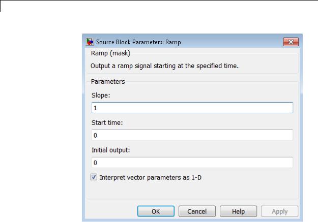
Ramp
Parameters and Dialog Box
Slope
Specify the rate of change of the generated signal. The default is 1.
Start time
Specify the time at which the block begins generating the signal. The default is 0.
Initial output
Specify the initial value of the output signal. The default is 0.
Interpret vector parameters as 1-D
If you select this option and the other parameters are one-row or one-column matrices, after scalar expansion, the block outputs a 1-D signal (vector). Otherwise, the output dimensionality is
2-1354

Ramp
the same as that of the other parameters. See “Determining the Output Dimensions of Source Blocks” in the Simulink documentation.
Examples The following Simulink examples show how to use the Ramp block:
• sldemo_VariableTransportDelay_pipe
Characteristics |
Sample Time |
Inherited from driven block |
|
Scalar Expansion |
Yes |
|
Dimensionalized |
Yes |
|
Zero-Crossing Detection |
Yes |
|
|
|
2-1355

Random Number
Purpose |
Generate normally distributed random numbers |
Library Sources
Description The Random Number block generates normally distributed random numbers. To generate uniformly distributed random numbers, use the Uniform Random Number block.
You can generate a repeatable sequence using any Random Number block with the same nonnegative seed and parameters. The seed resets to the specified value each time a simulation starts. By default, the block produces a sequence that has a mean of 0 and a variance of 1. To generate a vector of random numbers with the same mean and variance, specify the Seed parameter as a vector.
Avoid integrating a random signal, because solvers must integrate relatively smooth signals. Instead, use the Band-Limited White Noise block.
The numeric parameters of this block must have the same dimensions after scalar expansion. If you select the Interpret vector parameters as 1-D check box and the numeric parameters are row or column vectors after scalar expansion, the block outputs a 1-D signal. If you clear the
Interpret vector parameters as 1-D check box, the block outputs a signal of the same dimensionality as the parameters.
Data Type The Random Number block outputs a real signal of type double. For
Support more information, see “Data Types Supported by Simulink” in the Simulink documentation.
2-1356

Random Number
Parameters and Dialog Box
Mean
Specify the mean of the random numbers. The default is 0.
Variance
Specify the variance of the random numbers. The default is 1.
Seed
Specify the starting seed for the random number generator. The default is 0.
2-1357

Random Number
The seed must be 0 or a positive integer. Output is repeatable for a given seed.
Sample time
Specify the time interval between samples. The default is 0.1, which matches the default sample time of the Band-Limited White Noise block. See “Specify Sample Time” in the Simulink documentation for more information.
Interpret vector parameters as 1-D
If you select this check box and the other parameters are row or column vectors after scalar expansion, the block outputs a 1-D signal. Otherwise, the block outputs a signal of the same dimensionality as the other parameters. For more information, see “Determining the Output Dimensions of Source Blocks” in the Simulink documentation.
Characteristics |
|
Sample Time |
Specified in the Sample time |
|
|
|
parameter |
|
|
Scalar Expansion |
Yes, of parameters |
|
|
Dimensionalized |
Yes |
|
|
Multidimensionalized |
Yes |
|
|
Zero-Crossing Detection |
No |
See Also |
|
Uniform Random Number |
|
2-1358

Rate Limiter
Purpose |
Limit rate of change of signal |
Library Discontinuities
Description The Rate Limiter block limits the first derivative of the signal passing through it. The output changes no faster than the specified limit. The derivative is calculated using this equation:‘
rate = u(i) − y(i − 1) t(i) − t(i − 1)
u(i) and t(i) are the current block input and time, and y(i–1) and t(i–1) are the output and time at the previous step. The output is determined by comparing rate to the Rising slew rate and Falling slew rate parameters:
•If rate is greater than the Rising slew rate parameter (R), the output is calculated as
y(i) = t R + y(i − 1).
•If rate is less than the Falling slew rate parameter (F), the output is calculated as
y(i) = t F + y(i − 1).
•If rate is between the bounds of R and F, the change in output is equal to the change in input:
y(i) = u(i)
When the block is running in continuous mode (for example, Sample time mode is inherited and Sample time of the driving block is zero), the Initial condition is ignored. The block output at t = 0 is equal to the initial input:
2-1359

Rate Limiter
Data Type
Support
y(0) = u(0)
When the block is running in discrete mode (for example, Sample time mode is inherited and Sample time of the driving block is nonzero), the Initial condition is preserved:
y(−1) = Ic
where Ic is the initial condition. The block output at t = 0 is calculated as if rate is outside the bounds of R and F. For t = 0, rate is calculated as follows:
= u(0) − y(−1)
rate
sampletime
The Rate Limiter block accepts and outputs signals of any numeric data type that Simulink supports, except Boolean. The Rate Limiter block supports fixed-point data types.
For more information, see “Data Types Supported by Simulink” in the Simulink documentation.
2-1360

Rate Limiter
Parameters and Dialog Box
Rising slew rate
Specify the limit of the derivative of an increasing input signal. This parameter is tunable for fixed-point inputs.
Falling slew rate
Specify the limit of the derivative of a decreasing input signal. This parameter is tunable for fixed-point inputs.
Sample time mode
Specify the sample time mode, continuous or inherited from the driving block.
2-1361

Rate Limiter
Initial condition
Set the initial output of the simulation. Simulink software does not allow you to set the initial condition of this block to inf or NaN.
Treat as gain when linearizing
Linearization commands in Simulink software treat this block as a gain in state space. Select this check box to cause the linearization commands to treat the gain as 1; otherwise, the commands treat the gain as 0.
Characteristics |
|
Direct Feedthrough |
Yes |
|
|
Sample Time |
Continuous or inherited (specified in |
|
|
|
the Sample time mode parameter) |
|
|
Scalar Expansion |
Yes, of input and parameters |
|
|
Dimensionalized |
Yes |
|
|
Zero-Crossing Detection |
No |
See Also |
|
Rate Limiter Dynamic |
|
2-1362
Rate Limiter Dynamic
Purpose |
Limit rising and falling rates of signal |
Library Discontinuities
Description
Data Type
Support
The Rate Limiter Dynamic block limits the rising and falling rates of the signal.
•The external signal up sets the upper limit on the rising rate of the signal.
•The external signal lo sets the lower limit on the falling rate of the signal.
Follow these guidelines when using the Rate Limiter Dynamic block:
•Ensure that the data types of up and lo are the same as the data type of the input signal u.
When the lower limit uses a signed type and the input signal uses an unsigned type, the output signal keeps increasing regardless of the input and the limits.
•Use a fixed-step solver to simulate models that contain this block.
Because the Rate Limiter Dynamic block does not support continuous sample time, simulation with a variable-step solver causes an error.
The Rate Limiter Dynamic block accepts input signals of the following data types:
• Floating point
2-1363

Rate Limiter Dynamic
•Built-in integer
•Fixed point
The data type of the output signal Y matches the data type of the input signal u.
For more information, see “Data Types Supported by Simulink” in the Simulink documentation.
Parameters and Dialog Box
Characteristics
See Also
Direct Feedthrough |
Yes |
Scalar Expansion |
Yes |
|
|
Rate Limiter
2-1364

Rate Transition
Purpose |
Handle transfer of data between blocks operating at different rates |
|
||
Library |
Signal Attributes |
|
|
|
Description |
Transition Handling Options |
|
|
|
|
|
The Rate Transition block transfers data from the output of a block |
|
|
|
|
operating at one rate to the input of a block operating at a different |
|
|
|
|
rate. Use the block parameters to trade data integrity and deterministic |
|
|
|
|
transfer for faster response or lower memory requirements. To learn |
|
|
|
|
about data integrity and deterministic data transfer, see “Data Transfer |
|
|
|
|
Problems” in the Simulink Coder documentation. |
|
|
|
|
|
|
|
|
|
Transition Handling Options |
Block Parameter Settings |
|
|
|
• Data integrity |
Select: |
|
|
|
• Deterministic data transfer |
• Ensure data integrity |
|
|
|
• Maximum latency |
|
|
|
|
during data transfer |
|
|
|
|
|
• Ensure deterministic |
|
|
|
|
data transfer |
|
|
|
• Data integrity |
Select: |
|
|
|
• Nondeterministic data transfer |
• Ensure data integrity |
|
|
|
• Minimum latency |
|
|
|
|
during data transfer |
|
|
|
|
• Higher memory requirements |
Clear: |
|
|
|
|
|
|
|
|
|
• Ensure deterministic |
|
|
|
|
data transfer |
|
|
|
• Potential loss of data integrity |
Clear: |
|
|
|
• Nondeterministic data transfer |
• Ensure data integrity |
|
|
|
• Minimum latency |
|
|
|
|
during data transfer |
|
|
|
|
• Lower memory requirements |
• Ensure deterministic |
|
|
|
|
data transfer |
|
2-1365

Rate Transition
Dependencies
The behavior of the Rate Transition block depends on:
•Sample times of the ports to which the block connects (see “Effects of Synchronous Sample Times” on page 2-1367 and “Effects of Asynchronous Sample Times” on page 2-1369)
•Priorities of the tasks for the source and destination sample times (see “Sample time properties” in the Simulink documentation)
•Whether the model specifies a fixedor variable-step solver (see “Solvers” in the Simulink documentation)
Block Labels
When you update your diagram, a label appears on the Rate Transition block to indicate simulation behavior.
|
Label |
Block Behavior |
|
|
ZOH |
Acts as a zero-order hold |
|
|
1/z |
Acts as a unit delay |
|
|
Buf |
Copies input to output under semaphore control |
|
|
Db_buf |
Copies input to output using double buffers |
|
|
Copy |
Unprotected copy of input to output |
|
|
NoOp |
Does nothing |
|
|
Mixed |
Expands to multiple blocks with different behaviors |
|
|
|
|
|
2-1366

Rate Transition
The block behavior label shows the method that ensures safe transfer of data between tasks operating at different rates. You can use the sample-time colors feature (see “View Sample Time Information” in the Simulink documentation) to display the relative rates that the block bridges. Consider, for example, the following model:
Sample-time colors and the block behavior label show that the Rate Transition block at the top of the diagram acts as a zero-order hold in a fast-to-slow transition and the bottom Rate Transition block acts as a unit delay in a slow-to-fast transition.
For more information, see “Handle Rate Transitions” in the Simulink Coder documentation.
Effects of Synchronous Sample Times
The following table summarizes how each label appears if the sample times of the input and output ports (inTs and outTs) are periodic, or synchronous.
2-1367

Rate Transition
Block Settings |
Block Label |
|
|
||
Rate |
Conditions for Rate |
With Data |
With |
Without |
|
Transition |
Transition Block |
Integrity and |
Only |
Data |
|
|
|
Determinism |
Data |
Integrity or |
|
|
|
|
Integrity |
Determinism |
|
inTs = |
inTsOffset < outTsOffset |
None (error) |
Buf |
Copy or NoOp |
|
outTs |
|
|
|
(see note that |
|
inTsOffset = outTsOffset |
Copy or NoOp |
Copy or |
|||
|
follows the |
||||
(Equal) |
|
(see note that |
NoOp (see |
||
|
table) |
||||
|
|
follows the |
note that |
||
|
|
|
|||
|
|
table) |
follows |
|
|
|
|
|
the table) |
|
|
|
inTsOffset > outTsOffset |
None (error) |
Db_buf |
|
|
inTs < |
inTs = outTs / N |
ZOH |
Buf |
|
|
outTs |
inTsOffset, outTsOffset = 0 |
|
|
|
|
(Fast to |
|
|
|
||
inTs = outTs / N |
None (error) |
|
|
||
slow) |
|
|
|||
inTsOffset ≤ outTsOffset |
|
|
|
||
|
|
|
|
||
|
inTs = outTs / N |
None (error) |
Db_buf |
|
|
|
inTsOffset > outTsOffset |
|
|
|
|
|
inTs ≠ outTs / N |
None (error) |
|
|
|
inTs > |
inTs = outTs * N |
1/z |
Db_buf |
|
|
outTs |
inTsOffset, outTsOffset = 0 |
|
|
|
|
(Slow to |
|
|
|
||
inTs = outTs * N |
None (error) |
|
|
||
fast) |
|
|
|||
inTsOffset ≤ outTsOffset |
|
|
|
||
|
|
|
|
||
|
inTs = outTs * N |
None (error) |
|
|
|
|
inTsOffset > outTsOffset |
|
|
|
|
|
inTs ≠ outTs * N |
None (error) |
|
|
|
KEY |
|
|
|
|
|
|
|
|
|
|
|
2-1368

Rate Transition
Block Settings |
Block Label |
|
|
|
Rate |
Conditions for Rate |
With Data |
With |
Without |
Transition |
Transition Block |
Integrity and |
Only |
Data |
|
|
Determinism |
Data |
Integrity or |
|
|
|
Integrity |
Determinism |
|
|
|
|
|
•inTs, outTs: Sample times of input and output ports, respectively
•inTsOffset, outTsOffset: Sample time offsets of input and output ports, respectively
•N: Integer value > 1
When you select Block reduction in the Optimization pane of the Configuration Parameters dialog box, Copy reduces to NoOp. No code generation occurs for a Rate Transition block with a NoOp label. To prevent a block from being reduced when block reduction is on, add a test point to the block output (see “Test Points” in the Simulink documentation).
Effects of Asynchronous Sample Times
The following table summarizes how each label appears if the sample time of the input or output port (inTs or outTs) is not periodic, or asynchronous.
|
Block Settings |
Block Label |
|
|
|
|
|
With Data |
With Only |
Without Data |
|
|
|
Integrity |
Data |
Integrity or |
|
|
|
and |
Integrity |
Determinism |
|
|
|
Determinism |
|
|
|
|
inTs = outTs |
Copy |
Copy |
Copy |
|
|
inTs ≠ outTs |
None (error) |
Db_buf |
|
|
|
KEY |
|
|
|
|
• inTs, outTs: Sample times of input and output ports, respectively
2-1369

Rate Transition
Data Type
Support
The Rate Transition block accepts signals of any data type that Simulink supports, including fixed-point and enumerated data types.
For more information, see “Data Types Supported by Simulink” in the Simulink documentation.
2-1370

Rate Transition
Parameters
2-1371

Rate Transition
and Dialog Box
Ensure data integrity during data transfer
Selecting this check box results in generated code that ensures data integrity when the block transfers data. If you select this check box and the transfer is nondeterministic (see Ensure deterministic data transfer below), the generated code uses double-buffering to prevent the fast block from interrupting the data transfer. Otherwise, the generated code uses a copy
operation to effect the data transfer. The copy operation consumes less memory than double-buffering but is also interruptible, which can lead to loss of data during nondeterministic data transfers.
Select this check box if you want the generated code to operate with maximum responsiveness (i.e., nondeterministically) and data integrity. For more information, see “Rate Transition Block Options” in the Simulink Coder documentation.
Ensure deterministic data transfer (maximum delay)
Selecting this check box results in generated code that transfers data at the sample rate of the slower block, that is, deterministically. If you do not select this check box, data transfers occur as soon as new data is available from the source block and the receiving block is ready to receive the data. You avoid transfer delays, thus ensuring that the system operates with maximum responsiveness. However, transfers can occur unpredictably, which is undesirable in some applications. For more information, see “Rate Transition Block Options” in the Simulink Coder documentation.
Initial conditions
This parameter applies only to slow-to-fast transitions. It specifies the initial output of the Rate Transition block at the beginning of a transition when there is no output from the slow block connected to the input of the Rate Transition block. Simulink does not allow the initial output of this block to be Inf or NaN.
Output port sample time options
Specifies a mode for setting the output port sample time. The options are:
2-1372
Rate Transition
Bus
Support
•Specify — Allows you to use the Output port sample time parameter to specify the output rate to which the Rate Transition block converts its input rate.
•Inherit — Specifies that the Rate Transition block inherits an output rate from the block to which the output port is connected.
•Multiple of input port sample time — Allows you to use the Sample time multiple (>0) parameter to specify the Rate Transition block output rate as a multiple of its input rate.
If you specify Inherit and all blocks connected to the output port also inherit sample time, the fastest sample time in the model applies.
Output port sample time
This parameter is visible when you set Output port sample time options to Specify. Enter a value that specifies the output rate to which the block converts its input rate. The default value (-1) specifies that the Rate Transition block inherits the output rate from the block to which the output port is connected. See “Specify Sample Time” in the Simulink documentation for information on how to specify the output rate.
Sample time multiple (>0)
This parameter is visible when you set Output port sample time options to Multiple of input port sample time. Enter a positive value that specifies the output rate as a multiple of the input port sample time. The default value (1) specifies that the output rate is the same as the input rate. A value of 0.5 specifies that the output rate is half of the input rate, while a value of 2 specifies that the output rate is twice the input rate.
The Rate Transition block is a bus-capable block. The input can be a virtual or nonvirtual bus signal, with the restriction that Initial conditions must be zero, a nonzero scalar, or a finite numeric structure. For information about specifying an initial condition structure, see “Specify Initial Conditions for Bus Signals”.
2-1373

Rate Transition
All signals in a nonvirtual bus input to a Rate Transition block must have the same sample time, even if the elements of the associated bus object specify inherited sample times. You can use a Rate Transition block to change the sample time of an individual signal, or of all signals in a bus. See “About Composite Signals” and “Bus-Capable Blocks” in the Simulink documentation for more information.
You can use an array of buses as an input signal to a Rate Transition block. For details about defining and using an array of buses, see “Combine Buses into an Array of Buses”.
Characteristics |
Bus-capable |
Yes, with restrictions as noted |
|
|
above. |
|
Direct Feedthrough |
No, for slow-to-fast transitions for |
|
|
which you select the Ensure data |
|
|
integrity during data transfer |
|
|
check box. Yes, otherwise. |
|
Sample Time |
This block supports |
|
|
discrete-to-discrete transitions. |
|
Scalar Expansion |
Yes, of input. |
|
Dimensionalized |
Yes |
|
Multidimensionalized |
Yes |
|
Zero-Crossing Detection |
No |
|
|
|
2-1374

Real-Imag to Complex
Purpose |
Convert real and/or imaginary inputs to complex signal |
Library |
Math Operations |
Description |
The Real-Imag to Complex block converts real and/or imaginary inputs |
|
to a complex-valued output signal. |
|
The inputs can both be arrays (vectors or matrices) of equal dimensions, |
|
or one input can be an array and the other a scalar. If the block has an |
|
array input, the output is a complex array of the same dimensions. The |
|
elements of the real input map to the real parts of the corresponding |
|
complex output elements. The imaginary input similarly maps to the |
|
imaginary parts of the complex output signals. If one input is a scalar, |
|
it maps to the corresponding component (real or imaginary) of all the |
|
complex output signals. |
Data Type The block accepts input signals of the following data types:
Support
•Floating point
•Built-in integer
•Fixed point
Complex fixed-point signals must have trivial slope and zero bias. For more information about support for fixed-point data types, see “Scaling” in the Simulink Fixed Point documentation.
2-1375

Real-Imag to Complex
Parameters and Dialog Box
Input
Specify the kind of input: a real input, an imaginary input, or both.
Real (Imag) part
This parameter appears only when you set Input to Real or Imag. If the input is a real-part signal, this parameter specifies the constant imaginary part of the output signal. If the input is the imaginary part, this parameter specifies the constant real part of the output signal. The title of this parameter changes to reflect its usage.
2-1376

Real-Imag to Complex
Sample time (-1 for inherited)
Specify the time interval between samples. To inherit the sample time, set this parameter to -1. See “Specify Sample Time” in the online documentation for more information.
Characteristics |
|
Direct Feedthrough |
Yes |
|
|
Sample Time |
Inherited from driving block |
|
|
Scalar Expansion |
Yes, of the input when the function |
|
|
|
requires two inputs |
|
|
Dimensionalized |
Yes |
|
|
Multidimensionalized |
Yes |
|
|
Zero-Crossing Detection |
No |
See Also |
|
Complex to Real-Imag |
|
2-1377

Relational Operator
Purpose |
Perform specified relational operation on inputs |
|
|
Library |
Logic and Bit Operations |
|
|
Description |
Two-Input Mode |
|
|
|
By default, the Relational Operator block compares two inputs using |
|
|
|
the Relational operator parameter that you specify. The first input |
|
|
|
corresponds to the top input port and the second input to the bottom |
|
|
|
input port. (See “How to Rotate a Block” in the Simulink documentation |
|
|
|
for a description of the port order for various block orientations.) |
|
|
|
You can specify one of the following operations in two-input mode: |
|
|
|
|
|
|
|
Operation |
Description |
|
|
== |
TRUE if the first input is equal to the second input |
|
|
~= |
TRUE if the first input is not equal to the second input |
|
|
< |
TRUE if the first input is less than the second input |
|
|
<= |
TRUE if the first input is less than or equal to the |
|
|
|
second input |
|
|
>= |
TRUE if the first input is greater than or equal to the |
|
|
|
second input |
|
|
> |
TRUE if the first input is greater than the second input |
|
|
|
|
|
2-1378

Relational Operator
You can specify inputs as scalars, arrays, or a combination of a scalar and an array.
|
For... |
The output is... |
|
|
Scalar inputs |
A scalar |
|
|
Array inputs |
An array of the same dimensions, where each |
|
|
|
element is the result of an element-by-element |
|
|
|
comparison of the input arrays |
|
|
Mixed scalar and |
An array, where each element is the result |
|
|
array inputs |
of a comparison between the scalar and the |
|
|
|
corresponding array element |
|
The input with the smaller positive range is converted to the data type of the other input offline using round-to-nearest and saturation. This conversion occurs before the comparison.
You can specify the output data type using the Output data type parameter. The output equals 1 for TRUE and 0 for FALSE.
Tip Select an output data type that represents zero exactly. Data types that satisfy this condition include signed and unsigned integers and any floating-point data type.
One-Input Mode
When you select one of the following operations for Relational operator, the block switches to one-input mode.
Operation Description
isInf TRUE if the input is Inf
isNaN TRUE if the input is NaN
isFinite TRUE if the input is finite
2-1379

Relational Operator
Data Type
Support
For an input that is not floating point, the block produces the following output.
Data Type |
Operation |
Block Output |
|
• Fixed |
isInf |
FALSE |
|
point |
|
|
|
isNaN |
FALSE |
||
|
|||
|
|
|
|
• Boolean |
isFinite |
TRUE |
|
• Built-in |
|||
|
|
||
integer |
|
|
|
|
|
|
Rules for Data Type Propagation
The following rules apply for data type propagation when your block has one or more input ports with unspecified data types.
|
When the block is |
And... |
The block uses... |
|
|
in... |
|
|
|
|
Two-input mode |
Both input ports |
double as the default |
|
|
|
have unspecified data |
data type for both |
|
|
|
types |
inputs |
|
|
|
One input port has an |
The data type from |
|
|
|
unspecified data type |
the specified input |
|
|
|
|
port as the default |
|
|
|
|
data type of the other |
|
|
|
|
port |
|
|
One-input mode |
The input port has an |
double as the default |
|
|
|
unspecified data type |
data type for the |
|
|
|
|
input |
|
The Relational Operator block accepts real or complex signals of any data type that Simulink supports, including fixed-point and enumerated data types. For two-input mode, one input can be real and the other complex when the operator is == or ~=. Complex inputs work only for
==, ~=, isInf, isNaN, and isFinite.
2-1380

Relational Operator
|
For more information, see “Data Types Supported by Simulink” in the |
|
Simulink documentation. |
Parameters |
The Main pane of the Relational Operator block dialog box appears |
and |
as follows: |
Dialog |
|
Box |
|
2-1381

Relational Operator
The Data Type pane of the Relational Operator block dialog box appears as follows:
2-1382
Relational Operator
Show data type assistant
Display the Data Type Assistant.
Settings
The Data Type Assistant helps you set the Output data type parameter.
For more information, see “Specify Block Output Data Types”.
Command-Line Information
See “Block-Specific Parameters” on page 8-109 for the command-line information.
2-1383

Relational Operator
Relational operator
Specify the operation for comparing two inputs or determining the signal type of one input.
Settings
Default: <=
==
TRUE if the first input is equal to the second input
~=
TRUE if the first input is not equal to the second input
<
TRUE if the first input is less than the second input
<=
TRUE if the first input is less than or equal to the second input
>=
TRUE if the first input is greater than or equal to the second input
>
TRUE if the first input is greater than the second input
isInf
TRUE if the input is Inf
isNaN
TRUE if the input is NaN
isFinite
TRUE if the input is finite
Command-Line Information
See “Block-Specific Parameters” on page 8-109 for the command-line information.
2-1384

Relational Operator
Enable zero-crossing detection
Select to enable zero-crossing detection. For more information, see “Zero-Crossing Detection” in the Simulink documentation.
Settings
Default: On
 On
On
Enable zero-crossing detection.
 Off
Off
Do not enable zero-crossing detection.
Command-Line Information
See “Block-Specific Parameters” on page 8-109 for the command-line information.
2-1385

Relational Operator
Sample time (-1 for inherited)
Enter the discrete interval between sample time hits or specify another appropriate sample time such as continuous or inherited.
Settings
Default: -1
By default, the block inherits its sample time based upon the context of the block within the model. To set a different sample time, enter a valid sample time based upon the table in “Types of Sample Time”.
See also “Specify Sample Time” in the online documentation for more information.
Command-Line Information
See “Block-Specific Parameters” on page 8-109 for the command-line information.
2-1386

Relational Operator
Require all inputs to have the same data type
Require that all inputs have the same data type.
Settings
Default: Off
 On
On
Require that all inputs have the same data type.
 Off
Off
Do not require that all inputs have the same data type.
Dependency
This check box is not available when you select isInf, isNaN, or isFinite for Relational operator, because the block is in one-input mode.
Command-Line Information
See “Block-Specific Parameters” on page 8-109 for the command-line information.
2-1387

Relational Operator
Output data type
Specify the output data type.
Settings
Default: boolean
Inherit: Logical (see Configuration Parameters:
Optimization)
Uses the Implement logic signals as Boolean data configuration parameter (see “Implement logic signals as Boolean data (vs. double)”) to specify the output data type.
Note This option supports models created before the boolean option was available. Use one of the other options, preferably boolean, for new models.
boolean
Specifies output data type is boolean.
fixdt(1,16)
Specifies output data type is fixdt(1,16).
<data type expression>
Uses the name of a data type object, for example,
Simulink.NumericType.
Tip To enter a built-in data type (double, single, int8, uint8, int16, uint16, int32, or uint32), enclose the expression in single quotes. For example, enter 'double' instead of double.
Command-Line Information
See “Block-Specific Parameters” on page 8-109 for the command-line information.
2-1388

Relational Operator
Mode
Select the category of data to specify.
Settings
Default: Built in
Inherit
Specifies inheritance rules for data types. Selecting Inherit
enables Logical (see Configuration Parameters:
Optimization).
Built in
Specifies built-in data types. Selecting Built in enables boolean.
Fixed point
Specifies fixed-point data types.
Expression
Specifies expressions that evaluate to data types.
Dependency
Clicking the Show data type assistant button enables this parameter.
Command-Line Information
See “Block-Specific Parameters” on page 8-109 for the command-line information.
See Also
See “Specify Data Types Using Data Type Assistant”.
2-1389

Relational Operator
Data type override
Specify data type override mode for this signal.
Settings
Default: Inherit
Inherit
Inherits the data type override setting from its context, that is, from the block, Simulink.Signal object or Stateflow chart in Simulink that is using the signal.
Off
Ignores the data type override setting of its context and uses the fixed-point data type specified for the signal.
Tip
The ability to turn off data type override for an individual data type provides greater control over the data types in your model when you apply data type override. For example, you can use this option to ensure that data types meet the requirements of downstream blocks regardless of the data type override setting.
Dependency
This parameter appears only when the Mode is Built in or Fixed point.
2-1390

Relational Operator
Signedness
Specify whether you want the fixed-point data as signed or unsigned.
Settings
Default: Signed
Signed
Specify the fixed-point data as signed.
Unsigned
Specify the fixed-point data as unsigned.
Dependencies
Selecting Mode > Fixed point enables this parameter.
Command-Line Information
See “Block-Specific Parameters” on page 8-109 for the command-line information.
See Also
For more information, see “Specifying a Fixed-Point Data Type”.
2-1391

Relational Operator
Word length
Specify the bit size of the word that holds the quantized integer.
Settings
Default: 16
Minimum: 0
Maximum: 32
Dependencies
Selecting Mode > Fixed point enables this parameter.
Command-Line Information
See “Block-Specific Parameters” on page 8-109 for the command-line information.
See Also
For more information, see “Specifying a Fixed-Point Data Type”.
2-1392
Relational Operator
Scaling
Specify the method for scaling your fixed-point data to avoid overflow conditions and minimize quantization errors.
Settings
Default: Integer
Integer
Specify integer. This setting has the same result as specifying a binary point location and setting fraction length to 0.
Command-Line Information
See “Block-Specific Parameters” on page 8-109 for the command-line information.
See Also
See “Specifying a Fixed-Point Data Type”.
2-1393

Relational Operator
Examples
In the sldemo_fuelsys model, the fuel_rate_control/airflow_calc subsystem uses two Relational Operator blocks:
Both Relational Operator blocks operate in two-input mode.
|
The block that uses this |
Compares... |
|
|
operator... |
|
|
|
<= |
The value of the oxygen sensor to |
|
|
|
the threshold value, 0.5 |
|
|
== |
The value of the fuel mode to the |
|
|
|
ideal value, sld_FuelModes.LOW |
|
2-1394

Relational Operator
Characteristics |
Direct Feedthrough |
Yes |
|
Sample Time |
Specified in the Sample time |
|
|
parameter |
|
Scalar Expansion |
Yes, of inputs |
|
Dimensionalized |
Yes |
|
Multidimensionalized |
Yes |
|
Zero-Crossing Detection |
Yes, if enabled |
|
|
|
2-1395

Relay
Purpose |
Switch output between two constants |
Library Discontinuities
Description The Relay block allows its output to switch between two specified values. When the relay is on, it remains on until the input drops below the value of the Switch off point parameter. When the relay is off, it remains off until the input exceeds the value of the Switch on point parameter. The block accepts one input and generates one output.
The Switch on point value must be greater than or equal to the Switch off point. Specifying a Switch on point value greater than the Switch off point models hysteresis, whereas specifying equal values models a switch with a threshold at that value.
Note When the initial input falls between the Switch off point and Switch on point values, the initial output is the value when the relay is off.
Data Type The Relay block accepts signals of the following data types:
Support
•Floating point
•Built-in integer
•Fixed point
•Boolean
•Enumerated (output only)
If Output when on or Output when off is an enumerated value, both must be of the same enumerated type as the output.
For more information, see “Data Types Supported by Simulink” in the Simulink documentation.
2-1396

Relay
Parameters The Main pane of the Relay block dialog box appears as follows:
and Dialog Box
2-1397

Relay
Switch on point
The “on” threshold for the relay. The Switch on point parameter is converted to the input data type offline using round-to-nearest and saturation.
Switch off point
The “off” threshold for the relay. The Switch off point parameter is converted to the input data type offline using round-to-nearest and saturation.
Output when on
The output when the relay is on.
Output when off
The output when the relay is off.
Input processing
Specify whether the block performs sampleor frame-based processing. You can select one of the following options:
•Elements as channels (sample based) — Treat each element of the input as a separate channel (sample-based processing).
•Columns as channels (frame based) — Treat each column of the input as a separate channel (frame-based processing).
Note Frame-based processing requires a DSP System Toolbox license.
For more information, see “Sampleand Frame-Based Concepts” in the DSP System Toolbox documentation.
•Inherited — Inherit the processing mode from the input signal and delay the input accordingly. You can identify whether the input signal is sample or frame based by looking at the signal line. Simulink represents sample-based signals with a single line and frame-based signals with a double line.
2-1398

Relay
Note When you choose the Inherited option for the Input processing parameter, and the input signal is frame-based, Simulink® will generate a warning or error in future releases.
Use Input processing to specify whether the block performs sampleor frame-based processing. The block accepts frame-based signals for the input u. All other input signals must be sample based.
|
Input Signal u |
Input Processing |
Block Works? |
|
|
|
Mode |
|
|
|
Sample based |
Sample based |
Yes |
|
|
Frame based |
|
No, produces an |
|
|
|
|
error |
|
|
Sample based |
Frame based |
Yes |
|
|
Frame based |
|
Yes |
|
|
Sample based |
Inherited |
Yes |
|
|
Frame based |
|
Yes |
|
|
|
|
|
|
For more information about these two processing modes, see “Sampleand Frame-Based Concepts” in the DSP System Toolbox documentation.
Enable zero-crossing detection
Select to enable zero-crossing detection. For more information, see “Zero-Crossing Detection” in the Simulink documentation.
Sample time (-1 for inherited)
Specify the time interval between samples. To inherit the sample time, set this parameter to -1. See “Specify Sample Time” in the Simulink documentation for more information.
2-1399

Relay
The Signal Attributes pane of the Relay block dialog box appears as follows:
2-1400

Relay
Output minimum
Specify the minimum value that the block should output. The default value is [] (unspecified). Simulink software uses this value to perform:
•Parameter range checking (see “Check Parameter Values”)
•Simulation range checking (see “Signal Ranges”)
•Automatic scaling of fixed-point data types
Output maximum
Specify the maximum value that the block should output. The default value is [] (unspecified). Simulink software uses this value to perform:
•Parameter range checking (see “Check Parameter Values”)
•Simulation range checking (see “Signal Ranges”)
•Automatic scaling of fixed-point data types
Output data type
Specify the output data type. You can set it to:
•A rule that inherits a data type, for example, Inherit: Inherit via back propagation
•The name of a built-in data type, for example, single
•The name of a data type object, for example, a
Simulink.NumericType object
•An expression that evaluates to a data type, for example, fixdt(1,16,0)
•An enumerated data type, for example, Enum:BasicColors
In this case, Output when on and Output when off must be of the same enumerated type.
2-1401

Relay
Click the Show data type assistant button  to display the Data Type Assistant, which helps you set the
Output data type parameter.
See “Specify Block Output Data Types” in Simulink User’s Guide for more information.
Lock output data type setting against changes by the fixed-point tools
Select to lock the output data type setting of this block against changes by the Fixed-Point Tool and the Fixed-Point Advisor. For more information, see “Use Lock Output Data Type Setting”.
Examples The sldemo_househeat model shows how you can use the Relay block. The Relay block appears in the Thermostat subsystem.
The thermostat allows fluctuations of 5 degrees Fahrenheit above or below the desired room temperature. If air temperature drops below 65 degrees Fahrenheit, the thermostat turns on the heater. The Relay block outputs a value of 1 to turn on the heater and a value of 0 to turn off the heater.
Characteristics |
Direct Feedthrough |
Yes |
|
Sample Time |
Specified in the Sample time |
|
|
parameter |
|
Scalar Expansion |
Yes |
|
Dimensionalized |
Yes |
|
|
|
2-1402
Relay
Multidimensionalized |
No |
Zero-Crossing Detection |
Yes, if enabled |
|
|
2-1403

Repeating Sequence
Purpose |
Generate arbitrarily shaped periodic signal |
Library |
Sources |
Description |
The Repeating Sequence block outputs a periodic scalar signal having |
|
a waveform that you specify using the Time values and Output |
|
values parameters. The Time values parameter specifies a vector |
|
of output times. The Output values parameter specifies a vector of |
|
signal amplitudes at the corresponding output times. Together, the |
|
two parameters specify a sampling of the output waveform at points |
|
measured from the beginning of the interval over which the waveform |
|
repeats (the period of the signal). |
|
By default, both parameters are [0 2]. These default settings specify a |
|
sawtooth waveform that repeats every 2 seconds from the start of the |
|
simulation and has a maximum amplitude of 2. |
Algorithm |
The block sets the input period as the difference between the first and |
|
last value of the Time values parameter. The output at any time t |
|
is the output at time t = t-n*period, where n is an integer. The |
|
sequence repeats at t = n*period. The block uses linear interpolation |
|
to compute the value of the waveform between the output times that |
|
you specify. |
|
In the following model, the Repeating Sequence block defines Time |
|
values as [0:0.1:0.5] and Output values as [0 15 25 09 13 17]. The stop |
|
time of the simulation is 0.7 second. |
For the Repeating Sequence block:
• The input period is 0.5.
2-1404

Repeating Sequence
•The output at any time t is the output at time t = t-0.5n, where n = 0, 1, 2, and so on.
•The sequence repeats at t = 0.5n, where n = 0, 1, 2, and so on.
When you run the model, you get the following results:
At t = 0.5, the expected output is equal to the output at t = 0, which is 0. Therefore, the last value in the Output values vector [0 15 25 09 13 17] does not appear.
2-1405
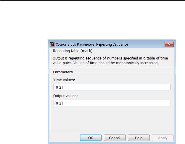
Repeating Sequence
Data Type
Support
Parameters and Dialog Box
The Repeating Sequence block outputs real signals of type double.
For more information, see “Data Types Supported by Simulink” in the Simulink documentation.
Time values
Specify a vector of monotonically increasing time values. The default is [0 2].
Output values
Specify a vector of output values. Each element corresponds to the time value in the same column. The default is [0 2].
2-1406

Repeating Sequence
Examples |
The following Simulink examples show how to use the Repeating |
||
|
|
Sequence block: |
|
|
|
• sldemo_fuelsys |
|
|
|
• sldemo_hydrod |
|
|
|
• sldemo_VariableTransportDelay |
|
Characteristics |
|
|
|
|
Sample Time |
Continuous |
|
|
|
Scalar Expansion |
No |
|
|
Dimensionalized |
No |
|
|
Zero-Crossing Detection |
No |
See Also |
|
Repeating Sequence Interpolated, Repeating Sequence Stair |
|
2-1407

Repeating Sequence Interpolated
Purpose |
Output discrete-time sequence and repeat, interpolating between data |
|
points |
Library |
Sources |
Description |
The Repeating Sequence Interpolated block outputs a discrete-time |
|
sequence and then repeats it. Between data points, the block uses the |
|
method you specify for the Lookup Method parameter to determine |
|
the output. |
Data Type |
The Repeating Sequence Interpolated block outputs signals of the |
Support |
following data types: |
|
• Floating point |
|
• Built-in integer |
|
• Fixed point |
|
• Boolean |
|
For more information, see “Data Types Supported by Simulink” in the |
|
Simulink documentation. |
2-1408

Repeating Sequence Interpolated
Parameters |
The Main pane of the Repeating Sequence Interpolated block dialog box |
and |
appears as follows: |
Dialog |
|
Box |
|
Vector of output values
Specify the column vector containing output values of the discrete time sequence.
Vector of time values
Specify the column vector containing time values. The time values must be strictly increasing, and the vector must have the same size as the vector of output values.
2-1409

Repeating Sequence Interpolated
Lookup Method
Specify the lookup method to determine the output between data points.
Sample time
Specify the time interval between samples. To inherit the sample time, set this parameter to -1. See “Specify Sample Time” for more information.
The Signal Attributes pane of the Repeating Sequence Interpolated block dialog box appears as follows:
2-1410

Repeating Sequence Interpolated
Output minimum
Specify the minimum value that the block should output. The default value is [] (unspecified). Simulink software uses this value to perform:
•Parameter range checking (see “Check Parameter Values”)
•Simulation range checking (see “Signal Ranges”)
•Automatic scaling of fixed-point data types
Output maximum
Specify the maximum value that the block should output. The default value is [] (unspecified). Simulink software uses this value to perform:
•Parameter range checking (see “Check Parameter Values”)
•Simulation range checking (see “Signal Ranges”)
•Automatic scaling of fixed-point data types
Output data type
Specify the output data type. You can set it to:
•A rule that inherits a data type, for example, Inherit: Inherit via back propagation
•The name of a built-in data type, for example, single
•The name of a data type object, for example, a
Simulink.NumericType object
•An expression that evaluates to a data type, for example, fixdt(1,16,0)
Click the Show data type assistant button  to display the Data Type Assistant, which helps you set the
Output data type parameter.
See “Specify Block Output Data Types” for more information.
2-1411

Repeating Sequence Interpolated
Lock output data type setting against changes by the fixed-point tools
Select to lock the output data type setting of this block against changes by the Fixed-Point Tool and the Fixed-Point Advisor. For more information, see “Use Lock Output Data Type Setting”.
Characteristics
See Also
Sample Time |
Specified in the Sample time |
|
parameter |
|
|
Scalar Expansion |
Yes |
Zero-Crossing Detection |
No |
|
|
Repeating Sequence, Repeating Sequence Stair
2-1412
Repeating Sequence Stair
Purpose |
Output and repeat discrete time sequence |
Library Sources
Description The Repeating Sequence Stair block outputs and repeats a stair sequence that you specify with the Vector of output values parameter. For example, you can specify the vector as [3 1 2 4 1]', which produces the following stair sequence:
2-1413

Repeating Sequence Stair
Data Type
Support
The Repeating Sequence Stair block outputs signals of the following data types:
•Floating point
•Built-in integer
•Fixed point
•Boolean
•Enumerated
For more information, see “Data Types Supported by Simulink” in the Simulink documentation.
2-1414

Repeating Sequence Stair
Parameters |
The Main pane of the Repeating Sequence Stair block dialog box |
and |
appears as follows: |
Dialog |
|
Box |
|
Vector of output values
Specify the vector containing values of the repeating stair sequence.
Sample time
Specify the time interval between samples. To inherit the sample time, set this parameter to -1. See “Specify Sample Time” for more information.
The Signal Attributes pane of the Repeating Sequence Stair block dialog box appears as follows:
2-1415

Repeating Sequence Stair
Output minimum
Specify the minimum value that the block should output. The default value is [] (unspecified). Simulink software uses this value to perform:
•Parameter range checking (see “Check Parameter Values”)
•Simulation range checking (see “Signal Ranges”)
•Automatic scaling of fixed-point data types
Output maximum
Specify the maximum value that the block should output. The default value is [] (unspecified). Simulink software uses this value to perform:
2-1416

Repeating Sequence Stair
•Parameter range checking (see “Check Parameter Values”)
•Simulation range checking (see “Signal Ranges”)
•Automatic scaling of fixed-point data types
Output data type
Specify the output data type. You can set it to:
•A rule that inherits a data type, for example, Inherit: Inherit via back propagation
•The name of a built-in data type, for example, single
•The name of a data type object, for example, a
Simulink.NumericType object
•An expression that evaluates to a data type, for example, fixdt(1,16,0)
Click the Show data type assistant button  to display the Data Type Assistant, which helps you set the
Output data type parameter.
See “Specify Block Output Data Types” in the Simulink User’s Guide for more information.
Lock output data type setting against changes by the fixed-point tools
Select to lock the output data type setting of this block against changes by the Fixed-Point Tool and the Fixed-Point Advisor. For more information, see “Use Lock Output Data Type Setting”.
Characteristics |
Sample Time |
Specified in the Sample time |
|
|
parameter |
|
Scalar Expansion |
No |
|
Zero-Crossing Detection |
No |
|
|
|
2-1417

Repeating Sequence Stair
See Also |
Repeating Sequence, Repeating Sequence Interpolated |
2-1418

Resettable Delay
Purpose
Library
Description
See Also
Delay input signal by variable sample period and reset with external signal
Discrete
The Resettable Delay block is a variant of the Delay block that has the source of the initial condition set to Input port and the external reset algorithm set to Rising, by default.
•Delay
•Variable Integer Delay
2-1419

Reshape
Purpose
Library
Description
Change dimensionality of signal
Math Operations
The Reshape block changes the dimensionality of the input signal to a dimensionality that you specify, using the block’s Output dimensionality parameter. For example, you can use the block to change an N-element vector to a 1-by-N or N-by-1 matrix signal, and vice versa.
The Output dimensionality parameter lets you select any of the following output options.
|
Output |
|
|
|
Dimensionality |
Description |
|
|
1-D array |
Converts a multidimensional array to a vector |
|
|
|
(1-D array) array signal. The output vector |
|
|
|
consists of the first column of the input matrix |
|
|
|
followed by the second column, etc. (This |
|
|
|
option leaves a vector input unchanged.) |
|
|
Column vector |
Converts a vector, matrix, or |
|
|
|
multidimensional input signal to a |
|
|
|
column matrix, i.e., an M-by-1 matrix, where |
|
|
|
M is the number of elements in the input |
|
|
|
signal. For matrices, the conversion is done in |
|
|
|
column-major order. For multidimensional |
|
|
|
arrays, the conversion is done along the first |
|
|
|
dimension. |
|
2-1420

Reshape
|
Output |
|
|
|
Dimensionality |
Description |
|
|
Row vector |
Converts a vector, matrix, or |
|
|
|
multidimensional input signal to a row |
|
|
|
matrix, i.e., a 1-by-N matrix where N is |
|
|
|
the number of elements in the input signal. |
|
|
|
For matrices, the conversion is done in |
|
|
|
column-major order. For multidimensional |
|
|
|
arrays, the conversion is done along the first |
|
|
|
dimension. |
|
|
Customize |
Converts the input signal to an output signal |
|
|
|
whose dimensions you specify, using the |
|
|
|
Output dimensions parameter. The value |
|
|
|
of the Output dimensions parameter can |
|
|
|
be a oneor multi-element vector. A value |
|
|
|
of [N] outputs a vector of size N. A value |
|
|
|
of [M N] outputs an M-by-N matrix. The |
|
|
|
number of elements of the input signal must |
|
|
|
match the number of elements specified by |
|
|
|
the Output dimensions parameter. For |
|
|
|
multidimensional arrays, the conversion is |
|
|
|
done along the first dimension. |
|
|
Derive from reference |
Creates a second input port, Ref, on the block. |
|
|
input port |
Derives the dimensions of the output signal |
|
|
|
from the dimensions of the signal input to the |
|
|
|
Ref input port. Selecting this option disables |
|
|
|
the Output dimensions parameter. When |
|
|
|
you select this parameter, the input signals |
|
|
|
for both inport ports, U and Ref, must have |
|
|
|
the same sampling mode (sample-based or |
|
|
|
frame-based). |
|
2-1421

Reshape
Data Type
Support
The Reshape block accepts and outputs signals of any data type that Simulink supports, including fixed-point and enumerated data types.
For more information, see “Data Types Supported by Simulink” in the Simulink documentation.
You can use an array of buses as an input signal to a Reshape block. For details about defining and using an array of buses, see “Combine Buses into an Array of Buses”.
2-1422
Reshape
Parameters and
Dialog |
Output dimensionality |
|
Box |
Specify the dimensionality of the output signal. |
|
Output dimensions |
|
|
|
|
|
|
Specify a custom output dimensionality. This parameter |
|
|
is available only when you set Output dimensionality to |
|
|
Customize. |
|
Characteristics |
|
|
Direct Feedthrough |
Yes |
|
|
Sample Time |
Inherited from driving block |
|
|
|
2-1423

Reshape
Scalar Expansion |
N/A |
Dimensionalized |
Yes |
Multidimensionalized |
Yes |
Zero-Crossing Detection |
No |
|
|
2-1424

Rounding Function
Purpose |
Apply rounding function to signal |
Library |
Math Operations |
Description |
The Rounding Function block applies a rounding function to the input |
|
signal to produce the output signal. |
|
You can select one of the following rounding functions from the |
|
Function list: |
|
• floor |
|
Rounds each element of the input signal to the nearest integer value |
|
towards minus infinity. |
|
• ceil |
|
Rounds each element of the input signal to the nearest integer |
|
towards positive infinity. |
|
• round |
|
Rounds each element of the input signal to the nearest integer. |
|
• fix |
|
Rounds each element of the input signal to the nearest integer |
|
towards zero. |
|
The name of the selected function appears on the block. |
|
The input signal can be a scalar, vector, or matrix signal having real- |
|
or complex-valued elements of type double. The output signal has the |
|
same dimensions, data type, and numeric type as the input. Each |
|
element of the output signal is the result of applying the selected |
|
rounding function to the corresponding element of the input signal. |
2-1425

Rounding Function
Data Type
Support
Tip Use the Rounding Function block instead of the Fcn block when you want vector or matrix output, because the Fcn block produces only scalar output.
Also, the Rounding Function block provides two more rounding modes. The Fcn block supports floor and ceil, but does not support round and fix.
The Rounding Function block accepts and outputs real signals of type double or single.
For more information, see “Data Types Supported by Simulink” in the Simulink documentation.
2-1426

Rounding Function
Parameters and Dialog Box
Function
Specify the rounding function.
Sample time (-1 for inherited)
Specify the time interval between samples. To inherit the sample time, set this parameter to -1. See “Specify Sample Time” in the online documentation for more information.
Characteristics |
Direct Feedthrough |
Yes |
|
Sample Time |
Specified in the Sample time |
|
|
parameter |
|
Scalar Expansion |
N/A |
|
Dimensionalized |
Yes |
|
Multidimensionalized |
No |
|
Zero-Crossing Detection |
No |
|
|
|
2-1427

Saturation
Purpose
Library
Description
Data Type
Support
Limit range of signal
Discontinuities
The Saturation block imposes upper and lower limits on an input signal.
|
When the |
Where... |
The block output |
|
|
input is... |
|
is the... |
|
|
Within the |
Lower limit ≤ Input value ≤ |
Input value |
|
|
range specified |
Upper limit |
|
|
|
by the Lower |
|
|
|
|
limit and |
|
|
|
|
Upper limit |
|
|
|
|
parameters |
|
|
|
|
Less than the |
Input value < Lower limit |
Lower limit |
|
|
Lower limit |
|
|
|
|
parameter |
|
|
|
|
Greater than |
Input value > Upper limit |
Upper limit |
|
|
the Upper limit |
|
|
|
|
parameter |
|
|
|
When the Lower limit and Upper limit parameters have the same value, the block output is that value.
The Saturation block accepts real signals of the following data types:
•Floating point
•Built-in integer
•Fixed point
For more information, see “Data Types Supported by Simulink” in the Simulink documentation.
2-1428

Saturation
Parameters The Main pane of the Saturation block dialog box appears as follows:
and Dialog Box
2-1429

Saturation
The Signal Attributes pane of the Saturation block dialog box appears as follows:
2-1430

Saturation
Show data type assistant
Display the Data Type Assistant.
Settings
The Data Type Assistant helps you set the Output data type parameter.
For more information, see “Specify Block Output Data Types”.
Command-Line Information
See “Block-Specific Parameters” on page 8-109 for the command-line information.
2-1431

Saturation
Upper limit
Specify the upper bound on the input signal.
Settings
Default: 0.5
Minimum: value from the Output minimum parameter Maximum: value from the Output maximum parameter
Tip
•When the input signal to the Saturation block is above this value, the output of the block is clipped to this value.
•The Upper limit parameter is converted to the output data type offline using round-to-nearest and saturation.
Command-Line Information
See “Block-Specific Parameters” on page 8-109 for the command-line information.
2-1432
Saturation
Lower limit
Specify the lower bound on the input signal.
Settings
Default: -0.5
Minimum: value from the Output minimum parameter Maximum: value from the Output maximum parameter
Tips
•When the input signal to the Saturation block is below this value, the output of the block is clipped to this value.
•The Lower limit parameter is converted to the output data type offline using round-to-nearest and saturation.
Command-Line Information
See “Block-Specific Parameters” on page 8-109 for the command-line information.
2-1433

Saturation
Treat as gain when linearizing
Select this parameter to cause the linearization commands to treat the gain as 1
Settings
Default: On
 On
On
Select to cause the linearization commands to treat the gain as 1.
 Off
Off
Clear to cause the linearization commands to treat the gain as 0.
Tips
Linearization commands in Simulink software treat this block as a gain in state space.
Command-Line Information
See “Block-Specific Parameters” on page 8-109 for the command-line information.
2-1434

Saturation
Enable zero-crossing detection
Select to enable zero-crossing detection. For more information, see “Zero-Crossing Detection” in the Simulink documentation.
Settings
Default: On
 On
On
Enable zero-crossing detection.
 Off
Off
Do not enable zero-crossing detection.
Command-Line Information
See “Block-Specific Parameters” on page 8-109 for the command-line information.
2-1435

Saturation
Sample time (-1 for inherited)
Enter the discrete interval between sample time hits or specify another appropriate sample time such as continuous or inherited.
Settings
Default: -1
By default, the block inherits its sample time based upon the context of the block within the model. To set a different sample time, enter a valid sample time based upon the table in “Types of Sample Time”.
See also “Specify Sample Time” in the online documentation for more information.
Command-Line Information
See “Block-Specific Parameters” on page 8-109 for the command-line information.
2-1436

Saturation
Lock output data type setting against changes by the fixed-point tools
Select to lock the output data type setting of this block against changes by the Fixed-Point Tool and the Fixed-Point Advisor.
Settings
Default: Off
 On
On
Locks the output data type setting for this block.
 Off
Off
Allows the Fixed-Point Tool and the Fixed-Point Advisor to change the output data type setting for this block.
Command-Line Information
See “Block-Specific Parameters” on page 8-109 for the command-line information.
See Also
For more information, see “Use Lock Output Data Type Setting”.
2-1437

Saturation
Integer rounding mode
Specify the rounding mode for fixed-point operations.
Settings
Default: Floor
Ceiling
Rounds both positive and negative numbers toward positive infinity. Equivalent to the MATLAB ceil function.
Convergent
Rounds number to the nearest representable value. If a tie occurs, rounds to the nearest even integer. Equivalent to the Fixed-Point Toolbox convergent function.
Floor
Rounds both positive and negative numbers toward negative infinity. Equivalent to the MATLAB floor function.
Nearest
Rounds number to the nearest representable value. If a tie occurs, rounds toward positive infinity. Equivalent to the Fixed-Point Toolbox nearest function.
Round
Rounds number to the nearest representable value. If a tie occurs, rounds positive numbers toward positive infinity and rounds negative numbers toward negative infinity. Equivalent to the Fixed-Point Toolbox round function.
Simplest
Automatically chooses between round toward floor and round toward zero to generate rounding code that is as efficient as possible.
Zero
Rounds number toward zero. Equivalent to the MATLAB fix function.
2-1438

Saturation
Command-Line Information
See “Block-Specific Parameters” on page 8-109 for the command-line information.
See Also
For more information, see “Rounding” in the Simulink Fixed Point documentation.
2-1439

Saturation
Output minimum
Specify the minimum value that the block should output.
Settings
Default: [] (unspecified)
This number must be a finite real double scalar value.
Note If you specify a bus object as the data type for this block, do not set the minimum value for bus data on the block. Simulink ignores this setting. Instead, set the minimum values for bus elements of the bus object specified as the data type. For information on the Minimum property of a bus element, see Simulink.BusElement.
Simulink uses the minimum to perform:
•Parameter range checking (see “Check Parameter Values”) for some blocks
•Simulation range checking (see “Signal Ranges”)
•Automatic scaling of fixed-point data types
Command-Line Information
See “Block-Specific Parameters” on page 8-109 for the command-line information.
2-1440

Saturation
Output maximum
Specify the maximum value that the block should output.
Settings
Default: [] (unspecified)
This number must be a finite real double scalar value.
Note If you specify a bus object as the data type for this block, do not set the maximum value for bus data on the block. Simulink ignores this setting. Instead, set the maximum values for bus elements of the bus object specified as the data type. For information on the Maximum property of a bus element, see Simulink.BusElement.
Simulink uses the maximum value to perform:
•Parameter range checking (see “Check Parameter Values”) for some blocks
•Simulation range checking (see “Signal Ranges”)
•Automatic scaling of fixed-point data types
Command-Line Information
See “Block-Specific Parameters” on page 8-109 for the command-line information.
2-1441

Saturation
Output data type
Specify the output data type.
Settings
Default: Inherit: Same as input
Inherit: Inherit via back propagation
Use data type of the driving block.
Inherit: Same as input
Use data type of input signal.
double
Output data type is double.
single
Output data type is single.
int8
Output data type is int8.
uint8
Output data type is uint8.
int16
Output data type is int16.
uint16
Output data type is uint16.
int32
Output data type is int32.
uint32
Output data type is uint32.
fixdt(1,16,0)
Output data type is fixed point fixdt(1,16,0).
fixdt(1,16,2^0,0)
Output data type is fixed point fixdt(1,16,2^0,0).
2-1442
Saturation
<data type expression>
Use a data type object, for example, Simulink.NumericType.
Command-Line Information
See “Block-Specific Parameters” on page 8-109 for the command-line information.
See Also
For more information, see “Specify Block Output Data Types”.
2-1443

Saturation
Mode
Select the category of data to specify.
Settings
Default: Inherit
Inherit
Inheritance rules for data types. Selecting Inherit enables a second menu/text box to the right. Select one of the following choices:
•Inherit via back propagation
•Same as input (default)
Built in
Built-in data types. Selecting Built in enables a second menu/text box to the right. Select one of the following choices:
•double (default)
•single
•int8
•uint8
•int16
•uint16
•int32
•uint32
Fixed point
Fixed-point data types.
Expression
Expressions that evaluate to data types. Selecting Expression enables a second menu/text box to the right, where you can enter the expression.
2-1444

Saturation
Dependency
Clicking the Show data type assistant button enables this parameter.
Command-Line Information
See “Block-Specific Parameters” on page 8-109 for the command-line information.
See Also
See “Specify Data Types Using Data Type Assistant”.
2-1445

Saturation
Signedness
Specify whether you want the fixed-point data as signed or unsigned.
Settings
Default: Signed
Signed
Specify the fixed-point data as signed.
Unsigned
Specify the fixed-point data as unsigned.
Dependencies
Selecting Mode > Fixed point enables this parameter.
Command-Line Information
See “Block-Specific Parameters” on page 8-109 for the command-line information.
See Also
For more information, see “Specifying a Fixed-Point Data Type”.
2-1446

Saturation
Word length
Specify the bit size of the word that holds the quantized integer.
Settings
Default: 16
Minimum: 0
Maximum: 32
Dependencies
Selecting Mode > Fixed point enables this parameter.
Command-Line Information
See “Block-Specific Parameters” on page 8-109 for the command-line information.
See Also
For more information, see “Specifying a Fixed-Point Data Type”.
2-1447

Saturation
Scaling
Specify the method for scaling your fixed-point data to avoid overflow conditions and minimize quantization errors.
Settings
Default: Best precision
Binary point
Specify binary point location.
Slope and bias
Enter slope and bias.
Best precision
Specify best-precision values.
Dependencies
Selecting Mode > Fixed point enables this parameter. Selecting Binary point enables:
•Fraction length
•Calculate Best-Precision Scaling
Selecting Slope and bias enables:
•Slope
•Bias
•Calculate Best-Precision Scaling
Command-Line Information
See “Block-Specific Parameters” on page 8-109 for the command-line information.
See Also
For more information, see “Specifying a Fixed-Point Data Type”.
2-1448

Saturation
Fraction length
Specify fraction length for fixed-point data type.
Settings
Default: 0
Binary points can be positive or negative integers.
Dependencies
Selecting Scaling > Binary point enables this parameter.
Command-Line Information
See “Block-Specific Parameters” on page 8-109 for the command-line information.
See Also
For more information, see “Specifying a Fixed-Point Data Type”.
2-1449

Saturation
Slope
Specify slope for the fixed-point data type.
Settings
Default: 2^0
Specify any positive real number.
Dependencies
Selecting Scaling > Slope and bias enables this parameter.
Command-Line Information
See “Block-Specific Parameters” on page 8-109 for the command-line information.
See Also
For more information, see “Specifying a Fixed-Point Data Type”.
Bias
Specify bias for the fixed-point data type.
Settings
Default: 0
Specify any real number.
Dependencies
Selecting Scaling > Slope and bias enables this parameter.
Command-Line Information
See “Block-Specific Parameters” on page 8-109 for the command-line information.
See Also
For more information, see “Specifying a Fixed-Point Data Type”.
2-1450

Saturation
Examples The sldemo_boiler model shows how you can use the Saturation block.
The Saturation block appears in the Boiler Plant model/digital thermometer/ADC subsystem.
The ADC subsystem digitizes the input analog voltage by:
•Multiplying the analog voltage by 256/5 with the Gain block
•Rounding the value to integer floor with the Quantizer block
•Limiting the output to a maximum of 255 (the largest unsigned 8-bit integer value) with the Saturation block
For more information, see “Exploring the Fixed-Point "Bang-Bang
Control" Model” in the Stateflow documentation.
Characteristics |
|
Direct Feedthrough |
Yes |
|
|
Sample Time |
Specified in the Sample time parameter |
|
|
Scalar Expansion |
Yes, of parameters and input |
|
|
Dimensionalized |
Yes |
|
|
Zero-Crossing Detection |
Yes, if enabled. |
See Also |
|
Saturation Dynamic |
|
2-1451

Saturation Dynamic
Purpose |
Bound range of input |
Library Discontinuities
Description
The Saturation Dynamic block bounds the range of an input signal to upper and lower saturation values. An input signal outside of these limits saturates to one of the bounds where:
•The input below the lower limit is set to the lower limit.
•The input above the upper limit is set to the upper limit.
The input for the upper limit is the up port, and the input for the lower limit is the lo port.
Data Type The Saturation Dynamic block accepts signals of the following data
Support types:
•Floating point
•Built-in integer
•Fixed point
•Boolean
Tip Although this block accepts Boolean signals, avoid this usage.
2-1452
Saturation Dynamic
Parameters and Dialog Box
For more information, see “Data Types Supported by Simulink” in the Simulink documentation.
Output minimum
Specify the minimum value that the block should output. The default value is [] (unspecified). Simulink software uses this value to perform:
• Simulation range checking (see “Signal Ranges”)
2-1453

Saturation Dynamic
• Automatic scaling of fixed-point data types
Output maximum
Specify the maximum value that the block should output. The default value is [] (unspecified). Simulink software uses this value to perform:
•Simulation range checking (see “Signal Ranges”)
•Automatic scaling of fixed-point data types
Output data type
Specify the output data type. You can set it to:
•A rule that inherits a data type, for example, Inherit: Same as second input
•The name of a built-in data type, for example, single
•The name of a data type object, for example, a
Simulink.NumericType object
•An expression that evaluates to a data type, for example, fixdt(1,16,0)
Click the Show data type assistant button  to display the Data Type Assistant, which helps you set the
Output data type parameter.
See “Specify Block Output Data Types” in the Simulink User’s Guide for more information.
Lock output data type setting against changes by the fixed-point tools
Select to lock the output data type setting of this block against changes by the Fixed-Point Tool and the Fixed-Point Advisor. For more information, see “Use Lock Output Data Type Setting”.
2-1454

Saturation Dynamic
Integer rounding mode
Specify the rounding mode for fixed-point operations. For more information, see “Rounding”. in the Simulink Fixed Point documentation.
Saturate on integer overflow
|
Action |
Reasons for Taking |
|
What Happens for |
Example |
||
|
|
This Action |
|
Overflows |
|
||
|
Select this |
Your model has |
|
Overflows saturate to |
An overflow associated |
||
|
check box. |
possible overflow, |
|
either the minimum |
with a signed 8-bit |
||
|
|
and you want explicit |
|
or maximum value |
integer can saturate to |
||
|
|
saturation protection |
|
that the data type can |
–128 or 127. |
||
|
|
in the generated code. |
|
represent. |
|
||
|
Do not select |
You want to optimize |
|
Overflows wrap to the |
The number 130 does |
||
|
this check |
efficiency of your |
|
appropriate value that |
not fit in a signed 8-bit |
||
|
box. |
generated code. |
|
is representable by the |
integer and wraps to |
||
|
|
You want to avoid |
|
data type. |
–126. |
||
|
|
|
|
|
|
||
|
|
overspecifying how |
|
|
|
|
|
|
|
a block handles |
|
|
|
|
|
|
|
out-of-range signals. |
|
|
|
|
|
|
|
For more information, |
|
|
|
|
|
|
|
see “Checking for |
|
|
|
|
|
|
|
Signal Range Errors”. |
|
|
|
|
|
|
|
|
When you select this check box, saturation applies to every |
||||
|
|
|
internal operation on the block, not just the output or result. |
||||
|
|
|
Usually, the code generation process can detect when overflow is |
||||
|
|
|
not possible. In this case, the code generator does not produce |
||||
|
|
|
saturation code. |
|
|||
|
Characteristics |
|
|
|
|
||
|
Direct Feedthrough |
|
Yes |
|
|||
|
|
|
Scalar Expansion |
|
Yes |
|
|
|
|
|
|
|
|
|
|
2-1455

Saturation Dynamic
See Also |
Saturation |
2-1456

Scope and Floating Scope
Purpose
Library
Description
Display signals generated during simulation
Sinks
The Scope block displays inputs signals with respect to simulation time.
•Scope window — If a Scope window is closed at the start of a simulation, scope data is still written to the connected Scope. As a result, if you open a Scope after a simulation, the Scope window displays the input signal or signals.
•Plotting signals — If the input signal is continuous, the Scope draws a point-to-point plot. If the signal is discrete, the Scope draws a stair-step plot.
•Time step values — The Scope block only displays major time step values. The scope displays additional interpolated points between major time steps if specified by the refine parameter.
•Multiple y-axes (graphs) — A Scope window can display multiple y-axes (graphs) with one graph per input port. All of the y-axes have a common time range on the x-axis. The Scope block allows you to adjust the amount of time and the range of input values displayed. You can modify the Scope parameter values during a simulation.
•Data type support — The Scope block accepts real (not complex) signals of any data type that Simulink supports, including fixed-point and enumerated data types. The Scope block also accepts homogeneous vectors. For more information, see “Data Types Supported by Simulink” in the Simulink documentation.
Note A Scope block is not the same as a Scope Viewer. For information about Scope Viewers, see “Signal Viewer Tasks”
2-1457

Scope and Floating Scope
Note If you want to display internal data from a library block that you create, do not use a Scope block inside the library block. Instead, provide your library block with output ports, and then connect the ports to a Scope block external to the library block.
Scope Parameters
Use scope parameters to change axis (graph) settings, data logging options, and figure color and style.
Note Changing Scope dialog parameters using set_param may put the Scope in an undefined state.
1On the Scope window toolbar, click the Parameters button
2Edit the scope parameters.
3Click the Apply or OK button. The values you entered or selected apply to the next simulation.
General Pane
Set the axis parameters, time range, tick labels, and decimation or sample time.
2-1458

Scope and Floating Scope
Number of axes
Number of y-axes (graphs) and input ports on the Scope block. With the exception of the Floating Scope, there is no limit to the number of y-axes a Scope window can contain. All axes share the same time base (x-axis), but have independent y-axes.
Time range
Range of x-axis in Scope window. Do not enter a variable name in this field. Enter either,
•A number — Each screen displays an amount of time data corresponding to the length of the range
•auto — Sets the x-axis to the duration of the simulation
Tick labels
Specify how to display labels on the tick marks. The options are:
•all — Place tick labels on the outside of the x-axes and y-axes
•inside — Place tick labels inside all axes (available only on scope viewers)
•bottom-axis only — Place tick labels only on the x-axes
•none — Do not label ticks
2-1459

Scope and Floating Scope
Sampling
Specify the number of data points to plot. Select either,
•Decimation — Plot signal data for every Nth time step. Entering 1 plots every time step.
•Sample time — Plot signal data for each time step at a specified time interval. This parameter is useful when you are using a variable-step solver where the interval between time steps might not be the same.
After you make a selection, enter a number in the data field.
Floating scope
Changes a Scope block into a Floating Scope block.
Legends
Displays a legend of signal names with color and style.
History Pane
Use this pane to control the amount of data a Scope collects during a simulation and where to save the data.
2-1460

Scope and Floating Scope
Limit data points to last
Specify the number of data points a Scope collects. If you select this option, enter a value in the data field. The Scope relies on its data history for zooming and auto-scaling operations. If the number of data points is limited to 1,000 and the simulation generates 2,000 data points, only the last 1,000 are available for regenerating the display.
Note If you do not select the Limit data points to last check box, the memory consumed by MATLAB steadily increases as the simulation stores the entire simulation history. The result may be an out of memory error.
For simulations with a small time step, check the memory in your system. If the available memory is limited, select Decimation from the Sampling drop down list and enter a value greater than 1. This reduces the number of points a simulation stores.
For simulations with the Stop time set to inf, always select the Limit data points to last check box and enter a value.
Save data to workspace
Select this option to save collected data to the MATLAB workspace. If you select this option, the Variable name and Format fields become active. Simulink logs fixed-point data as
double.
Note Data logging for a Floating Scope is not available. When using a Floating Scope, Save data to workspace is disabled.
Variable name
Enter a valid MATLAB variable name. The name must be unique among all data logging variables in your model. Other data
2-1461

Scope and Floating Scope
logging variables include those defined on other Scope blocks, To Workspace blocks, and simulation return variables such as time, states, and outputs.
Format
Select one of three formats to save data:
•Array — Use for a Scope with one set of axes.
•Structure — Use for Scopes with more than one set of axes and when you do not want to save time data.
•Structure with time — Use when you want to save time data.
Style Pane
Figure color
Select the background color for the Scope window.
Axes colors
Select the background color for axes (graphs) with the first color pallet. Select the grid and label color with the second pallet.
Properties for line
For graphs with more than one line, select a line number.
2-1462
Scope and Floating Scope
Line
Select line style, width, and color.
The Scope block displays one input per axes. When displaying a vector or matrix of signals on the same axis, the Scope block
assigns colors to each signal, in this order: yellow, magenta, cyan, red, green, and dark blue. If there are more than six signals, the Scope block recycles through the colors a second time.
Marker
Select the marker style.
Scope Zooming
To zoom in on data in both the x and y directions, select the left most Zoom toolbar button, and then define the zoom region with a bounded box. When you release the mouse button, the Scope displays the data in that area. You can also click a point in the area you want to zoom in on.
This figure shows a zoomed region before you release the mouse button.
2-1463
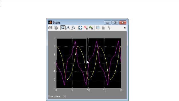
Scope and Floating Scope
To zoom in on data in just the x direction, click the middle Zoom toolbar button. Define the zoom region by positioning the pointer at one end of the region, pressing and holding down the mouse button, then moving the pointer to the other end of the region. This figure shows the Scope after you define the zoom region, but before you release the mouse button.
2-1464

Scope and Floating Scope
When you release the mouse button, the Scope displays the magnified region.
Zooming in the y direction works in the same way, except that you click the right most Zoom toolbar button before defining the zoom region.
Note Since Floating Scope does not buffer the data it displays, you cannot zoom the contents. Simulink disables (grays) the Zoom button on the toolbar of a Floating Scope.
Autoscaling the Scope Axes
User the Autoscale button to view the minimum and maximum points of your signals.
2-1465
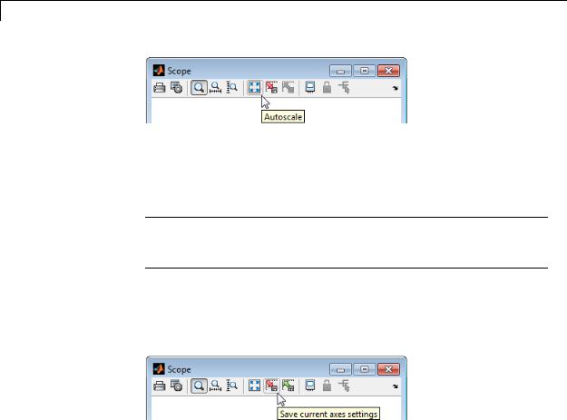
Scope and Floating Scope
If you click the Autoscale button while a simulation is running, the axes are autoscaled based on the data that appears on the current screen, and the autoscale limits are saved as the defaults. Then next simulation you run also uses the new axes limits.
Note Since the Floating Scope does not buffer the data it displays, you cannot autoscale the contents. Simulink disables the Autoscale button on the toolbar of a Floating Scope.
Saving and Restoring the Axes Settings
Use the Save current axes setting toolbar button to store the current x-axis and y-axis settings.
If you select the Save current axes settings button, the block specifies its current y-limits as the values of the Y-min and Y-max parameters (see “Y-Axis Limits” on page 2-1467. Similarly, the block specifies its current x-axis limits as the value of the Time range parameter (see “General Pane” on page 2-1458).
Use the Restore saved axes settings button to restore the saved axis settings.
2-1466

Scope and Floating Scope
Floating Scope
You can change a Scope block to a Floating Scope block from the toobar.
To add signals to a Floating Scope, click the Signal Selector button
 , and then select signals from your model. For more information, see “Signal Selector”.
Tip Before using a Floating Scope in a simulation, clear the Signal storage reuse check box in the Optimization > Signals and Parameters pane of the Configuration Parameters dialog box. For more information, see “Optimization Pane: Signals and Parameters”.
Y-Axis Limits
Set y-axis limits by right-clicking an axis (graph) and selecting Axes Properties. The following dialog box opens.
2-1467

Scope and Floating Scope
Y-min
Enter the minimum value for the y-axis.
Y-max
Enter the maximum value for the y-axis.
Title
Enter the title of the plot. You can include a signal label in the title by typing %<SignalLabel> as part of the title string (%<SignalLabel> is replaced by the signal label).
Note You cannot add a title to a Floating Scope window.
Time Offset
This figure shows the Scope block displaying the output of the vdp model. The simulation runs for 40 seconds. This scope shows the final 20 seconds of the simulation. The Time offset field displays the time corresponding to 0 on the horizontal axis. Therefore, you have to add the offset to the fixed time range values on the x-axis to get the actual time.
2-1468

Scope and Floating Scope
Creating a MATLAB Figure from Scope Block Data
If you need more drawing tools than provided with the Scope window, you can save scope data to the MATLAB workspace, replot the scope data in a Figure window, and then use the Plotting Tools.
1On the Scope window toolbar, click the Parameters button, and then select the History tab.
2Select the Save data to workspace check box, and in the Variable name field, enter a valid MATLAB variable name. For example, enter
ScopeData
3From the Format list, select Structure with time. Click OK or
Apply.
4Run a simulation.
2-1469

Scope and Floating Scope
5In the MATLAB Command Window, type: simplot(ScopeData)
A Figure window opens with a plot of the scope data.
6Edit the plot. See “Plots and Plotting Tools” in the MATLAB documentation.
Characteristics |
Sample Time |
Inherited from driving block or you can |
|
|
set |
|
States |
0 |
|
Multidimensionalized |
Yes |
|
|
|
2-1470

Second-Order Integrator, Second-Order Integrator
Limited
Purpose |
Integrate input signal twice |
Library Continuous
Description The Second-Order Integrator block and the Second-Order Integrator Limited block solve the second-order initial value problem:
d2 x = u, dt2
dx = dxo, dt t=0
x t=0 = xo,
where u is the input to the system. system with two continuous states:
The block is therefore a dynamic x and dx/dt.
Note These two states have a mathematical relationship, namely, that dx/dt is the derivative of x. In order to satisfy this relationship throughout the simulation, Simulink places various constraints on the block parameters and behavior.
The Second-Order Itegrator Limited block is identical to the Second-Order Integrator block with the exception that it defaults to limiting the states based on the specified upper and lower limits. For more information, see “Limiting the States” on page 2-1473.
Simulink software can use a number of different numerical integration methods to compute the outputs of the block. Each has advantages for specific applications. Use the Solver pane of the Configuration Parameters dialog box to select the technique best suited to your
application. (For more information, see “Choose a Solver”.) The selected solver computes the states of the Second-Order Integrator block at the current time step using the current input value.
2-1471

Second-Order Integrator, Second-Order Integrator
Limited
Use the block parameter dialog box to:
•Specify whether the source of each state initial condition is internal or external
•Specify a value for the state initial conditions
•Define upper and lower limits on either or both states
•Specify absolute tolerances for each state
•Specify names for both states
•Choose an external reset condition
•Enable zero-crossing detection
•Reinitialize dx/dt when x reaches saturation
•Specify that Simulink disregard the state limits and external reset for linearization operations
Defining Initial Conditions
You can define the initial conditions of each state individually as a parameter on the block dialog box or input one or both of them from an external signal.
•To define the initial conditions of state x as a block parameter, use the Initial condition source x drop-down menu to select internal and enter the value in the Initial condition x field.
•To provide the initial conditions from an external source for state x, specify the Initial condition source x parameter as external. An additional input port appears on the block.
•To define the initial conditions of state dx/dt as a block parameter, use the Initial condition source dx/dt drop-down menu to select internal and enter the value in the Initial condition dx/dt field.
•To provide the initial conditions from an external source for state dx/dt, specify Initial condition source dx/dt as external. An additional input port appears on the block.
2-1472
Second-Order Integrator, Second-Order Integrator
Limited
If you choose to use an external source for both state initial conditions, your block appears as follows.
Note
•Simulink does not allow initial condition values of inf or NaN.
•If you limit state x or state dx/dt by specifying saturation limits (see “Limiting the States” on page 2-1473) and one or more initial conditions are outside the corresponding limits, then the respective states are initialized to the closest valid value and a set of consistent initial conditions is calculated.
Limiting the States
When modeling a second-order system, you may need to limit the block states. For example, the motion of a piston within a cylinder is governed by Newton’s Second Law and has constraints on the piston position (x). With the Second-Order Integrator block, you can limit the states x and dx/dt independent of each other. You can even change the limits during simulation; however, you cannot change whether or not the states are limited. An important rule to follow is that an upper limit must be strictly greater than its corresponding lower limit.
2-1473

Second-Order Integrator, Second-Order Integrator
Limited
The block appearance changes when you limit one or both states.
Shown below is the appearance of the block with both states limited.
For each state, you can use the block parameter dialog box to set appropriate saturation limits.
Limiting x only
If you use the Second-Order Integrator Limited block, both states are limited by default. But you can also manually limit state x on the Second-Order Integrator block by selecting Limit x and entering the limits in the appropriate parameter fields.
2-1474

Second-Order Integrator, Second-Order Integrator
Limited
The block then determines the values of the states as follows:
•When x is less than or equal to its lower limit, the value of x is held at its lower limit and dx/dt is set to zero.
2-1475

Second-Order Integrator, Second-Order Integrator
Limited
•When x is in between its lower and upper limits, both states follow the trajectory given by the second-order ODE.
•When x is greater than or equal to its upper limit, the value of x is held at its upper limit and dx/dt is set to zero.
You can choose to reinitialize dx/dt to a new value at the time when x reaches saturation. See “Reinitializing dx/dt when x reaches saturation” on page 2-1480
Limiting dx/dt only
As with state x, state dx/dt is set as limited by default on the dx/dt pane of the Second-Order Integrator Limited parameter dialog box. You can manually set this parameter, Limit dx/dt, on the Second-Order Integrator block. In either case, you must enter the appropriate limits for dx/dt.
2-1476

Second-Order Integrator, Second-Order Integrator
Limited
If you limit only the state dx/dt, then the block determines the values of dx/dt as follows:
•When dx/dt is less than or equal to its lower limit, the value of dx/dt is held at its lower limit.
2-1477

Second-Order Integrator, Second-Order Integrator
Limited
•When dx/dt is in between its lower and upper limits, both states follow the trajectory given by the second-order ODE.
•When dx/dt is greater than or equal to its upper limit, the value of dx/dt is held at its upper limit.
When state dx/dt is held at it upper or lower limit, the value of x is governed by the first-order initial value problem:
dx = L, dt
x(tL) = xL,
where L is the dx/dt limit (upper or lower), tL is the time when dx/dt reaches this limit, and xL is the value of state x at that time.
Limiting Both States
When you limit both states, Simulink maintains mathematical consistency of the states by limiting the allowable values of the upper and lower limits for dx/dt. Such limitations are necessary to satisfy the following constraints:
•When x is at its saturation limits, the value of dx/dt must be zero.
•In order for x to leave the upper limit, the value of dx/dt must be strictly negative.
•In order for x to leave its lower limit, the value of dx/dt must be strictly positive.
Consequently, for such cases, the upper limit of dx/dt must be strictly positive and the lower limit of dx/dt must be strictly negative.
When both states are limited, the block determines the states as follows:
•Whenever x reaches its limits, the resulting behavior is the same as that described in “Limiting x only”.
2-1478

Second-Order Integrator, Second-Order Integrator
Limited
•Whenever dx/dt reaches one of its limits, the resulting behavior is the same as that described in “Limiting dx/dt only” — including the computation of x using a first-order ODE when dx/dt is held at one of its limits. In such cases, when x reaches one of its limits, it is held at that limit and dx/dt is set to zero.
•Whenever both reach their respective limits simultaneously, the state x behavior overrides dx/dt behavior to maintain consistency of the states.
When you limit both states, you can choose to reinitialize dx/dt at the time when state x reaches saturation. If the reinitialized value is outside specified limits on dx/dt, then dx/dt is reinitialized to the
closest valid value and a consistent set of initial conditions is calculated. See “Reinitializing dx/dt when x reaches saturation” on page 2-1480
Resetting the State
The block can reset its states to the specified initial conditions based on an external signal. To cause the block to reset its states, select one of the External reset choices on the Attributes pane. A trigger port appears on the block below its input port and indicates the trigger type.
•Select rising to reset the states when the reset signal rises from zero to a positive value, from a negative to a positive value, or a negative value to zero.
2-1479

Second-Order Integrator, Second-Order Integrator
Limited
•Select falling to reset the states when the reset signal falls from a positive value to zero, from a positive to a negative value, or from zero to negative.
•Select either to reset the states when the reset signal changes from zero to a nonzero value or changes sign.
The reset port has direct feedthrough. If the block output feeds back into this port, either directly or through a series of blocks with direct feedthrough, an algebraic loop results (see “Algebraic Loops”).
Enabling Zero-Crossing Detection
This parameter controls whether zero-crossing detection is enabled for this block. By default, the Enable zero-crossing detection parameter is selected on the Attributes pane. However, this parameter is only in affect if the Zero-crossing control, on the Solver pane of the Configuration Parameters dialog, is set to Use local settings. For more information, see “Zero-Crossing Detection”.
Reinitializing dx/dt when x reaches saturation
For certain modeling applications, dx/dt must be reinitialized when state x reaches its limits in order to pull x out of saturation immediately. You can achieve this by selecting Reinitialize dx/dt when x reaches saturation on the Attributes pane.
If this option is on, then at the instant when x reaches saturation, Simulink checks whether the current value of the dx/dt initial condition (parameter or signal) allows the state x to leave saturation immediately. If so, Simulink reinitializes state dx/dt with the value of the initial condition (parameter or signal) at that instant. If not, Simulink ignores this parameter at the current instant and sets dx/dt to zero to make the block states consistent.
This parameter only applies at the time when x actually reaches saturation limit. It does not apply at any future time when x is being held at saturation.
Refer to the sections on limiting the an example, see the sldemo_bounce
states for more information. For example.
2-1480

Second-Order Integrator, Second-Order Integrator
Limited
Disregarding State Limits and External Reset for Linearization
For cases where you simplify your model by linearizing it, you can have Simulink disregard the limits of the states and the external reset by selecting Ignore state limits and the reset for linearization.
Specifying the Absolute Tolerance for the Block Outputs
By default Simulink software uses the absolute tolerance value specified in the Configuration Parameters dialog box (see “Specifying Error Tolerances for Variable-Step Solvers”) to compute the output of the integrator blocks. If this value does not provide sufficient error control, specify a more appropriate value for state x in the Absolute tolerance x field and for state dx/dt in the Absolute tolerance dx/dt field of the parameter dialog box. Simulink uses the values that you specify to compute the state values of the block.
Specifying the Display of the Output Ports
You can control whether or not to display the x or the dx/dt output port using the ShowOutput parameter. You can display one output port or both; however, you must select at least one.
Specifying the State Names
You can specify the name of x states and dx/dt states using the StateNameX and StateNameDXDT parameters. However, you must specify names for either both or neither; you cannot specify names for just x or just dx/dt. Both state names must have identical type and length. Furthermore, the number of names must evenly divide the number of states.
Selecting All Options
When you select all options, the block icon looks like this.
2-1481

Second-Order Integrator, Second-Order Integrator
Limited
Data Type
Support
The Integrator block accepts and outputs signals of type double on its data ports. The external reset port accepts signals of type double
or Boolean.
For more information, see “Data Types Supported by Simulink” in the Simulink documentation.
2-1482
Second-Order Integrator, Second-Order Integrator
Limited
Parameters |
The x pane of the Second-Order Integrator block dialog box appears |
and |
as follows: |
Dialog |
|
Box |
|
The dx/dt pane of the Second-Order Integrator block dialog box appears as follows:
2-1483

Second-Order Integrator, Second-Order Integrator
Limited
The Attributes pane of the Second-Order Integrator block dialog box appears as follows:
2-1484

Second-Order Integrator, Second-Order Integrator
Limited
•“Initial condition source x” on page 2-1487
•“Initial condition x” on page 2-1488
•“Limit x” on page 2-1489
•“Upper limit x” on page 2-1490
•“Lower limit x” on page 2-1491
•“Absolute tolerance x” on page 2-1492
•“State name x” on page 2-1493
•“Initial condition source dx/dt” on page 2-1494
2-1485

Second-Order Integrator, Second-Order Integrator
Limited
•“Initial condition dx/dt” on page 2-1495
•“Limit dx/dt” on page 2-1496
•“Upper limit dx/dt” on page 2-1497
•“Lower limit dx/dt” on page 2-1498
•“Absolute tolerance dx/dt” on page 2-1499
•“State name dx/dt” on page 2-1500
•“External reset” on page 2-1501
•“Enable zero-crossing detection” on page 2-1710
•“Reinitialize dx/dt when x reaches saturation” on page 2-1503
•“Ignore state limits and the reset for linearization” on page 2-1504
•“Show output” on page 2-1505
2-1486

Second-Order Integrator, Second-Order Integrator
Limited
Initial condition source x
Specify the initial condition source for state x.
Settings
Default: internal
internal
Get the initial conditions of state x from the Initial condition x parameter.
external
Get the initial conditions of state x from an external block.
Tip
Simulink software does not allow the initial condition of this block to be inf or NaN.
Dependencies
Selecting internal enables the Initial condition x parameter.
Selecting external disables the Initial condition x parameter..
Command-Line Information
Parameter: ICSourceX
Type: string
Value: 'internal' | 'external'
Default: 'internal'
2-1487

Second-Order Integrator, Second-Order Integrator
Limited
Initial condition x
Specify the initial condition of state x.
Settings
Default: 0.0
Tip
Simulink software does not allow the initial condition of this block to be inf or NaN.
Dependencies
Setting Initial condition source x to internal enables this parameter.
Setting Initial condition source x to external disables this parameter.
Command-Line Information
Parameter: ICX
Type: vector or scalar
Value: any valid real value
Default: 0.0
2-1488

Second-Order Integrator, Second-Order Integrator
Limited
Limit x
Limit state x of the block to a value between the Lower limit x and
Upper limit x parameters.
Settings
Default: Off for Second-Order Integrator, On for Second-Order
Integrator Limited
 On
On
Limit state x to a value between the Lower limit x and Upper limit x parameters.
 Off
Off
Do not limit the state x output to a value between the Lower limit x and Upper limit x parameters.
Dependencies
This parameter enables Upper limit x parameter.
This parameter enables Lower limit x parameter.
Command-Line Information
Parameter: LimitX
Type: string
Value: 'on' | 'off'
Default: 'off' | 'on'
2-1489

Second-Order Integrator, Second-Order Integrator
Limited
Upper limit x
Specify the upper limit of state x.
Settings
Default: inf for Second-Order Integrator, 1 for Second-Order
Integrator Limited
Tip
The upper saturation limit for state x must be strictly greater than the lower saturation limit.
Dependency
Limit x enables this parameter.
Command-Line Information
Parameter: UpperLimitX
Type: scalar or vector
Value: any valid real value
Default: 'inf' | 1
2-1490

Second-Order Integrator, Second-Order Integrator
Limited
Lower limit x
Specify the lower limit of state x.
Settings
Default: inf for Second-Order Integrator, 0 for Second-Order
Integrator Limited
Tip
The lower saturation limit for state x must be strictly less than the upper saturation limit.
Dependencies
Limit x enables this parameter.
Command-Line Information
Parameter: LowerLimitX
Type: scalar or vector
Value: any valid value
Default: '-inf' | 0
2-1491

Second-Order Integrator, Second-Order Integrator
Limited
Absolute tolerance x
Specify the absolute tolerance for computing state x.
Settings
Default: auto
•You can enter auto, –1, a real scalar or a real vector.
•If you enter auto or –1, Simulink uses the absolute tolerance value in the Configuration Parameters dialog box (see “Solver Pane”) to compute state x.
•If you enter a real scalar value, that value overrides the absolute tolerance in the Configuration Parameters dialog box and is used for computing all x states.
•If you enter a real vector, the dimension of that vector must match the dimension of state x. These values override the absolute tolerance in the Configuration Parameters dialog box.
Command-Line Information
Parameter: AbsoluteToleranceX
Type: string, scalar, or vector with same dimension as x
Value: any positive real scalar or vector | {'auto'} |
{-1}
Default: 'auto'
2-1492
Second-Order Integrator, Second-Order Integrator
Limited
State name x
Assign a unique name to state x.
Settings
Default: ''
Tips
•To assign a name to a single state, enter the name between quotes, for example, position’.
•To assign names to multiple x states, enter a comma-delimited list surrounded by braces, for example, {’a’, ’b’, ’c’}. Each name must be unique.
•The state names apply only to the selected block.
•If you specify a state name for x, you must also specify a state name for dx/dt.
•State names for x and dx/dt must have identical types and lengths.
•The number of states must be evenly divided by the number of state names. You can specify fewer names than x states, but you cannot specify more names than x states. For example, you can specify two names in a system with four states. The first name applies
to the first two states and the second name to the last two states. However, you must be consistent and apply the same scheme to the state names for dx/dt.
•To assign state names with a variable in the MATLAB workspace, enter the variable without quotes. A variable can be a string or a cell array.
Command-Line Information
Parameter: StateNameX
Type: string
Value: any valid expression
Default: ''
2-1493

Second-Order Integrator, Second-Order Integrator
Limited
Initial condition source dx/dt
Specify the initial condition source for state dx/dt.
Settings
Default: internal
internal
Get the initial conditions of state dx/dt from the Initial condition dx/dt parameter.
external
Get the initial conditions of state dx/dt from an external block.
Tip
Simulink software does not allow the initial condition of this block to be inf or NaN.
Dependencies
Selecting internal enables the Initial condition dx/dt parameter.
Selecting external disables the Initial condition dx/dt parameter.
Command-Line Information
Parameter: ICSourceDXDT
Type: string
Value: 'internal' | 'external'
Default: 'internal'
2-1494

Second-Order Integrator, Second-Order Integrator
Limited
Initial condition dx/dt
Specify the initial condition of state dx/dt.
Settings
Default: 0.0
Tip
Simulink software does not allow the initial condition of this block to be inf or NaN.
Dependencies
Setting Initial condition source dx/dt to internal enables this parameter.
Setting Initial condition source dx/dt to external disables this parameter.
Command-Line Information
Parameter: ICDXDT
Type: scalar or vector
Value: any valid real value
Default: 0.0
2-1495

Second-Order Integrator, Second-Order Integrator
Limited
Limit dx/dt
Limit the dx/dt state of the block to a value between the Lower limit dx/dt and Upper limit dx/dt parameters.
Settings
Default: Off for Second-Order Integrator, On for Second-Order
Integrator Limited
 On
On
Limit state dx/dt of the block to a value between the Lower limit dx/dt and Upper limit dx/dt parameters.
 Off
Off
Do not limit state dx/dt of the block to a value between the
Lower limit dx/dt and Upper limit dx/dt parameters.
Tip
If you set saturation limits for x, then the interval defined by the Upper limit dx/dt and Lower limit dx/dt must contain zero.
Dependencies
This parameter enables Upper limit dx/dt.
This parameter enables Lower limit dx/dt.
Command-Line Information
Parameter: LimitDXDT
Type: string
Value: 'On' | 'Off'
Default: 'Off' | 'On'
2-1496

Second-Order Integrator, Second-Order Integrator
Limited
Upper limit dx/dt
Specify the upper limit for state dx/dt.
Settings
Default: 'inf'
Tip
If you limit x, then this parameter must have a strictly positive value.
Dependencies
Limit dx/dt enables this parameter.
Command-Line Information
Parameter: UpperLimitDXDT
Type: scalar or vector
Value: any valid real value
Default: 'inf'
2-1497

Second-Order Integrator, Second-Order Integrator
Limited
Lower limit dx/dt
Specify the lower limit for state dx/dt.
Settings
Default: '-inf'
Tip
If you limit x, then this parameter must have a strictly negative value.
Dependencies
Limit dx/dt enables this parameter.
Command-Line Information
Parameter: LowerLimitDXDT
Type: scalar or vector
Value: any valid real value
Default: '-inf'
2-1498

Second-Order Integrator, Second-Order Integrator
Limited
Absolute tolerance dx/dt
Specify the absolute tolerance for computing state dx/dt.
Settings
Default: auto
•You can enter auto or a numeric value.
•If you enter auto, then Simulink uses the absolute tolerance value in the Configuration Parameters dialog box (see “Solver Pane”) to compute the dx/dt output of the block.
•If you enter a numeric value, that value overrides the absolute tolerance in the Configuration Parameters dialog box.
Command-Line Information
Parameter: AbsoluteToleranceDXDT
Type: scalar
Value: any valid positive real value
Default: 'auto'
2-1499

Second-Order Integrator, Second-Order Integrator
Limited
State name dx/dt
Assign a unique name to state dx/dt.
Settings
Default: ''
Tips
•To assign a name to a single state, enter the name between quotes, for example, ’velocity’.
•To assign names to multiple dx/dt states, enter a comma-delimited list surrounded by braces, for example, {’a’, ’b’, ’c’}. Each name must be unique.
•The state names apply only to the selected block.
•If you specify a state name for dx/dt, you must also specify a state name for x.
•State names for x and dx/dt must have identical types and lengths.
•The number of states must be evenly divided by the number of state names. You can specify fewer names than dx/dt states, but you cannot specify more names than dx/dt states. For example, you can specify two names in a system with four states. The first name applies to the first two states and the second name to the last two states. However, you must be consistent and apply the same scheme to the state names for x.
•To assign state names with a variable in the MATLAB workspace, enter the variable without quotes. A variable can be a string or a cell array.
Command-Line Information
Parameter: StateNameDXDT
Type: string
Value: any valid expression
Default: ''
2-1500

Second-Order Integrator, Second-Order Integrator
Limited
External reset
Reset the states to their initial conditions when a trigger event occurs in the reset signal.
Settings
Default: none
none
Do not reset the state to initial conditions.
rising
Reset the state when the reset signal rises from a zero to a positive value or from a negative to a positive value.
falling
Reset the state when the reset signal falls from a positive value to zero or from a positive to a negative value.
either
Reset the state when the reset signal changes from zero to a nonzero value or changes sign.
Command-Line Information
Parameter: ExternalReset
Type: string
Value: 'none' | 'rising' | 'falling' | 'either'
Default: 'none'
2-1501

Second-Order Integrator, Second-Order Integrator
Limited
Enable zero-crossing detection
Select to enable zero-crossing detection. For more information, see “Zero-Crossing Detection” in the Simulink documentation.
Settings
Default: On
 On
On
Enable zero-crossing detection.
 Off
Off
Do not enable zero-crossing detection.
Command-Line Information
See “Block-Specific Parameters” on page 8-109 for the command-line information.
2-1502
Second-Order Integrator, Second-Order Integrator
Limited
Reinitialize dx/dt when x reaches saturation
At the instant when state x reaches saturation, reset dx/dt to its current initial conditions.
Settings
Default: Off
 On
On
Reset dx/dt to its initial conditions when x becomes saturated.
 Off
Off
Do not reset dx/dt to its initial conditions when x becomes saturated.
Tip
The dx/dt initial condition must have a value that enables x to leave saturation immediately. Otherwise, Simulink ignores the initial conditions for dx/dt to preserve mathematical consistency of block states.
Command-Line Information
Parameter: ReinitDXDTwhenXreachesSaturation
Type: string
Value: 'on' | 'off'
Default: 'off'
2-1503

Second-Order Integrator, Second-Order Integrator
Limited
Ignore state limits and the reset for linearization
For linearization purposes, have Simulink ignore the specified state limits and the external reset.
Settings
Default: Off
 On
On
Ignore the specified state limits and the external reset.
 Off
Off
Apply the specified state limits and the external reset setting.
Command-Line Information
Parameter: IgnoreStateLimitsAndResetForLinearization
Type: string
Value: 'on' | 'off'
Default: 'off'
2-1504

Second-Order Integrator, Second-Order Integrator
Limited
Show output
Specify the output ports on the block.
Settings
Default: both
both
Show both x and dx/dt output ports.
x
Show only the x output port.
dx/dt
Show only the dx/dt output port.
Command-Line Information
Parameter: ShowOutput
Type: string
Value: 'both' | 'x' | 'dxdt'
Default: 'both'
2-1505

Selector
Purpose |
Select input elements from vector, matrix, or multidimensional signal |
Library |
Signal Routing |
Description |
The Selector block generates as output selected or reordered elements |
|
of an input vector, matrix, or multidimensional signal. |
|
A Selector block accepts vector, matrix, or multidimensional signals as |
|
input. The parameter dialog box and the block’s appearance change to |
|
reflect the number of dimensions of the input. |
|
Based on the value you enter for the Number of input dimensions |
|
parameter, a table of indexing settings is displayed. Each row of the |
|
table corresponds to one of the input dimensions in Number of input |
|
dimensions. For each dimension, you define the elements of the |
|
signal to work with. Specify a vector signal as a 1-D signal and a |
|
matrix signal as a 2-D signal. When you configure the Selector block for |
|
multidimensional signal operations, the block icon changes. |
|
For example, assume a 6-D signal with a one-based index mode. The |
|
table of the Selector block dialog changes to include one row for each |
|
dimension. Suppose that you define each dimension with the following |
|
entries: |
|
1 Index Option, select Select all |
|
2 |
|
• Index Option, select Starting index (dialog) |
|
• Index, enter 2 |
|
• Output Size, enter 5 |
|
3 |
|
• Index Option, select Index vector (dialog) |
|
• Index, enter [1 3 5] |
2-1506

Selector
Data Type
Support
4
•Index Option, select Starting index (port)
•Output Size, enter 8
5 Index Option, select Index vector (port)
6 Index Option, select Starting and ending indices (port)
The output will be Y=U(1:end,2:6,[1 3 5],Idx4:Idx4+7,Idx5, Idx6(1):Idx6(2)), where Idx4, Idx5, and Idx6 are the index ports for dimensions 4, 5, and 6.
You can use an array of buses as an input signal to a Selector block. For details about defining and using an array of buses, see “Combine Buses into an Array of Buses”.
The data port of the Selector block accepts signals of any signal type and any data type that Simulink supports, including fixed-point and enumerated data types. The data port accepts mixed-type signals. The index port accepts built-in data types, but not Boolean. The elements of the output have the same type as the corresponding selected input elements.
For more information, see “Data Types Supported by Simulink” in the Simulink documentation.
2-1507

Selector
Parameters and Dialog Box
Number of input dimensions
Enter the number of dimensions of the input signal.
Index mode
Specifies the indexing mode: One-based or Zero-based. If One-based is selected, an index of 1 specifies the first element of the input vector, 2, the second element, and so on. If Zero-based is selected, an index of 0 specifies the first element of the input vector, 1, the second element, and so on.
2-1508

Selector
Index Option
Define, by dimension, how the elements of the signal are to be indexed. From the list, select:
•Select all
No further configuration is required. All elements are selected.
•Index vector (dialog)
Enables the Index column. Enter the vector of indices of the elements.
•Index vector (port)
No further configuration is required.
•Starting index (dialog)
Enables the Index and Output Size columns. Enter the starting index of the range of elements to select in the Index column and the number of elements to select in the Output Size column.
•Starting index (port)
Enables the Output Size column. Enter the number of elements to be selected in the Output Size column.
•Starting and ending indices (port)
No further configuration is required.
The Index and Output Size columns appear as needed.
Index
If the Index Option is Index vector (dialog), enter the index of each element in which you are interested.
If the Index Option is Starting index vector (dialog), enter the starting index of the range of elements to be selected.
2-1509

Selector
Output Size
Enter the width (number of elements from the starting point) of the block output signal.
Input port size
Specify the width of the block input signal (-1 for inherited) — 1-D signals only.
Sample time (-1 for inherited)
Specify the time interval between samples. To inherit the sample time, set this parameter to -1. See “Specify Sample Time” in the online documentation for more information.
Note For 1-D signals, the Sample time parameter is available only when Index Option is Starting index (port), Index
vector (port), or Starting and ending indices (port). For all other Index Option settings, the Selector block becomes a virtual block and the Sample time parameter does not appear.
Examples |
The sldemo_dblcart1 model shows how to use the Selector block. |
|
Characteristics |
|
|
Sample Time |
Specified in the Sample time parameter |
|
|
Dimensionalized |
Yes |
|
Multidimensionalized |
Yes |
|
Virtual |
Yes, when Number of input |
|
|
dimensions is 1 and Index Option is |
|
|
Select all, Index vector (dialog), or |
|
|
Starting index (dialog) |
|
|
For more information, see “Virtual |
|
|
Blocks” in the Simulink documentation. |
|
Zero-Crossing Detection |
No |
|
|
|
2-1510

S-Function
Purpose
Library
Description
Data Type
Support
Include S-function in model
User-Defined Functions
The S-Function block provides access to S-functions from a block diagram. The S-function named as the S-function name parameter can be a Level-1 MATLAB or a Level-1 or Level-2 C MEX S-function (see “S-Function Basics” for information on how to create S-functions).
Note Use the Level-2 MATLAB S-Function block to include a Level-2 MATLAB S-function in a block diagram.
The S-Function block allows additional parameters to be passed directly to the named S-function. The function parameters can be specified
as MATLAB expressions or as variables separated by commas. For example,
A, B, C, D, [eye(2,2);zeros(2,2)]
Note that although individual parameters can be enclosed in brackets, the list of parameters must not be enclosed in brackets.
The S-Function block displays the name of the specified S-function and the number of input and output ports specified by the S-function. Signals connected to the inputs must have the dimensions specified by the S-function for the inputs.
Depends on the implementation of the S-Function block.
2-1511

S-Function
Parameters and Dialog Box
S-function name
The S-function name.
S-function parameters
Additional S-function parameters. See the preceding block description for information on how to specify the parameters.
S-function modules
This parameter applies only if this block represents a C MEX S-function and you intend to use the Simulink Coder software to generate code from the model containing the
2-1512
S-Function
block. For information on using this parameter, see “Specify Additional Source Files for an S-Function” in the Simulink Coder documentation.
Characteristics |
Direct Feedthrough |
Depends on contents of S-function |
|
Sample Time |
Depends on contents of S-function |
|
Scalar Expansion |
Depends on contents of S-function |
|
Dimensionalized |
Depends on contents of S-function |
|
Multidimensionalized |
Yes |
|
Zero-Crossing Detection |
No |
|
|
|
2-1513

S-Function Builder
Purpose
Library
Description
Data Type
Support
Parameters and Dialog Box
Create S-function from C code that you provide
User-Defined Functions
The S-Function Builder block creates a C MEX S-function from specifications and C source code that you provide. See “Build S-Functions Automatically” for detailed instructions on using the S-Function Builder block to generate an S-function.
Instances of the S-Function Builder block also serve as wrappers for generated S-functions in Simulink models. When simulating a model containing instances of an S-Function Builder block, Simulink software invokes the generated S-function associated with each instance to compute the instance’s output at each time step.
Note The S-Function Builder block does not support masking. However, you can mask a Subsystem block that contains an S-Function Builder block. For more information, see “Masking”.
The S-Function Builder can accept and output complex, 1-D, or 2-D signals and nonvirtual buses. For each of these cases, the signals must have a data type that Simulink supports.
For more information, see “Data Types Supported by Simulink” in the Simulink documentation.
See “S-Function Builder Dialog Box” in the online documentation for information on using the S-Function Builder block’s parameter dialog box.
2-1514

Shift Arithmetic
Purpose |
Shift bits or binary point of signal |
|
|
|
Library |
Logic and Bit Operations |
|
|
|
Description |
Supported Shift Operations |
|
|
|
|
The Shift Arithmetic block can shift the bits or the binary point of an |
|
||
|
input signal, or both. |
|
|
|
|
For example, shifting the binary point on an input of data type sfix(8), |
|
||
|
by two places to the right and left, gives these decimal values. |
|
||
|
|
|
|
|
|
|
|
Decimal |
|
|
Shift Operation |
Binary Value |
Value |
|
|
No shift (original number) |
11001.011 |
–6.625 |
|
|
Binary point shift right by two places |
1100101.1 |
–26.5 |
|
|
Binary point shift left by two places |
110.01011 |
–1.65625 |
|
|
This block performs arithmetic bit shifts on signed numbers. Therefore, |
|
||
|
the block recycles the most significant bit for each bit shift. Shifting the |
|
||
|
bits on an input of data type sfix(8), by two places to the right and |
|
||
|
left, gives these decimal values. |
|
|
|
|
|
|
|
|
|
|
|
Decimal |
|
|
Shift Operation |
Binary Value |
Value |
|
|
No shift (original number) |
11001.011 |
–6.625 |
|
|
Bit shift right by two places |
11110.010 |
–1.75 |
|
|
Bit shift left by two places |
00101.100 |
5.5 |
|
|
|
|
|
|
2-1515

Shift Arithmetic
Data Type
Support
The block supports input signals of the following data types:
|
Input Signal |
|
Supported Data Types |
|
|
u |
|
• Floating point |
|
|
|
|
• Built-in integer |
|
|
|
|
• Fixed point |
|
|
s |
|
• Floating point |
|
|
|
|
• Built-in integer |
|
|
|
|
• Fixed-point integer |
|
|
The following rules determine the |
output data type: |
|
|
|
|
|
|
|
|
Data Type of |
Output Data Type |
|
|
|
Input u |
|
|
|
|
Floating point |
Same as input u |
|
|
|
Built-in |
• Sign of u |
|
|
|
integer or |
• Word length of u |
|
|
|
fixed point |
|
||
|
• Slope of u * 2^(max(binary points to shift)) |
|
||
|
|
|
||
|
|
• Bias of u * 2^(max(binary points to shift |
|
|
|
|
– bits to shift)), for bit shifts where the |
|
|
|
|
direction is bidirectional or right |
|
|
|
|
• Bias of u * 2^(max(binary points to shift |
|
|
|
|
+ bits to shift)), for bit shifts where the |
|
|
|
|
direction is left |
|
|
2-1516

Shift Arithmetic
The block parameters support the following data types:
|
Parameter |
Supported Data Types |
|
|
Bits to shift: Number |
• Built-in integer |
|
|
|
• Fixed-point integer |
|
|
Binary points to shift |
• Built-in integer |
|
|
|
• Fixed-point integer |
|
|
|
|
|
For more information, see “Data Types Supported by Simulink” in the Simulink documentation.
2-1517

Shift Arithmetic
Parameters The Shift Arithmetic block dialog box appears as follows:
and Dialog Box
2-1518

Shift Arithmetic
Bits to shift: Source
Specify whether to enter the bits to shift on the dialog box or to inherit the values from an input port.
Bits to shift: Direction
Specify the direction in which to shift bits: left, right, or bidirectional.
Bits to shift: Number
Specify a scalar, vector, or array of bit shift values. This parameter is available when Bits to shift: Source is Dialog.
|
If the direction is... |
Then... |
|
|
Left or Right |
Use positive integers to specify |
|
|
|
bit shifts. |
|
|
Bidirectional |
Use positive integers for right |
|
|
|
shifts and negative integers |
|
|
|
for left shifts. |
|
Binary points to shift
Specify an integer number of places to shift the binary point of the input signal. A positive value indicates a right shift, while a negative value indicates a left shift.
Diagnostic for out-of-range shift value
Specify whether to produce a warning or error during simulation when the block contains an out-of-range shift value. Options include:
•None — No warning or error appears.
•Warning — Display a warning in the MATLAB Command Window and continue the simulation.
•Error — Halt the simulation and display an error in the Simulation Diagnostics Viewer.
For more information, see “Simulation and Accelerator Mode Results for Out-of-Range Bit Shift Values” on page 2-1522.
2-1519

Shift Arithmetic
Check for out-of-range ’Bits to shift’ in generated code
Select this check box to include conditional statements in the generated code that protect against out-of-range bit shift values. This check box is available when Bits to shift: Source is Input
port.
For more information, see “Code Generation for Out-of-Range Bit Shift Values” on page 2-1524.
2-1520

Shift Arithmetic
Out-of-Range
Bit Shifts
Definition of an Out-of-Range Bit Shift
Suppose that WL is the input word length. The shaded regions in the following diagram show out-of-range bit shift values for left and right shifts.
Similarly, the shaded regions in the following diagram show out-of-range bit shift values for bidirectional shifts.
2-1521

Shift Arithmetic
The diagnostic for out-of-range bit shifts responds as follows, depending on the mode of operation:
|
Mode |
Diagnostic for out-of-range shift value |
|
|
|
|
|
None |
Warning |
Error |
|
|
Simulation |
Do not report any |
Report a warning but |
Report an error and |
|
|
|
warning or error. |
continue simulation. |
stop simulation. |
|
|
Accelerator modes |
Has no effect. |
|
|
|
|
and code generation |
|
|
|
|
Simulation and Accelerator Mode Results for Out-of-Range Bit Shift Values
Suppose that U is the input, WL is the input word length, and Y is the output. The output for an out-of-range bit shift value for left shifts is as follows:
2-1522
Shift Arithmetic
Similarly, the output for an out-of-range bit shift value for right shifts is as follows:
For bidirectional shifts, the output for an out-of-range bit shift value is as follows:
2-1523

Shift Arithmetic
Code Generation for Out-of-Range Bit Shift Values
For the generated code, the method for handling out-of-range bit shifts depends on the setting of Check for out-of-range ’Bits to shift’ in generated code.
|
Check Box |
Generated Code |
Simulation Results |
|
|
Setting |
|
Compared to |
|
|
|
|
Generated Code |
|
|
Selected |
Includes conditional |
Simulation and |
|
|
|
statements to protect |
Accelerator mode results |
|
|
|
against out-of-range bit |
match those of code |
|
|
|
shift values. |
generation. |
|
|
Cleared |
Does not protect against |
• For in-range values, |
|
|
|
out-of-range bit shift |
simulation and |
|
|
|
values. |
Accelerator mode |
|
|
|
|
results match those |
|
|
|
|
of code generation. |
|
|
|
|
• For out-of-range |
|
|
|
|
values, the code |
|
|
|
|
generation results |
|
|
|
|
are compiler specific. |
|
For right shifts on signed negative inputs, most C compilers use an arithmetic shift instead of a logical shift. Generated code for the Shift Arithmetic block depends on this compiler behavior.
2-1524

Shift Arithmetic
Examples Block Output for Right Bit Shifts
The following model compares the behavior of right bit shifts using the dialog box versus the block input port.
The key block parameter settings of the Constant blocks are:
|
Block |
Parameter |
Setting |
|
|
Constant and |
Constant value |
124 |
|
|
Constant1 |
Output data type |
int8 |
|
|
|
|
||
|
Dynamic bit shift |
Constant value |
2 |
|
|
|
Output data type |
Inherit: Inherit |
|
|
|
|
from 'Constant |
|
|
|
|
value' |
|
|
|
|
|
|
2-1525

Shift Arithmetic
The key block parameter settings of the Shift Arithmetic blocks are:
|
Block |
Parameter |
Setting |
|
|
Bit shift from |
Bits to shift: |
Dialog |
|
|
dialog |
Source |
|
|
|
|
Bits to shift: |
Right |
|
|
|
Direction |
|
|
|
|
Bits to shift: |
2 |
|
|
|
Number |
|
|
|
Bit shift from |
Bits to shift: |
Input port |
|
|
input |
Source |
|
|
|
|
Bits to shift: |
Right |
|
|
|
Direction |
|
|
The top Shift Arithmetic block takes an input of 124, which corresponds to 01111100 in binary format. Shifting the number of bits two places to the right produces 00011111 in binary format. Therefore, the block outputs 31.
The bottom Shift Arithmetic block performs the same operation as the top block. However, the bottom block receives the bit shift value
through an input port instead of the dialog box. By supplying this value as an input signal, you can change the number of bits to shift during simulation.
2-1526

Shift Arithmetic
Block Output for Binary Point Shifts
The following model shows the effect of binary point shifts.
The key block parameter settings of the Constant blocks are:
|
Block |
Parameter |
Setting |
|
|
Constant and |
Constant value |
124 |
|
|
Constant1 |
Output data type |
int8 |
|
|
|
|
||
|
|
|
|
|
2-1527

Shift Arithmetic
The key block parameter settings of the Shift Arithmetic blocks are:
|
Block |
Parameter |
Setting |
|
|
Shift binary point |
Bits to shift: |
Dialog |
|
|
3 places to the |
Source |
|
|
|
right |
Bits to shift: |
Bidirectional |
|
|
|
|
||
|
|
Direction |
|
|
|
|
Bits to shift: |
0 |
|
|
|
Number |
|
|
|
|
Binary points to |
3 |
|
|
|
shift: Number |
|
|
|
Shift binary point |
Bits to shift: |
Dialog |
|
|
3 places to the |
Source |
|
|
|
left |
Bits to shift: |
Bidirectional |
|
|
|
|
||
|
|
Direction |
|
|
|
|
Bits to shift: |
0 |
|
|
|
Number |
|
|
|
|
Binary points to |
–3 |
|
|
|
shift: Number |
|
|
The top Shift Arithmetic block takes an input of 124, which corresponds to 01111100 in binary format. Shifting the binary point three places to the right produces 01111100000 in binary format. Therefore, the top block outputs 995.
The bottom Shift Arithmetic block also takes an input of 124. Shifting the binary point three places to the left produces 01111.100 in binary format. Therefore, the bottom block outputs 15.5.
Characteristics |
Direct Feedthrough |
Yes |
|
Sample Time |
Inherited from the driving block |
|
|
|
2-1528

Shift Arithmetic
Scalar Expansion |
Yes |
Dimensionalized |
Yes |
Multidimensionalized |
Yes, for the input port that |
|
specifies bit shift values |
Zero-Crossing Detection |
No |
|
|
2-1529

Sign
Purpose |
Indicate sign of input |
|
|
|
Library |
Math Operations |
|
|
|
Description |
Block Behavior for Real Inputs |
|
|
|
|
For real inputs, the Sign block outputs the sign of the input: |
|
||
|
|
|
|
|
|
Input |
|
Output |
|
|
Greater than zero |
|
1 |
|
|
Equal to zero |
|
0 |
|
|
Less than zero |
|
–1 |
|
|
|
|
|
|
For vector and matrix inputs, the block outputs a vector or matrix where each element is the sign of the corresponding input element, as shown in this example:
Block Behavior for Complex Inputs
When the input u is a complex scalar, the block output matches the
MATLAB result for:
sign(u) = u./ abs(u)
When an element of a vector or matrix input is complex, the block uses the same formula that applies to scalar input, as shown in this example:
2-1530

Sign
Data Type
Support
The Sign block supports real inputs of the following data types:
•Floating point
•Built-in integer
•Fixed point
•Boolean
The block supports complex inputs only for floating-point data types, double and single. The output uses the same data type as the input.
For more information, see “Data Types Supported by Simulink” in the Simulink documentation.
2-1531

Sign
Parameters and Dialog Box
Examples
Enable zero-crossing detection
Select to enable zero-crossing detection. For more information, see “Zero-Crossing Detection” in the Simulink documentation.
Sample time (-1 for inherited)
Specify the time interval between samples. To inherit the sample time, set this parameter to -1. See “Specify Sample Time” in the Simulink documentation for more information.
The following Simulink examples show how to use the Sign block:
•sldemo_fuelsys (in the Engine Gas Dynamics/Throttle & Manifold/Throttle subsystem)
•sldemo_hardstop
2-1532
Sign
Characteristics |
Direct Feedthrough |
Yes |
|
Sample Time |
Specified in the Sample time |
|
|
parameter |
|
Scalar Expansion |
N/A |
|
Dimensionalized |
Yes |
|
Multidimensionalized |
No |
|
Zero-Crossing Detection |
Yes, if enabled |
|
|
|
2-1533

Signal Builder
Purpose |
Create and generate interchangeable groups of signals whose |
|
waveforms are piecewise linear |
Library |
Sources |
Description |
|
|
The Signal Builder block allows you to create interchangeable groups of |
|
piecewise linear signal sources and use them in a model. See “Signal |
|
Groups” in the Simulink documentation. |
|
|
|
Note Use the signalbuilder function to create and access Signal |
|
Builder blocks programmatically. |
Data Type |
The Signal Builder block outputs a virtual nonhierarchical bus, scalar, |
Support |
or array of real signals of type double. |
|
For more information, see “Data Types Supported by Simulink” in the |
|
Simulink documentation. |
Parameters |
The Signal Builder block has the same dialog box as that of a Subsystem |
and |
block. To display the dialog box, right-click the block and select |
Dialog |
Subsystem Parameters. |
Box |
|
Examples |
The following examples show how to use the Signal Builder block: |
|
• sldemo_pid2dof |
2-1534

Signal Builder
• sf_test_vectors
Characteristics |
Sample Time |
Specified in the Sample time |
|
|
parameter, accessible by selecting |
|
|
File > Simulation Options in the |
|
|
Signal Builder block |
|
|
• Zero represents a continuous sample |
|
|
time. |
|
|
• A positive integer represents a |
|
|
discrete sample time. |
|
Scalar Expansion |
Yes, of parameters |
|
Dimensionalized |
Yes |
|
Zero Crossing |
Yes |
|
|
|
2-1535

Signal Conversion
Purpose |
Convert signal to new type without altering signal values |
Library |
Signal Attributes |
Description |
The Signal Conversion block converts a signal from one type to another. |
|
Use the Output parameter to select the type of conversion to perform. |
Data Type The Signal Conversion block accepts signals of the following data types:
Support
•Scalar
•Floating point
•Built-in integer
•Fixed point
•Boolean
•Enumerated
•Virtual and nonvirtual bus signals
You can use an array of buses as an input signal to a Signal Conversion block. For details about defining and using an array of buses, see “Combine Buses into an Array of Buses”.
For more information about data types, see “Data Types Supported by Simulink” in the Simulink documentation.
2-1536
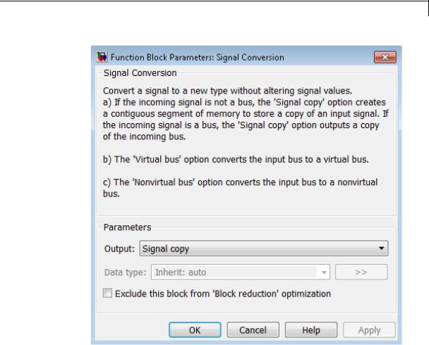
Signal Conversion
Parameters and Dialog Box
Output
Specify the type of conversion to perform. The type of conversion that you use depends on your modeling goal.
2-1537

Signal Conversion
|
Modeling Goal |
Output Option |
|
Reduce generated code for a muxed signal. |
Signal copy |
|
For an example involving Simulink |
|
|
Coder software, see “Reusable Code and |
|
|
Referenced Models”. |
|
|
Connect a block with a constant sample |
Signal copy |
|
time to an output port of an enabled |
|
|
subsystem. |
|
|
For more information, see “Using Blocks |
|
|
with Constant Sample Times in Enabled |
|
|
Subsystems”. |
|
|
Pass a bus signal, or array of buses |
Signal copy |
|
signal, whose components have different |
|
|
data types to a nonvirtual Inport block |
|
|
in an atomic subsystem that has direct |
|
|
feedthrough. |
|
|
“Composite Signals” in the Simulink |
|
|
documentation for more information. |
|
|
Save memory by converting a nonvirtual |
Virtual bus |
|
bus to a virtual bus. |
|
|
Pass a virtual bus signal to a modeling |
Nonvirtual bus |
|
construct that requires a nonvirtual bus, |
|
|
such as a Model block. |
|
|
Pass a nonvirtual bus signal from a Bus |
Nonvirtual bus |
|
Selector block. |
|
•The Signal copy option is the default. The type of conversion that the Signal Conversion block performs using the Signal copy option depends on the type of input signal.
2-1538

Signal Conversion
|
Type of Input Signal |
Conversion that the Signal |
|
|
|
Copy Option Performs |
|
|
Muxed (nonbus) signal |
Converts the muxed signal, |
|
|
|
whose elements occupy |
|
|
|
discontiguous areas of |
|
|
|
memory, to a vector signal, |
|
|
|
whose elements occupy |
|
|
|
contiguous areas of memory. |
|
|
|
The conversion allocates a |
|
|
|
contiguous area of memory |
|
|
|
for the elements of the muxed |
|
|
|
signal and copies the values |
|
|
|
from the discontiguous areas |
|
|
|
(represented by the block’s |
|
|
|
input) to the contiguous areas |
|
|
|
(represented by the block’s |
|
|
|
output) at each time step. |
|
|
Bus signal |
Outputs a contiguous copy |
|
|
|
of the bus signal that is |
|
|
|
the input to the Signal |
|
|
|
Conversion block. |
|
For an array of buses input signal, use the Signal copy option.
In the following example, a muxed signal inputs to a Signal Conversion block that has the Output parameter set to Signal copy. The Signal Conversion block converts the input signal to a vector.
2-1539
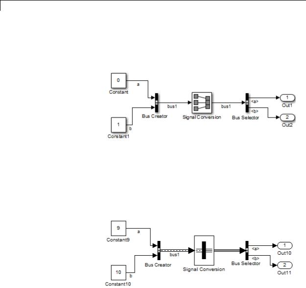
Signal Conversion
In the following example, a nonvirtual bus signal from a Bus Creator block inputs to a Signal Conversion block that has Output set to Signal copy. The Signal Conversion block creates another contiguous copy of the input bus signal.
•The Virtual bus option converts a nonvirtual bus to a virtual bus.
In the following example, a Bus Creator block inputs to a Signal Conversion block that has Output set to Virtual bus. The Signal Conversion block converts the nonvirtual bus signal from the Bus Creator block to a virtual bus signal that inputs to the Bus Selector block.
•The Nonvirtual bus option converts a virtual bus to a nonvirtual bus.
2-1540

Signal Conversion
In the following example, the Signal Conversion block converts a virtual bus signal from the first Bus Selector block to a nonvirtual bus signal that inputs to the second Bus Selector block. The Signal Conversion block has its Output parameter set to Nonvirtual bus, and specifies a bus object that matches the bus signal hierarchy of the bus that the first Bus Creator block outputs.
Data type
Specify the output data type of the nonvirtual bus that the Signal Conversion block produces.
This option is available only when you set the Output parameter to Nonvirtual bus.
The default option is Inherit: auto, which uses a rule that inherits a data type.
You must specify a Simulink.Bus object in the Data type parameter for one or both of the following blocks:
•Signal Conversion block
•An upstream Bus Creator block
If you specify a bus object for the Signal Conversion block, but not for its upstream Bus Creator block, then use a bus object that
2-1541

Signal Conversion
matches the hierarchy of the bus that upstream Bus Creator block outputs.
If you specify a bus object for both the Signal Conversion block and its upstream Bus Creator block, use the same bus object for both blocks.
You can select the button to the right of the Data type parameter to open the Data Type Assistant, which helps you to set the Data type parameter.
See “Specify Block Output Data Types” in Simulink User’s Guide for more information.
Exclude this block from ’Block reduction’ optimization
This option is available only when you set the Output parameter to Signal copy. If the elements of the input signal occupy contiguous areas of memory, then as an optimization, Simulink software eliminates the block from the compiled model . If
you select the Exclude this block from ’Block reduction’ optimization check box, the optimization occurs the next time you compile the model. For more information, see “Block reduction”.
Characteristics |
Sample Time |
Inherited from the driving block |
|
Scalar Expansion |
n/a |
|
Dimensionalized |
n/a |
|
Multidimensionalized |
Yes |
|
Zero-Crossing Detection |
No |
|
|
|
2-1542
Signal Generator
Purpose |
Generate various waveforms |
Library Sources
2-1543
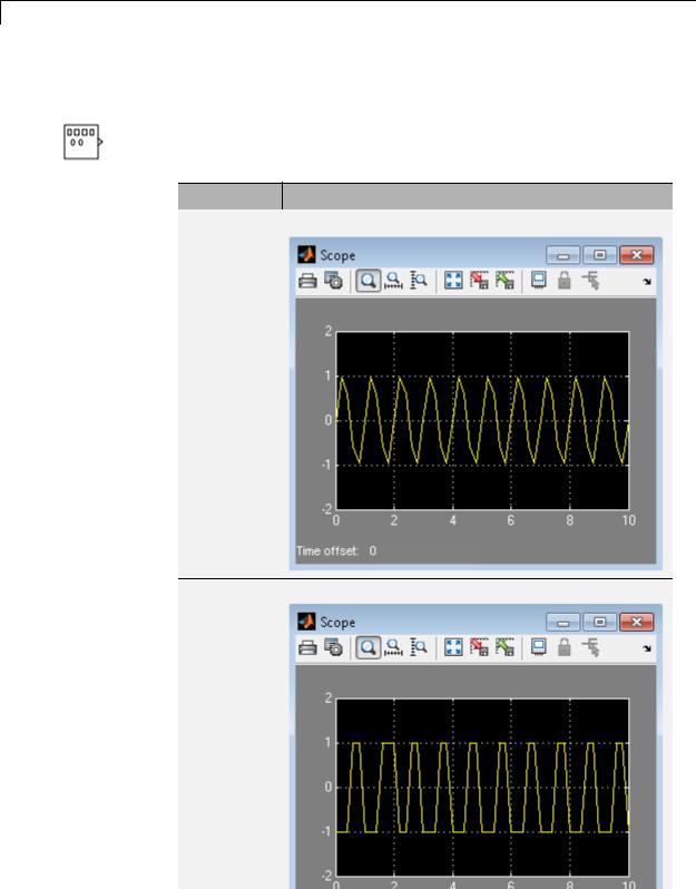
Signal Generator
Description Supported Operations
The Signal Generator block can produce one of four different waveforms: sine wave, square wave, sawtooth wave, and random wave. You can express signal parameters in Hertz (the default) or radians per second. Using default parameter values, you get one of the following waveforms:
Waveform Scope Output
Sine wave
Square wave
2-1544

Signal Generator
Waveform Scope Output
Sawtooth wave
Random wave
2-1545

Signal Generator
A negative Amplitude parameter value causes a 180-degree phase shift. You can generate a phase-shifted wave at other than 180 degrees in many ways. For example, you can connect a Clock block signal to a MATLAB Function block and write the equation for the specific wave.
You can vary the output settings of the Signal Generator block while a simulation is in progress. This is useful to determine quickly the response of a system to different types of inputs.
The Amplitude and Frequency parameters determine the amplitude and frequency of the output signal. The parameters must be of the same dimensions after scalar expansion. If you clear the Interpret vector parameters as 1-D check box, the block outputs a signal of the same dimensions as the Amplitude and Frequency parameters (after scalar expansion). If you select the Interpret vector parameters as 1-D check box, the block outputs a vector (1-D) signal if the Amplitude and Frequency parameters are row or column vectors, that is, single row or column 2-D arrays. Otherwise, the block outputs a signal of the same dimensions as the parameters.
2-1546

Signal Generator
Solver Considerations
If your model uses a fixed-step solver, Simulink uses the same step size for the entire simulation. In this case, the Signal Generator block output provides a uniformly sampled representation of the ideal waveform.
If your model uses a variable-step solver, Simulink might use different step sizes during the simulation. In this case, the Signal Generator block output does not always provide a uniformly sampled representation of the ideal waveform. To ensure that the block output is a uniformly sampled representation, add a Hit Crossing block directly downstream of the Signal Generator block. The following models show the difference in Signal Generator block output with and without the Hit Crossing block.
2-1547

Signal Generator
Model That Uses a Variable-Step |
Signal Generator Block Output |
Solver |
|
|
|
|
|
2-1548

Signal Generator
Data Type
Support
Parameters and Dialog Box
The Signal Generator block outputs a scalar or array of real signals of type double.
For more information, see “Data Types Supported by Simulink” in the Simulink documentation.
Wave form
Specify the wave form: a sine wave, square wave, sawtooth wave, or random wave. The default is a sine wave. This parameter cannot change while a simulation is running.
2-1549

Signal Generator
Time
Specify whether to use simulation time as the source of values for the waveform’s time variable or an external signal. If you specify an external time source, the block displays an input port for the time source.
Amplitude
Specify the signal amplitude. The default is 1.
Frequency
Specify the signal frequency. The default is 1.
Units
Specify the signal units: Hertz or radians/sec. The default is Hertz.
Interpret vector parameters as 1-D
If selected, column or row matrix values for the Amplitude and Frequency parameters result in a vector output signal (see “Determining the Output Dimensions of Source Blocks”). This option is not available when an external signal specifies time. In this case, if the Amplitude and Frequency parameters are column or row matrix values, the output is a 1-D vector.
Examples The following Simulink examples show how to use the Signal Generator block:
•sldemo_dblcart1
•sldemo_f14
•penddemo
Characteristics |
Sample Time |
Continuous |
|
Scalar Expansion |
Yes, of parameters |
|
Dimensionalized |
Yes |
|
|
|
2-1550

Signal Generator
|
|
Multidimensionalized |
Yes |
|
|
Zero-Crossing Detection |
No |
See Also |
|
Pulse Generator |
|
2-1551

Signal Specification
Purpose |
Specify desired dimensions, sample time, data type, numeric type, and |
|
other attributes of signal |
Library |
Signal Attributes |
Description |
|
The Signal Specification block allows you to specify the attributes of the signal connected to its input and output ports. If the specified attributes conflict with the attributes specified by the blocks connected to its ports, Simulink software displays an error when it compiles the model. For example, at the beginning of a simulation, if no conflict exists, Simulink eliminates the Signal Specification block from the compiled model. In other words, the Signal Specification block is a virtual block. It exists only to specify the attributes of a signal and plays no role in the simulation of the model.
You can use the Signal Specification block to ensure that the actual attributes of a signal meet desired attributes. For example, suppose that you and a colleague are working on different parts of the same model. You use Signal Specification blocks to connect your part
of the model with your colleague’s. If your colleague changes the attributes of a signal without informing you, the attributes entering the corresponding Signal Specification block do not match. When you try to simulate the model, you get an error.
You can also use the Signal Specification block to ensure correct propagation of signal attributes throughout a model. The capability of allowing the Simulink to propagate attributes from block to block is powerful. However, if some blocks have unspecified attributes for the signals they accept or output, the model does not have enough information to propagate attributes correctly. For these cases, the Signal Specification block is a good way of providing the information
2-1552
Signal Specification
Data Type
Support
Simulink needs. Using the Signal Specification block also helps speed up model compilation when blocks are missing signal attributes.
The Signal Specification block supports signal label propagation.
The Signal Specification block accepts real or complex signals of any data type that Simulink supports, including fixed-point and enumerated data types, as well as bus objects. The input data type must match the data type specified by the Data type parameter.
Note If you specify a bus object as the data type for this block, do not set the minimum and maximum values for bus data on the
block. Simulink ignores these settings. Instead, set the minimum and maximum values for bus elements of the bus object specified as the data type. The values should be finite real double scalar.
For information on the Minimum and Maximum properties of a bus element, see Simulink.BusElement.
For more information, see “Data Types Supported by Simulink”.
2-1553

Signal Specification
Parameters
2-1554

Signal Specification
and Dialog Box
•“Minimum” on page 2-1556
•“Maximum” on page 2-1557
•“Data type” on page 2-1558
•“Show data type assistant” on page 2-1665
•“Mode” on page 2-1561
•“Data type override” on page 2-1892
•“Signedness” on page 2-1564
•“Word length” on page 2-1565
•“Scaling” on page 2-1728
•“Fraction length” on page 2-1567
•“Slope” on page 2-1568
•“Bias” on page 2-1569
•“Require nonvirtual bus” on page 2-1570
•“Lock output data type setting against changes by the fixed-point tools” on page 2-1713
•“Dimensions (-1 for inherited)” on page 2-1572
•“Variable-size signal” on page 2-1573
•“Sample time (-1 for inherited)” on page 2-1574
•“Signal type” on page 2-1575
•“Sampling mode” on page 2-1576
2-1555

Signal Specification
Minimum
Specify the minimum value for the block output.
Settings
Default: [] (unspecified)
This number must be a finite real double scalar value.
Note If you specify a bus object as the data type for this block, do not set the minimum value for bus data on the block. Simulink ignores this setting. Instead, set the minimum values for bus elements of the bus object specified as the data type. For information on the Minimum property of a bus element, see Simulink.BusElement.
Simulink uses this value to perform:
•Simulation range checking (see “Signal Ranges”)
•Automatic scaling of fixed-point data types
Command-Line Information
Parameter: OutMin
Type: string
Value: Any valid finite real double scalar value
Default: '[]'
2-1556

Signal Specification
Maximum
Specify the maximum value for the block output.
Settings
Default:[] (unspecified)
This number must be a finite real double scalar value.
Note If you specify a bus object as the data type for this block, do not set the maximum value for bus data on the block. Simulink ignores this setting. Instead, set the maximum values for bus elements of the bus object specified as the data type. For information on the Maximum property of a bus element, see Simulink.BusElement.
Simulink uses this value to perform:
•Simulation range checking (see “Signal Ranges”)
•Automatic scaling of fixed-point data types
Command-Line Information
Parameter: OutMax
Type: string
Value: Any valid finite real double scalar value
Default: '[]'
2-1557

Signal Specification
Data type
Specify the output data type.
Settings
Default: auto
Inherit: auto
Inherits the data type.
double
Specifies the data type is double.
single
Specifies the data type is single.
int8
Specifies the data type is int8.
uint8
Specifies the data type is uint8.
int16
Specifies the data type is int16.
uint16
Specifies the data type is uint16.
int32
Specifies the data type is int32.
uint32
Specifies the data type is uint32.
boolean
Specifies the data type is boolean.
fixdt(1,16,0)
Specifies the data type is fixed point fixdt(1,16,0).
fixdt(1,16,2^0,0)
Specifies the data type is fixed point fixdt(1,16,2^0,0).
2-1558

Signal Specification
Enum: <class name>
Specifies the data type as enumerated.
Bus: <object name>
Data type is a bus object.
<data type expression>
The name of a data type object, for example
Simulink.NumericType
Do not specify a bus object as the expression.
Dependency
Click the Show data type assistant button  to display the Data Type Assistant, which helps you set the Data type parameters.
Command-Line Information
Parameter: OutDataTypeStr
Type: string
Value: 'Inherit: auto' | 'double' | 'single' | 'int8' | 'uint8' | 'int16' | 'uint16' | 'int32' | 'uint32' | 'boolean' | 'fixdt(1,16,0)' | 'fixdt(1,16,2^0,0)' | 'Enum: <class name>' | 'Bus: <object name>' | <data
type expression> Default: 'Inherit: auto'
See Also
“Specify Block Output Data Types”.
2-1559

Signal Specification
Show data type assistant
Display the Data Type Assistant.
Settings
The Data Type Assistant helps you set the Output data type parameter.
For more information, see “Specify Block Output Data Types”.
Command-Line Information
See “Block-Specific Parameters” on page 8-109 for the command-line information.
2-1560

Signal Specification
Mode
Select the category of data to specify.
Settings
Default: Inherit
Inherit
Specifies inheritance rules for data types. Selecting Inherit enables auto.
Built in
Specifies built-in data types. Selecting Built in enables a list of possible values:
•double (default)
•single
•int8
•uint8
•int16
•uint16
•int32
•uint32
•boolean
Fixed point
Specifies fixed-point data types.
Enumerated
Specifies enumerated data types. Selecting Enumerated enables you to enter a class name.
Bus
Bus object. Selecting Bus enables a Bus object parameter to the right, where you enter the name of a bus object that you want to use to define the structure of the bus. If you need to create or
2-1561

Signal Specification
change a bus object, click Edit to the right of the Bus object field to open the Simulink Bus Editor. For details about the Bus Editor, see “Manage Bus Objects with the Bus Editor”.
Expression
Expressions that evaluate to data types. Selecting Expression enables a second menu/text box to the right, where you can enter the expression.
Do not specify a bus object as the expression.
Dependency
Clicking the Show data type assistant button  enables this parameter.
Command-Line Information
See “Block-Specific Parameters” on page 8-109 for the command-line information.
See Also
“Specify Data Types Using Data Type Assistant”.
2-1562
Signal Specification
Data type override
Specify data type override mode for this signal.
Settings
Default: Inherit
Inherit
Inherits the data type override setting from its context, that is, from the block, Simulink.Signal object or Stateflow chart in Simulink that is using the signal.
Off
Ignores the data type override setting of its context and uses the fixed-point data type specified for the signal.
Tip
The ability to turn off data type override for an individual data type provides greater control over the data types in your model when you apply data type override. For example, you can use this option to ensure that data types meet the requirements of downstream blocks regardless of the data type override setting.
Dependency
This parameter appears only when the Mode is Built in or Fixed point.
2-1563

Signal Specification
Signedness
Specify whether you want the fixed-point data signed or unsigned.
Settings
Default: Signed
Signed
Specifies fixed-point data as signed.
Unsigned
Specifies the fixed-point data as unsigned.
Dependencies
Selecting Mode > Fixed point enables this parameter.
Command-Line Information
See “Block-Specific Parameters” on page 8-109 for the command-line information.
See Also
“Specifying a Fixed-Point Data Type”.
2-1564

Signal Specification
Word length
Specify the bit size of the word that holds the quantized integer.
Settings
Default: 16
Minimum: 0
Maximum: 32
Large word sizes represent large values with greater precision than small word sizes.
Dependencies
Selecting Mode > Fixed point enables this parameter.
Command-Line Information
See “Block-Specific Parameters” on page 8-109 for the command-line information.
See Also
“Specifying a Fixed-Point Data Type”.
2-1565

Signal Specification
Scaling
Specify the method for scaling your fixed-point data to avoid overflow conditions and minimize quantization errors.
Settings
Default: Best precision
Binary point
Specify binary point location.
Slope and bias
Enter slope and bias.
Best precision
Specify best-precision values.
Dependencies
Selecting Mode > Fixed point enables this parameter. Selecting Binary point enables:
•Fraction length
•Calculate Best-Precision Scaling
Selecting Slope and bias enables:
•Slope
•Bias
•Calculate Best-Precision Scaling
Command-Line Information
See “Block-Specific Parameters” on page 8-109 for the command-line information.
See Also
For more information, see “Specifying a Fixed-Point Data Type”.
2-1566

Signal Specification
Fraction length
Specify fraction length for fixed-point data type.
Settings
Default: 0
Binary points can be positive or negative integers.
Dependencies
Selecting Scaling > Binary point enables this parameter.
Command-Line Information
See “Block-Specific Parameters” on page 8-109 for the command-line information.
See Also
“Specifying a Fixed-Point Data Type”.
2-1567

Signal Specification
Slope
Specify slope for the fixed-point data type.
Settings
Default: 2^0
Specify any positive real number.
Dependencies
Selecting Scaling > Slope and bias enables this parameter.
Command-Line Information
See “Block-Specific Parameters” on page 8-109 for the command-line information.
See Also
“Specifying a Fixed-Point Data Type”.
2-1568

Signal Specification
Bias
Specify bias for the fixed-point data type.
Dependencies
Selecting Scaling > Slope and bias enables this parameter.
Command-Line Information
See “Block-Specific Parameters” on page 8-109 for the command-line information.
See Also
“Specifying a Fixed-Point Data Type”.
2-1569

Signal Specification
Require nonvirtual bus
If you specify a bus object as the data type, use this parameter to specify whether to accept only nonvirtual bus signals.
Settings
Default: off
 Off
Off
Specifies that a signal must come from a virtual bus.
 On
On
Specifies that a signal must come from a nonvirtual bus.
Dependencies
The following Data type values enable this parameter:
•Bus: <object name>
•<data type expression> that specifies a bus object
Command-Line Information
Parameter: BusOutputAsStruct
Type: string
Value: 'off' | 'on'
Default: '-1off'
2-1570

Signal Specification
Lock output data type setting against changes by the
fixed-point tools
Select to lock the output data type setting of this block against changes by the Fixed-Point Tool and the Fixed-Point Advisor.
Settings
Default: Off
 On
On
Locks the output data type setting for this block.
 Off
Off
Allows the Fixed-Point Tool and the Fixed-Point Advisor to change the output data type setting for this block.
Command-Line Information
See “Block-Specific Parameters” on page 8-109 for the command-line information.
See Also
For more information, see “Use Lock Output Data Type Setting”.
2-1571