

- •Block Reference
- •Commonly Used
- •Continuous
- •Discontinuities
- •Discrete
- •Logic and Bit Operations
- •Lookup Tables
- •Math Operations
- •Model Verification
- •Model-Wide Utilities
- •Ports & Subsystems
- •Signal Attributes
- •Signal Routing
- •Sinks
- •Sources
- •User-Defined Functions
- •Additional Math & Discrete
- •Additional Discrete
- •Additional Math: Increment — Decrement
- •Run on Target Hardware
- •Target for Use with Arduino Hardware
- •Target for Use with BeagleBoard Hardware
- •Target for Use with LEGO MINDSTORMS NXT Hardware
- •Blocks — Alphabetical List
- •Command-Line Information
- •Command-Line Information
- •Command-Line Information
- •Command-Line Information
- •Command-Line Information
- •Command-Line Information
- •Command-Line Information
- •Command-Line Information
- •Command-Line Information
- •Command-Line Information
- •Command-Line Information
- •Command-Line Information
- •Command-Line Information
- •Command-Line Information
- •Command-Line Information
- •Command-Line Information
- •Settings Pane
- •Measurements Pane
- •Signal Statistics Measurements
- •Settings Pane
- •Transitions Pane
- •Overshoots/Undershoots
- •Cycles
- •Settings Pane
- •Peaks Pane
- •Command-Line Information
- •Command-Line Information
- •Command-Line Information
- •Command-Line Information
- •Command-Line Information
- •Command-Line Information
- •Command-Line Information
- •Command-Line Information
- •Command-Line Information
- •Function Reference
- •Model Construction
- •Simulation
- •Linearization and Trimming
- •Data Type
- •Examples
- •Main Toolbar
- •Command-Line Alternative
- •Command-Line Alternative
- •Command-Line Alternative
- •Command-Line Alternative
- •Command-Line Alternative
- •Command-Line Alternative
- •Mask Icon Drawing Commands
- •Simulink Classes
- •Model Parameters
- •About Model Parameters
- •Examples of Setting Model Parameters
- •Common Block Parameters
- •About Common Block Parameters
- •Examples of Setting Block Parameters
- •Block-Specific Parameters
- •Mask Parameters
- •About Mask Parameters
- •Notes on Mask Parameter Storage
- •Simulink Identifier
- •Simulink Identifier
- •Model Advisor Checks
- •Simulink Checks
- •Simulink Check Overview
- •See Also
- •Identify unconnected lines, input ports, and output ports
- •Description
- •Results and Recommended Actions
- •Capabilities and Limitations
- •Tips
- •See Also
- •Check root model Inport block specifications
- •Description
- •Results and Recommended Actions
- •See Also
- •Check optimization settings
- •Description
- •Results and Recommended Actions
- •Tips
- •See Also
- •Description
- •Results and Recommended Actions
- •See Also
- •Check for implicit signal resolution
- •Description
- •Results and Recommended Actions
- •See Also
- •Check for optimal bus virtuality
- •Description
- •Results and Recommended Actions
- •Capabilities and Limitations
- •See Also
- •Description
- •Results and Recommended Actions
- •Capabilities and Limitations
- •See Also
- •Identify disabled library links
- •Description
- •Results and Recommended Actions
- •Capabilities and Limitations
- •Tips
- •See Also
- •Identify parameterized library links
- •Description
- •Results and Recommended Actions
- •Capabilities and Limitations
- •Tips
- •See Also
- •Identify unresolved library links
- •Description
- •Results and Recommended Actions
- •Capabilities and Limitations
- •See Also
- •Results and Recommended Actions
- •Capabilities and Limitations
- •See Also
- •Results and Recommended Actions
- •Capabilities and Limitations
- •See Also
- •Check usage of function-call connections
- •Description
- •Results and Recommended Actions
- •See Also
- •Check signal logging save format
- •Description
- •Results and Recommended Actions
- •See Also
- •Description
- •Results and Recommended Actions
- •See Also
- •Description
- •Results and Recommended Actions
- •Tips
- •See Also
- •Check data store block sample times for modeling errors
- •Description
- •Results and Recommended Actions
- •See Also
- •Check for potential ordering issues involving data store access
- •Description
- •Results and Recommended Actions
- •Tips
- •See Also
- •Check for partial structure parameter usage with bus signals
- •Description
- •Results and Recommended Actions
- •Tips
- •See Also
- •Check for calls to slDataTypeAndScale
- •Description
- •Results and Recommended Actions
- •Tips
- •See Also
- •Check for proper bus usage
- •Description
- •Results and Recommended Actions
- •Action Results
- •Tips
- •See Also
- •Description
- •Results and Recommended Actions
- •See Also
- •Description
- •Results and Recommended Actions
- •See Also
- •Check for proper Merge block usage
- •Description
- •Input Parameters
- •Results and Recommended Actions
- •See Also
- •Description
- •Results and Recommended Actions
- •Action Results
- •See Also
- •Check for non-continuous signals driving derivative ports
- •Description
- •Results and Recommended Actions
- •See Also
- •Runtime diagnostics for S-functions
- •Description
- •Results and Recommended Actions
- •See Also
- •Check file for foreign characters
- •Description
- •Results and Recommended Actions
- •Tips
- •See Also
- •Check model for known block upgrade issues
- •Description
- •Results and Recommended Actions
- •Action Results
- •See Also
- •Description
- •Results and Recommended Actions
- •Action Results
- •See Also
- •Check that the model is saved in SLX format
- •Description
- •Results and Recommended Actions
- •Tips
- •See Also
- •Check Model History properties
- •Description
- •Results and Recommended Actions
- •See Also
- •Analyze model hierarchy for upgrade issues
- •Description
- •Results and Recommended Actions
- •Tips
- •See Also
- •Description
- •Results and Recommended Actions
- •See Also
- •Simulink Performance Advisor Checks
- •Simulink Performance Advisor Check Overview
- •See Also
- •Baseline
- •See Also
- •Check Preupdate Items
- •See Also
- •Checks that need Update Diagram
- •See Also
- •Checks that require simulation to run
- •See Also
- •Check Accelerator Settings
- •See Also
- •Create Baseline
- •See Also
- •Identify resource intensive diagnostic settings
- •See Also
- •Check optimization settings
- •See Also
- •Identify inefficient lookup table blocks
- •See Also
- •Identify Interpreted MATLAB Function blocks
- •See Also
- •Check MATLAB Function block debug settings
- •See Also
- •Check Stateflow block debug settings
- •See Also
- •Identify simulation target settings
- •See Also
- •Check model reference rebuild setting
- •See Also
- •Check Model Reference parallel build
- •See Also
- •Check solver type selection
- •See Also
- •Select normal or accelerator simulation mode
- •See Also
- •Simulink Limits
- •Maximum Size Limits of Simulink Models
- •Index
- •Filter Structures and Filter Coefficients
- •Valid Initial States
- •Number of Delay Elements (Filter States)
- •Frame-Based Processing
- •Sample-Based Processing
- •Valid Initial States
- •Frame-Based Processing
- •Sample-Based Processing
- •Model Parameters in Alphabetical Order
- •Common Block Parameters
- •Continuous Library Block Parameters
- •Discontinuities Library Block Parameters
- •Discrete Library Block Parameters
- •Logic and Bit Operations Library Block Parameters
- •Lookup Tables Block Parameters
- •Math Operations Library Block Parameters
- •Model Verification Library Block Parameters
- •Model-Wide Utilities Library Block Parameters
- •Ports & Subsystems Library Block Parameters
- •Signal Attributes Library Block Parameters
- •Signal Routing Library Block Parameters
- •Sinks Library Block Parameters
- •Sources Library Block Parameters
- •User-Defined Functions Library Block Parameters
- •Additional Discrete Block Library Parameters
- •Additional Math: Increment - Decrement Block Parameters
- •Mask Parameters

Inport
Variable-size signal
Specify the type of signals allowed into this port.
Settings
Default: Inherit
Inherit
Allow variable-size and fixed-size signals.
No
Do not allow variable-size signals.
Yes
Allow only variable-size signals.
Dependencies
When the signal at this port is a variable-size signal, the Port dimensions parameter specifies the maximum dimensions of the signal.
Command-Line Information
Parameter: VarSizeSig
Type: string
Value: 'Inherit’| 'No' | 'Yes'
Default: 'Inherit'
2-805

Inport
Sample time (-1 for inherited)
Specify the time interval between samples.
Settings
Default: -1
To inherit the sample time, set this parameter to -1.
See “Specify Sample Time” in the online documentation for more information.
Command-Line Information
See “Block-Specific Parameters” on page 8-109 for the command-line information.
2-806

Inport
Lock output data type setting against changes by the fixed-point tools
Select to lock the output data type setting of this block against changes by the Fixed-Point Tool and the Fixed-Point Advisor.
Settings
Default: Off
 On
On
Locks the output data type setting for this block.
 Off
Off
Allows the Fixed-Point Tool and the Fixed-Point Advisor to change the output data type setting for this block.
Command-Line Information
See “Block-Specific Parameters” on page 8-109 for the command-line information.
See Also
For more information, see “Use Lock Output Data Type Setting”.
2-807

Inport
Signal type
Specify the numeric type of the external input.
Settings
Default: auto
auto
Accept either real or complex as the numeric type.
real
Specify the numeric type as a real number.
complex
Specify the numeric type as a complex number.
Command-Line Information
See “Block-Specific Parameters” on page 8-109 for the command-line information.
2-808

Inport
Sampling mode
Specify whether the output signal is Sample based or Frame based.
Settings
Default: auto
auto
Accept any sampling mode.
Sample based
The output signal is sample-based.
Frame based
The output signal is frame-based.
Dependency
Frame-based processing requires a DSP System Toolbox license.
For more information, see “Sampleand Frame-Based Concepts” in the
DSP System Toolbox documentation.
Command-Line Information
See “Block-Specific Parameters” on page 8-109 for the command-line information.
Characteristics |
Sample Time |
Specified in the Sample time |
|
|
parameter |
|
Dimensionalized |
Yes |
|
Multidimensionalized |
Yes |
|
|
|
2-809

Inport
Virtual |
Yes, if the block does not reside |
|
in a conditionally-executed or |
|
atomic subsystem and does not |
|
connect directly to an Outport |
|
block |
|
For more information, see |
|
“Virtual Blocks” in the Simulink |
|
documentation. |
Zero-Crossing Detection |
No |
|
|
See Also |
Outport |
|
Asynchronous Task Specification |
2-810

Integrator, Integrator Limited
Purpose |
Integrate signal |
Library Continuous
Description The Integrator block outputs the integral of its input at the current time step.
The Integrator Limited block is identical to the Integrator block with the exception that the output of the block is limited based on the upper and lower saturation limits. See “Limiting the Integral” on page 2-813 for details.
The following equation represents the output of the block y as a function of its input u and an initial condition yo, where y and u are vector functions of the current simulation time t.
y(t) tt0 u( d y0
Simulink software can use a number of different numerical integration methods to compute the Integrator block’s output, each with advantages in particular applications. Use the Solver pane of the Configuration Parameters dialog box (see “Solver Pane”) to select the technique best suited to your application.
Simulink treats the Integrator block as a dynamic system with one state, its output. The Integrator block’s input is the state’s time derivative.
x = y(t) xo = yo x = u(t)
The selected solver computes the output of the Integrator block at the current time step, using the current input value and the value of the state at the previous time step. To support this computational model, the Integrator block saves its output at the current time step for use by the solver to compute its output at the next time step. The block also
2-811
Integrator, Integrator Limited
provides the solver with an initial condition for use in computing the block’s initial state at the beginning of a simulation run. The default value of the initial condition is 0. The block’s parameter dialog box allows you to specify another value for the initial condition or create an initial value input port on the block.
Use the parameter dialog box to:
•Define upper and lower limits on the integral
•Create an input that resets the block’s output (state) to its initial value, depending on how the input changes
•Create an optional state output so that the value of the block’s output can trigger a block reset
Use the Discrete-Time Integrator block to create a purely discrete system.
Defining Initial Conditions
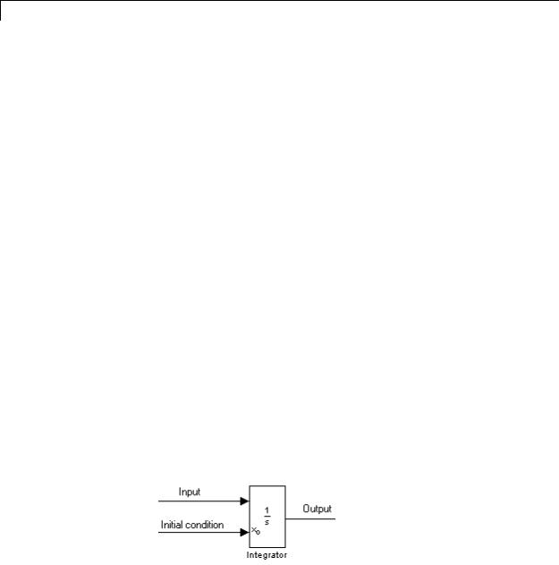
You can define the initial conditions as a parameter on the block dialog box or input them from an external signal:
•To define the initial conditions as a block parameter, specify the
Initial condition source parameter as internal and enter the value in the Initial condition field.
•To provide the initial conditions from an external source, specify the Initial condition source parameter as external. An additional input port appears under the block input.
2-812
Integrator, Integrator Limited
Note If the integrator limits its output (see “Limiting the Integral” on page 2-813), the initial condition must fall inside the integrator’s saturation limits. If the initial condition is outside the block saturation limits, the block displays an error message.
Limiting the Integral
To prevent the output from exceeding specifiable levels, select the Limit output check box and enter the limits in the appropriate parameter fields. This action causes the block to function as a limited integrator. When the output reaches the limits, the integral action is turned off to prevent integral wind up. During a simulation, you can change the limits but you cannot change whether the output is limited. The block determines output as follows:
•When the integral is less than or equal to the Lower saturation limit, the output is held at the Lower saturation limit.
•When the integral is between the Lower saturation limit and the Upper saturation limit, the output is the integral.
•When the integral is greater than or equal to the Upper saturation limit, the output is held at the Upper saturation limit.
To generate a signal that indicates when the state is being limited, select the Show saturation port check box. A saturation port appears below the block output port.
The signal has one of three values:
•1 indicates that the upper limit is being applied.
•0 indicates that the integral is not limited.
2-813

Integrator, Integrator Limited
• –1 indicates that the lower limit is being applied.
When you select this check box, the block has three zero crossings: one to detect when it enters the upper saturation limit, one to detect when it enters the lower saturation limit, and one to detect when it leaves saturation.
Note For the Integrator Limited block, by default, Limit output is selected, Upper saturation limit is set to 1, and Lower saturation limit is set to 0.
Resetting the State
The block can reset its state to the specified initial condition based on an external signal. To cause the block to reset its state, select one of the External reset choices. A trigger port appears below the block’s input port and indicates the trigger type.
•Select rising to reset the state when the reset signal rises from a zero to a positive value or from a negative to a positive value.
•Select falling to reset the state when the reset signal falls from a positive value to zero or from a positive to a negative value.
•Select either to reset the state when the reset signal changes from a zero to a nonzero value or changes sign.
•Select level to reset the state when the reset signal is nonzero at the current time step or changes from nonzero at the previous time step to zero at the current time step.
•Select level hold to reset the state when the reset signal is nonzero at the current time step.
2-814
Integrator, Integrator Limited
The reset port has direct feedthrough. If the block output feeds back into this port, either directly or through a series of blocks with direct feedthrough, an algebraic loop results (see “Algebraic Loops”). Use the Integrator block’s state port to feed back the block’s output without creating an algebraic loop.
Note To be compliant with the Motor Industry Software Reliability Association (MISRA®) software standard, your model must use Boolean signals to drive the external reset ports of Integrator blocks.
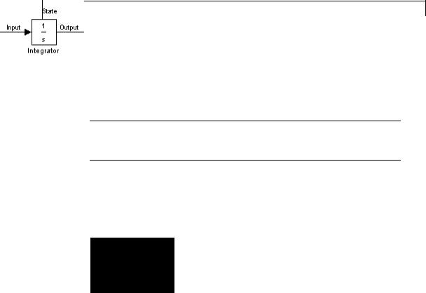
About the State Port
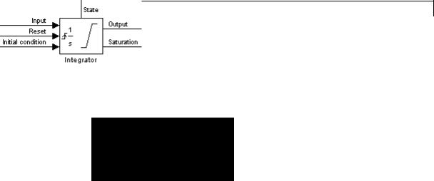
Selecting the Show state port check box on the Integrator block’s parameter dialog box causes an additional output port, the state port, to appear at the top of the Integrator block.
The output of the state port is the same as the output of the block’s standard output port except for the following case. If the block is reset in the current time step, the output of the state port is the value that would have appeared at the block’s standard output if the block had not been reset. The state port’s output appears earlier in the time step than the output of the Integrator block’s output port. Use the state port to avoid creating algebraic loops in these modeling scenarios:
•Self-resetting integrators (see “Creating Self-Resetting Integrators” on page 2-816)
•Handing off a state from one enabled subsystem to another (see “Handing Off States Between Enabled Subsystems” on page 2-818)
2-815
Integrator, Integrator Limited
Note When updating a model, Simulink checks that the state port applies to one of these two scenarios. If not, an error message appears. Also, you cannot log the output of this port in a referenced model that executes in Accelerator mode. If logging is enabled for the port, Simulink generates a "signal not found" warning during execution of the referenced model.
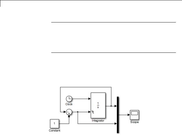
Creating Self-Resetting Integrators
The Integrator block’s state port helps you avoid an algebraic loop when creating an integrator that resets itself based on the value of its output. Consider, for example, the following model.
This model tries to create a self-resetting integrator by feeding the integrator’s output, subtracted from 1, back into the integrator’s reset port. However, the model creates an algebraic loop. To compute the integrator block’s output, Simulink software needs to know the value of the block’s reset signal, and vice versa. Because the two values are mutually dependent, Simulink software cannot determine either. Therefore, an error message appears if you try to simulate or update this model.
2-816
Integrator, Integrator Limited
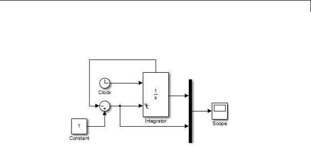
The following model uses the integrator’s state port to avoid the algebraic loop.
In this version, the value of the reset signal depends on the value of the state port. The value of the state port is available earlier in the current time step than the value of the integrator block’s output port. Therefore, Simulink can determine whether the block needs to be reset before computing the block’s output, thereby avoiding the algebraic loop.
2-817

Integrator, Integrator Limited
Handing Off States Between Enabled Subsystems
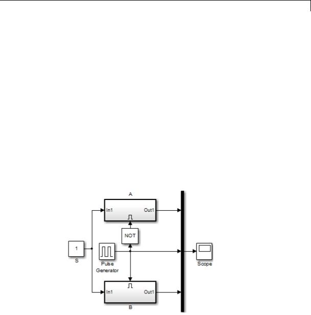
The state port helps you avoid an algebraic loop when passing a state between two enabled subsystems. Consider, for example, the following model.
The enabled subsystems, A and B, contain the following blocks:
Subsystem A |
Subsystem B |
|
|
2-818
Integrator, Integrator Limited
In this model, a constant input signal drives two enabled subsystems that integrate the signal. A pulse generator generates an enabling signal that causes execution to alternate between the two subsystems. The enable port of each subsystem is set to reset, which causes the subsystem to reset its integrator when it becomes active. Resetting the integrator causes the integrator to read the value of its initial condition port. The initial condition port of the integrator in each subsystem is connected to the output port of the integrator in the other subsystem.
This connection is intended to enable continuous integration of the input signal as execution alternates between two subsystems. However, the connection creates an algebraic loop. To compute the output of A, Simulink needs to know the output of B, and vice versa. Because the outputs are mutually dependent, Simulink cannot compute the output values. Therefore, an error message appears if you try to simulate or update this model.
The following version of the same model uses the integrator state port to avoid creating an algebraic loop when handing off the state.
2-819

Integrator, Integrator Limited
The enabled subsystems, A and B, contain the following blocks:
Subsystem A |
Subsystem B |
|
|
In this model, the initial condition of the integrator in A depends on the value of the state port of the integrator in B, and vice versa. The values of the state ports are updated earlier in the simulation time step than the values of the integrator output ports. Therefore, Simulink can compute the initial condition of either integrator without knowing the final output value of the other integrator. For another example of using the state port to hand off states between conditionally executed subsystems, see the sldemo_clutch model.
Note Simulink does not permit three or more enabled subsystems to hand off a model state. If Simulink detects that a model is handing off a state among more than two enabled subsystems, it generates an error.
Specifying the Absolute Tolerance for the Block Outputs
By default Simulink software uses the absolute tolerance value specified in the Configuration Parameters dialog box (see “Specifying Error Tolerances for Variable-Step Solvers”) to compute the output of the Integrator block. If this value does not provide sufficient error control, specify a more appropriate value in the Absolute tolerance
2-820
Integrator, Integrator Limited
Data Type
Support
field of the Integrator block dialog box. The value that you specify is used to compute all the block outputs.
Selecting All Options
When you select all options, the block icon looks like this.
The Integrator block accepts and outputs signals of type double on its data ports. The external reset port accepts signals of type double
or Boolean.
2-821
Integrator, Integrator Limited
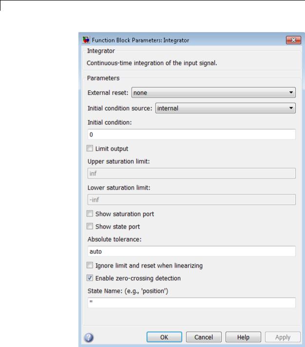
Parameters and
2-822Dialog Box
Integrator, Integrator Limited
External reset
Reset the states to their initial conditions when a trigger event occurs in the reset signal.
Settings
Default: none
none
Do not reset the state to initial conditions.
rising
Reset the state when the reset signal rises from a zero to a positive value or from a negative to a positive value.
falling
Reset the state when the reset signal falls from a positive value to zero or from a positive to a negative value.
either
Reset the state when the reset signal changes from a zero to a nonzero value or changes sign.
level
Reset the state when the reset signal is nonzero at the current time step or changes from nonzero at the previous time step to zero at the current time step.
level hold
Reset the state when the reset signal is nonzero at the current time step.
Command-Line Information
See “Block-Specific Parameters” on page 8-109 for the command-line information.
2-823

Integrator, Integrator Limited
Initial condition source
Get the initial conditions of the states.
Settings
Default: internal
internal
Get the initial conditions of the states from the Initial condition parameter.
external
Get the initial conditions of the states from an external block.
Tips
Simulink software does not allow the initial condition of this block to be inf or NaN.
Dependencies
Selecting internal enables the Initial condition parameter. Selecting external disables the Initial condition parameter.
Command-Line Information
See “Block-Specific Parameters” on page 8-109 for the command-line information.
2-824

Integrator, Integrator Limited
Initial condition
Specify the states’ initial conditions.
Settings
Default: 0
Tips
Simulink software does not allow the initial condition of this block to be inf or NaN.
Dependencies
Setting Initial condition source to internal enables this parameter. Setting Initial condition source to external disables this parameter.
Command-Line Information
See “Block-Specific Parameters” on page 8-109 for the command-line information.
2-825

Integrator, Integrator Limited
Limit output
Limit the block’s output to a value between the Lower saturation limit and Upper saturation limit parameters.
Settings
Default: Off
 On
On
Limit the block’s output to a value between the Lower saturation limit and Upper saturation limit parameters.
 Off
Off
Do not limit the block’s output to a value between the Lower saturation limit and Upper saturation limit parameters.
Dependencies
This parameter enables Upper saturation limit.
This parameter enables Lower saturation limit.
Command-Line Information
See “Block-Specific Parameters” on page 8-109 for the command-line information.
2-826

Integrator, Integrator Limited
Upper saturation limit
Specify the upper limit for the integral.
Settings
Default: inf
Minimum: value of Output minimum parameter
Maximum: value of Output maximum parameter
Dependencies
Limit output enables this parameter.
Command-Line Information
See “Block-Specific Parameters” on page 8-109 for the command-line information.
2-827

Integrator, Integrator Limited
Lower saturation limit
Specify the lower limit for the integral.
Settings
Default: -inf
Minimum: value of Output minimum parameter Maximum: value of Output maximum parameter
Dependencies
Limit output enables this parameter.
Command-Line Information
See “Block-Specific Parameters” on page 8-109 for the command-line information.
2-828

Integrator, Integrator Limited
Show saturation port
Add a saturation output port to the block.
Settings
Default: Off
 On
On
Add a saturation output port to the block.
 Off
Off
Do not add a saturation output port to the block.
Command-Line Information
See “Block-Specific Parameters” on page 8-109 for the command-line information.
2-829

Integrator, Integrator Limited
Show state port
Add an output port to the block for the block’s state.
Settings
Default: Off
 On
On
Add an output port to the block for the block’s state.
 Off
Off
Do not add an output port to the block for the block’s state.
Command-Line Information
See “Block-Specific Parameters” on page 8-109 for the command-line information.
2-830

Integrator, Integrator Limited
Absolute tolerance
Specify the absolute tolerance for computing block states.
Settings
Default: auto
•You can enter auto, 1, a real scalar, or a real vector.
•If you enter auto or 1, then Simulink uses the absolute tolerance value in the Configuration Parameters dialog box (see “Solver Pane”) to compute block states.
•If you enter a real scalar, then that value overrides the absolute tolerance in the Configuration Parameters dialog box for computing all block states.
•If you enter a real vector, then the dimension of that vector must match the dimension of the continuous states in the block. These values override the absolute tolerance in the Configuration Parameters dialog box.
Command-Line Information
See “Block-Specific Parameters” on page 8-109 for the command-line information.
2-831

Integrator, Integrator Limited
Ignore limit and reset when linearizing
Cause Simulink linearization commands to treat this block as unresettable and as having no limits on its output, regardless of the settings of the block’s reset and output limitation options.
Settings
Default: Off
 On
On
Cause Simulink linearization commands to treat this block as unresettable and as having no limits on its output, regardless of the settings of the block’s reset and output limitation options.
 Off
Off
Do not cause Simulink linearization commands to treat this block as unresettable and as having no limits on its output, regardless of the settings of the block’s reset and output limitation options.
Tip
Use this check box to linearize a model around an operating point that causes the integrator to reset or saturate.
Command-Line Information
See “Block-Specific Parameters” on page 8-109 for the command-line information.
2-832
Integrator, Integrator Limited
Enable zero-crossing detection
Select to enable zero-crossing detection. For more information, see “Zero-Crossing Detection” in the Simulink documentation.
Settings
Default: On
 On
On
Use zero crossings to detect and take a time step at any of the following events: reset, entering or leaving an upper saturation state, entering or leaving a lower saturation state.
 Off
Off
Do not use zero crossings to detect and take a time step at any of the following events: reset, entering or leaving an upper saturation state, entering or leaving a lower saturation state.
If you select this check box, Limit output, and zero-crossing detection for the model as a whole, the Integrator block uses zero crossings as described.
Command-Line Information
See “Block-Specific Parameters” on page 8-109 for the command-line information.
2-833

Integrator, Integrator Limited
2-834

Integrator, Integrator Limited
State Name (e.g., ’position’)
Assign a unique name to each state.
Settings
Default: ' '
If this field is blank, no name assignment occurs.
Examples
Tips
•To assign a name to a single state, enter the name between quotes, for example, 'velocity'.
•To assign names to multiple states, enter a comma-delimited list surrounded by braces, for example, {'a', 'b', 'c'}. Each name must be unique.
•The state names apply only to the selected block.
•The number of states must divide evenly among the number of state names.
•You can specify fewer names than states, but you cannot specify more names than states.
For example, you can specify two names in a system with four states. The first name applies to the first two states and the second name to the last two states.
•To assign state names with a variable in the MATLAB workspace, enter the variable without quotes. A variable can be a string, cell array, or structure.
Command-Line Information
See “Block-Specific Parameters” on page 8-109 for the command-line information.
The following example models show how to use the Integrator block:
•sldemo_hardstop
•sldemo_suspn
2-835

Integrator, Integrator Limited
|
|
• sldemo_wheelspeed_absbrake |
|
|
Characteristics |
|
|
|
|
|
Direct Feedthrough |
|
Yes, of the reset and external initial |
|
|
|
|
|
condition source ports |
|
|
Sample Time |
|
Continuous |
|
|
Scalar Expansion |
|
Yes, of parameters |
|
|
States |
|
Inherited from driving block or |
|
|
|
|
parameter |
|
|
Dimensionalized |
|
Yes |
|
|
Multidimensionalized |
|
No |
|
|
Zero-Crossing Detection |
|
Yes, if enabled and you select the |
|
|
|
|
Limit output check box, one for |
|
|
|
|
detecting reset, one each to detect |
|
|
|
|
upper and lower saturation limits, |
|
|
|
|
and one when leaving saturation |
|
|
|
|
|
See Also |
Discrete-Time Integrator |
|
||
2-836
Interpolation Using Prelookup
Purpose |
Use precalculated index and fraction values to accelerate approximation |
|
of N-dimensional function |
Library |
Lookup Tables |
Description |
How This Block Works with a Prelookup Block |
|
The Interpolation Using Prelookup block works best with the Prelookup |
|
block. The Prelookup block calculates the index and interval fraction |
|
that specify how its input value u relates to the breakpoint data set. |
|
You feed the resulting index and fraction values into an Interpolation |
|
Using Prelookup block to interpolate an n-dimensional table. This |
|
combination of blocks performs the same operation that a single |
|
instance of the n-D Lookup Table block performs. However, the |
|
Prelookup and Interpolation Using Prelookup blocks offer greater |
|
flexibility that can provide more efficient simulation and code |
|
generation. For more information, see “Efficiency of Performance” in |
|
the Simulink documentation. |
|
Supported Block Operations |
|
To use the Interpolation Using Prelookup block, you specify a set of |
|
table data values directly on the dialog box or feed values into the T |
|
input port. Typically, these table values correspond to the breakpoint |
|
data sets specified in Prelookup blocks. The Interpolation Using |
|
Prelookup block generates output by looking up or estimating table |
|
values based on index and interval fraction values fed from Prelookup |
|
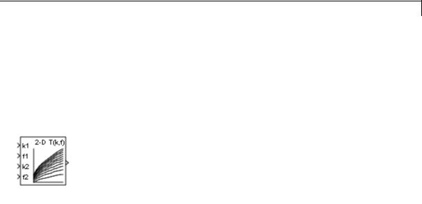
blocks. Labels for the index and interval fraction appear as k and f on |
|
the Interpolation Using Prelookup block icon. |
2-837

Interpolation Using Prelookup
|
When inputs for index and |
The Interpolation Using |
|
|
interval fraction... |
Prelookup block... |
|
|
Map to values in breakpoint data |
Outputs the table value at |
|
|
sets |
the intersection of the row, |
|
|
|
column, and higher dimension |
|
|
|
breakpoints |
|
|
Do not map to values in |
Interpolates appropriate table |
|
|
breakpoint data sets, but |
values, using the Interpolation |
|
|
are within range |
method you select |
|
|
Do not map to values in |
Extrapolates the output value, |
|
|
breakpoint data sets, and |
using the Extrapolation |
|
|
are out of range |
method you select |
|
How The Block Interpolates a Subset of Table Data
You can use the Number of sub-table selection dimensions parameter to specify that interpolation occur only on a subset of the table data. To activate this interpolation mode, set this parameter to a positive integer. This value defines the number of dimensions to select, starting from the highest dimension of table data. Therefore, the value must be less than or equal to the Number of table dimensions.
Suppose that you have 3-D table data in your Interpolation Using Prelookup block. The following behavior applies.
|
Number of |
Action by the Block |
Block Appearance |
|
|
Selection |
|
|
|
|
Dimensions |
|
|
|
|
0 |
Interpolates the entire |
Does not change |
|
|
|
table and does not |
|
|
|
|
activate subtable |
|
|
|
|
selection |
|
|
|
1 |
Interpolates the first |
Displays an input port |
|
|
|
two dimensions and |
with the label sel1 that |
|
2-838

Interpolation Using Prelookup
Data Type
Support
Number of |
Action by the Block |
Block Appearance |
Selection |
|
|
Dimensions |
|
|
|
|
|
|
selects the third |
you use to select and |
|
dimension |
interpolate 2-D tables |
2 |
Interpolates the first |
Displays two input |
|
dimension and selects |
ports with the labels |
|
the second and third |
sel1 and sel2 that |
|
dimensions |
you use to select and |
|
|
interpolate 1-D tables |
Subtable selection uses zero-based indexing. For an example of interpolating a subset of table data, type sldemo_bpcheck at the MATLAB command prompt.
The Interpolation Using Prelookup block accepts real signals of any numeric data type supported by Simulink software, except Boolean. The Interpolation Using Prelookup block supports fixed-point data types for signals, table data, and intermediate results.
For more information, see “Data Types Supported by Simulink” in the Simulink documentation.
2-839

Interpolation Using Prelookup
Parameters |
The Main pane of the Interpolation Using Prelookup block dialog box |
and |
appears as follows: |
Dialog |
|
Box |
|
Number of table dimensions
Specify the number of dimensions that the table data must have. This value defines the number of independent variables for the table. Enter an integer between 1 and 30 into this field.
2-840

Interpolation Using Prelookup
Table data
Specify whether to enter table data directly on the dialog box or to inherit the data from an input port.
•If you set Source to Dialog, enter table data in the edit field under Value. The size of the table data must match the Number of table dimensions. For this option, you specify table attributes on the Data Types pane.
•If you set Source to Input port, verify that an upstream signal supplies table data to the T input port. The size of the table data must match the Number of table dimensions. For this option, your block inherits table attributes from the T input port.
During block diagram editing, you can enter an empty matrix (specified as []) or an undefined workspace variable in the edit field under Value. Use this behavior to postpone specifying a correctly dimensioned matrix for the table data and continue editing the block diagram. For information about how to construct multidimensional arrays in MATLAB, see “Multidimensional Arrays” in the MATLAB documentation.
Click the Edit button to open the Lookup Table Editor (see “Edit Existing LookupTables” in the Simulink documentation).
Interpolation method
Select Flat or Linear. See “Interpolation Methods” in the Simulink documentation for more information.
Extrapolation method
Select Clip or Linear. See “Extrapolation Methods” in the Simulink documentation for more information. The
Extrapolation method parameter is visible only when you select Linear as the Interpolation method parameter.
The Interpolation Using Prelookup block does not support Linear extrapolation when the input or output signals specify integer or fixed-point data types.
2-841

Interpolation Using Prelookup
Valid index input may reach last index
Specify how block inputs for index (k) and interval fraction (f) access the last elements of n-dimensional table data. Index values are zero-based.
|
Check Box |
Block Behavior |
|
|
Selected |
Returns the value of the last element in a |
|
|
|
dimension of its table when: |
|
|
|
• k indexes the last table element in the |
|
|
|
corresponding dimension |
|
|
|
• f is 0 |
|
|
Cleared |
Returns the value of the last element in a |
|
|
|
dimension of its table when: |
|
|
|
• k indexes the next-to-last table element in |
|
|
|
the corresponding dimension |
|
|
|
• f is 1 |
|
|
|
|
|
This check box is visible only when:
•Interpolation method is Linear.
•Extrapolation method is Clip.
Tip When you select Valid index input may reach last index for an Interpolation Using Prelookup block, you must also select
Use last breakpoint for input at or above upper limit for all Prelookup blocks that feed it. This action allows the blocks to use the same indexing convention when accessing the last elements of their breakpoint and table data sets.
2-842
Interpolation Using Prelookup
Diagnostic for out-of-range input
Specify whether to produce a warning or error when the input k or f is out of range. Options include:
•None — no warning or error
•Warning — display a warning in the MATLAB Command Window and continue the simulation
•Error — halt the simulation and display an error in the Simulation Diagnostics Viewer
Remove protection against out-of-range index in generated code
Specify whether or not to include code that checks for out-of-range index inputs.
|
Check Box |
Result |
When to Use |
|
|
Selected |
Generated code |
For code efficiency |
|
|
|
does not include |
|
|
|
|
conditional |
|
|
|
|
statements to check |
|
|
|
|
for out-of-range |
|
|
|
|
index inputs. |
|
|
|
Cleared |
Generated code |
For safety-critical |
|
|
|
includes conditional |
applications |
|
|
|
statements to check |
|
|
|
|
for out-of-range |
|
|
|
|
index inputs. |
|
|
Depending on your application, you can run the following Model Advisor checks to verify the usage of this check box:
•By Product > Embedded Coder > Identify lookup table blocks that generate expensive out-of-range checking code
2-843

Interpolation Using Prelookup
•By Product > Simulink Verification and Validation > Modeling Standards > DO-178C/DO-331 Checks > Check usage of lookup table blocks
For more information about the Model Advisor, see “Consult the Model Advisor” in the Simulink documentation.
This check box has no effect on generated code when one of the following is true:
•The Prelookup block feeds index values to the Interpolation Using Prelookup block.
Because index values from the Prelookup block are always valid, no check code is necessary.
•The data type of the input k restricts the data to valid index values.
For example, unsigned integer data types guarantee nonnegative index values. Therefore, unsigned input values of k do not require check code for negative values.
Number of sub-table selection dimensions
Specify the number of dimensions of the subtable that the block uses to compute the output. Follow these rules:
•To enable subtable selection, enter a positive integer.
This integer must be less than or equal to the Number of table dimensions.
•To disable subtable selection, enter 0 to interpolate the entire table.
For more information, see “How The Block Interpolates a Subset of Table Data” on page 2-838.
2-844
Interpolation Using Prelookup
Sample time
Specify the time interval between samples. To inherit the sample time, set this parameter to -1. See “Specify Sample Time” in the Simulink documentation for more information.
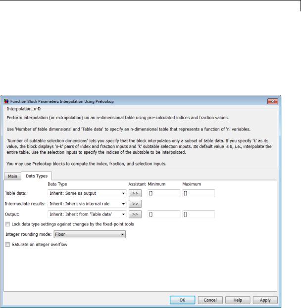
The Data Types pane of the Interpolation Using Prelookup block dialog box appears as follows:
2-845

Interpolation Using Prelookup
Note The parameters for table attributes (data type, minimum, and maximum) are not available when you set Source to Input port. In this case, the block inherits all table attributes from the T input port.
Table data > Data Type
Specify the table data type. You can set it to:
•A rule that inherits a data type, for example, Inherit: Same as output
•The name of a built-in data type, for example, single
•The name of a data type object, for example, a
Simulink.NumericType object
•An expression that evaluates to a data type, for example, fixdt(1,16,0)
Click the Show data type assistant button  to display the Data Type Assistant, which helps you set the table data type.
Tip Specify a table data type different from the output data type for these cases:
•Lower memory requirement for storing table data that uses a smaller type than the output signal
•Sharing of prescaled table data between two Interpolation Using Prelookup blocks with different output data types
•Sharing of custom storage table data in Simulink Coder generated code for blocks with different output data types
2-846

Interpolation Using Prelookup
Table data > Minimum
Specify the minimum value for table data. The default value is [] (unspecified).
Table data > Maximum
Specify the maximum value for table data. The default value is [] (unspecified).
Intermediate results > Data Type
Specify the intermediate results data type. You can set it to:
•A rule that inherits a data type, for example, Inherit: Same as output
•The name of a built-in data type, for example, single
•The name of a data type object, for example, a
Simulink.NumericType object
•An expression that evaluates to a data type, for example, fixdt(1,16,0)
Click the Show data type assistant button  to display the Data Type Assistant, which helps you set the intermediate results data type.
Tip Use this parameter to specify higher precision for internal computations than for table data or output data.
Output > Data Type
Specify the output data type. You can set it to:
•A rule that inherits a data type, for example, Inherit: Inherit via back propagation
•The name of a built-in data type, for example, single
•The name of a data type object, for example, a
Simulink.NumericType object
2-847

Interpolation Using Prelookup
•An expression that evaluates to a data type, for example, fixdt(1,16,0)
Click the Show data type assistant button  to display the Data Type Assistant, which helps you set the output data type.
See “Specify Block Output Data Types” in the Simulink User’s Guide for more information.
Output > Minimum
Specify the minimum value that the block should output. The default value is [] (unspecified). Simulink software uses this value to perform:
•Parameter range checking (see “Check Parameter Values”)
•Simulation range checking (see “Signal Ranges”)
•Automatic scaling of fixed-point data types
Output > Maximum
Specify the maximum value that the block should output. The default value is [] (unspecified). Simulink software uses this value to perform:
•Parameter range checking (see “Check Parameter Values”)
•Simulation range checking (see “Signal Ranges”)
•Automatic scaling of fixed-point data types
Lock data type settings against changes by the fixed-point tools
Select to lock all data type settings of this block against changes by the Fixed-Point Tool and the Fixed-Point Advisor. For more information, see “Locking the Output Data Type Setting”in the Simulink Fixed Point documentation.
2-848

Interpolation Using Prelookup
Integer rounding mode
Specify the rounding mode for fixed-point operations. For more information, see “Rounding” in the Simulink Fixed Point documentation.
Block parameters always round to the nearest representable value. To control the rounding of a block parameter, enter an expression using a MATLAB rounding function in the mask field.
Saturate on integer overflow
|
Action |
Reasons for Taking |
What Happens for |
Example |
|
|
This Action |
Overflows |
|
|
Select this |
Your model has |
Overflows saturate to |
An overflow associated |
|
check box. |
possible overflow, |
either the minimum |
with a signed 8-bit |
|
|
and you want explicit |
or maximum value |
integer can saturate to |
|
|
saturation protection |
that the data type can |
–128 or 127. |
|
|
in the generated code. |
represent. |
|
|
Do not select |
You want to optimize |
Overflows wrap to the |
The number 130 does |
|
this check |
efficiency of your |
appropriate value that |
not fit in a signed 8-bit |
|
box. |
generated code. |
is representable by the |
integer and wraps to |
|
|
You want to avoid |
data type. |
–126. |
|
|
|
|
|
|
|
overspecifying how |
|
|
|
|
a block handles |
|
|
|
|
out-of-range signals. |
|
|
|
|
For more information, |
|
|
|
|
see “Checking for |
|
|
|
|
Signal Range Errors”. |
|
|
|
|
When you select this check box, saturation applies to every |
||
|
|
internal operation on the block, not just the output or result. |
||
|
|
Usually, the code generation process can detect when overflow is |
||
|
|
not possible. In this case, the code generator does not produce |
||
|
|
saturation code. |
|
|
2-849
Interpolation Using Prelookup
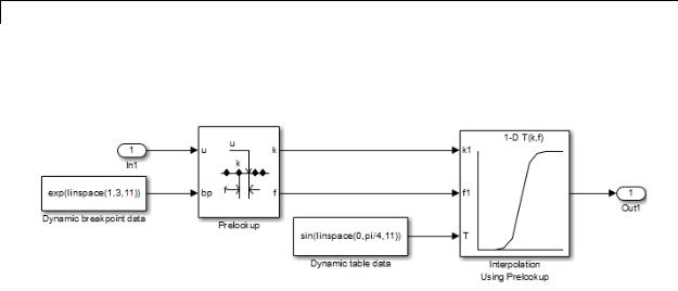
Examples
In the following model, a Constant block feeds the table data values to the T input port of the Interpolation Using Prelookup block.
The Interpolation Using Prelookup block inherits the following table attributes from the T input port:
|
Table Attribute |
Value |
|
|
Minimum |
–Inf |
|
|
Maximum |
Inf |
|
|
Data type |
single |
|
|
|
|
|
Similarly, a Constant block feeds the breakpoint data set to the bp input port of the Prelookup block, which inherits the following breakpoint attributes:
|
Breakpoint Attribute |
Value |
|
|
Minimum |
–Inf |
|
|
Maximum |
Inf |
|
|
Data type |
single |
|
|
|
|
|
Simulink uses double-precision, floating-point data to perform the computations in this model. However, the model stores the breakpoint and table data as single-precision, floating-point data. Using a
2-850

Interpolation Using Prelookup
lower-precision data type to store breakpoint and table data reduces the memory requirement.
For other examples, see “Prelookup and Interpolation Blocks” in the Simulink documentation.
Characteristics |
|
Direct Feedthrough |
Yes |
|
|
Sample Time |
Specified in the Sample time |
|
|
|
parameter |
|
|
Scalar Expansion |
Yes |
|
|
Dimensionalized |
Yes |
|
|
Zero-Crossing Detection |
No |
See Also |
|
Prelookup |
|
2-851

Interpreted MATLAB Function
Purpose
Library
Description
Data Type
Support
Apply MATLAB function or expression to input
User-Defined Functions
The Interpreted MATLAB Function block applies the specified MATLAB function or expression to the input. The output of the function must match the output dimensions of the block or an error occurs.
Some valid expressions for this block are:
sin
atan2(u(1), u(2)) u(1)^u(2)
Note This block is slower than the Fcn block because it calls the MATLAB parser during each integration step. Consider using built-in blocks (such as the Fcn block or the Math Function block) instead. Alternatively, you can write the function as a MATLAB S-function or MEX-file S-function, then access it using the S-Function block.
The Interpreted MATLAB Function block accepts one real or complex input of type double and generates real or complex output of type double, depending on the setting of the Output signal type parameter.
2-852
Interpreted MATLAB Function
Parameters and Dialog Box
MATLAB function
Specify the function or expression. If you specify a function only, it is not necessary to include the input argument in parentheses.
2-853

Interpreted MATLAB Function
Output dimensions
Specify the dimensions of the signal output by this block. If the output dimensions are to be the same as the dimensions of the input signal, specify –1. Otherwise, enter the dimensions of the output signal, for example, 2 for a two-element vector. In either case, the output dimensions must match the dimensions of the value returned by the function or expression in the MATLAB function field.
Output signal type
Specify the output signal type of the block as real, complex, or auto. A value of auto sets the output type to be the same as the type of the input signal.
Collapse 2-D results to 1-D
Select this check box to output a 2-D array as a 1-D array containing the 2-D array’s elements in column-major order.
Sample time (-1 for inherited)
Specify the time interval between samples. To inherit the sample time, set this parameter to -1. See “Specify Sample Time” in the online documentation for more information.
Characteristics |
Direct Feedthrough |
Yes |
|
Sample Time |
Inherited from the driving block |
|
Scalar Expansion |
N/A |
|
Dimensionalized |
Yes |
|
Zero-Crossing Detection |
No |
|
|
|
2-854

Interval Test
Purpose |
Determine if signal is in specified interval |
Library |
Logic and Bit Operations |
Description |
The Interval Test block outputs TRUE if the input is between the values |
|
specified by the Lower limit and Upper limit parameters. The block |
|
outputs FALSE if the input is outside those values. The output of the |
|
block when the input is equal to the Lower limit or the Upper limit is |
|
determined by whether the boxes next to Interval closed on left and |
|
Interval closed on right are selected in the dialog box. |
Data Type
Support
The Interval Test block accepts signals of the following data types:
•Floating point
•Built-in integer
•Fixed point
•Boolean
•Enumerated
In this case, the Upper limit and Lower limit values must be of the same enumerated type.
For more information, see “Data Types Supported by Simulink” in the Simulink documentation.
2-855
Interval Test
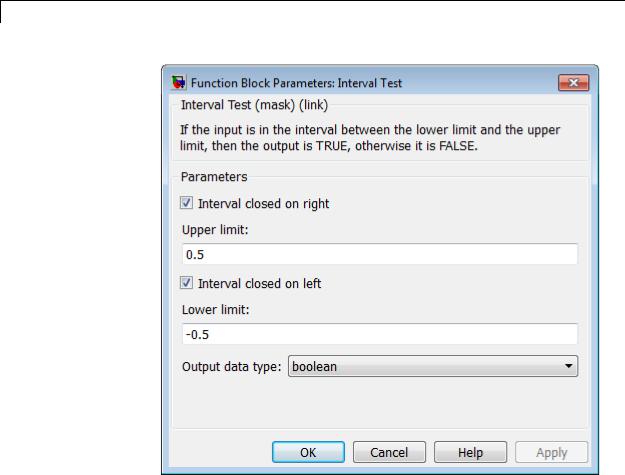
Parameters and Dialog Box
Interval closed on right
When you select this check box, the Upper limit is included in the interval for which the block outputs TRUE.
Upper limit
The upper limit of the interval for which the block outputs TRUE.
Interval closed on left
When you select this check box, the Lower limit is included in the interval for which the block outputs TRUE.
2-856

Interval Test
Lower limit
The lower limit of the interval for which the block outputs TRUE.
Output data type
Select the output data type: boolean or uint8.
Characteristics
See Also
Direct Feedthrough |
Yes |
Scalar Expansion |
Yes |
Zero-Crossing Detection |
No |
|
|
Interval Test Dynamic
2-857

Interval Test Dynamic
Purpose |
Determine if signal is in specified interval |
Library |
Logic and Bit Operations |
Description |
The Interval Test Dynamic block outputs TRUE if the input is between |
|
the values of the external signals up and lo. The block outputs FALSE |
|
if the input is outside those values. The output of the block when the |
|
input is equal to the signal up or the signal lo is determined by whether |
|
the boxes next to Interval closed on left and Interval closed on |
|
right are selected in the dialog box. |
Data Type
Support
The Interval Test Dynamic block accepts signals of the following data types:
•Floating point
•Built-in integer
•Fixed point
•Boolean
•Enumerated
In this case, all inputs must be of the same enumerated type.
For more information, see “Data Types Supported by Simulink” in the Simulink documentation.
2-858

Interval Test Dynamic
Parameters and Dialog Box
Interval closed on right
When you select this check box, the value of the signal connected to the block’s “up” input port is included in the interval for which the block outputs TRUE.
Interval closed on left
When you select this check box, the value of the signal connected to the block’s “lo” input port is included in the interval for which the block outputs TRUE.
Output data type
Select the output data type: boolean or uint8.
Characteristics |
Direct Feedthrough |
Yes |
|
Scalar Expansion |
Yes |
|
Zero-Crossing Detection |
No |
|
|
|
2-859

Interval Test Dynamic
See Also |
Interval Test |
2-860

Level-2 MATLAB S-Function
Purpose
Library
Description
Data Type
Support
Use Level-2 MATLAB S-function in model
User-Defined Functions
This block allows you to use a Level-2 MATLAB S-function (see “Write Level-2 MATLAB S-Functions”) in a model. To do this, create an instance of this block in the model. Then enter the name of the Level-2 MATLAB S-function in the S-function name field of the block’s parameter dialog box.
Note Use the S-Function block to include a Level-1 MATLAB S-function in a block.
If the Level-2 MATLAB S-function defines any additional parameters, you can enter them in the Parameters field of the block’s parameter dialog box. Enter the parameters as MATLAB expressions that evaluate to their values in the order defined by the MATLAB S-function. Use commas to separate each expression.
If a model includes a Level-2 MATLAB S-Function block, and an error occurs in the S-function, the Level-2 MATLAB S-Function block displays MATLAB stack trace information for the error in a dialog box. Click OK to close the dialog box.
Depends on the MATLAB file that defines the behavior of a particular instance of this block.
2-861

Level-2 MATLAB S-Function
Parameters and Dialog Box
S-function name
Specify the name of a MATLAB function that defines the behavior of this block. The MATLAB function must follow the Level-2 standard for writing MATLAB S-functions (see “Write Level-2 MATLAB S-Functions” for details).
Parameters
Specify values of the parameters of this block.
Characteristics |
Direct Feedthrough |
Depends on the MATLAB S-function |
|
Sample Time |
Depends on the MATLAB S-function |
|
Scalar Expansion |
Depends on the MATLAB S-function |
|
Dimensionalized |
Depends on the MATLAB S-function |
|
Multidimensionalized |
Yes |
|
Zero Crossing |
No |
|
|
|
2-862
Logical Operator
Purpose
Library
Description
Perform specified logical operation on input
Logic and Bit Operations
The Logical Operator block performs the specified logical operation on its inputs. An input value is TRUE (1) if it is nonzero and FALSE
(0) if it is zero.
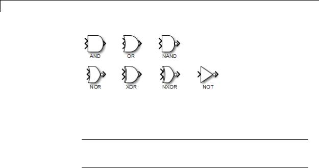
You select the Boolean operation connecting the inputs with the Operator parameter list. If you select rectangular as the Icon shape property, the block updates to display the name of the selected operator. The supported operations are given below.
|
Operation |
Description |
|
|
AND |
TRUE if all inputs are TRUE |
|
|
OR |
TRUE if at least one input is TRUE |
|
|
NAND |
TRUE if at least one input is FALSE |
|
|
NOR |
TRUE when no inputs are TRUE |
|
|
XOR |
TRUE if an odd number of inputs are TRUE |
|
|
NXOR |
TRUE if an even number of inputs are TRUE |
|
|
NOT |
TRUE if the input is FALSE |
|
|
|
|
|
If you select distinctive as the Icon shape, the block’s appearance indicates its function. Simulink software displays a distinctive shape for the selected operator, conforming to the IEEE Standard Graphic Symbols for Logic Functions:
2-863
Logical Operator
The number of input ports is specified with the Number of input ports parameter. The output type is specified with the Output data type parameter. An output value is 1 if TRUE and 0 if FALSE.
Note The output data type should represent zero exactly. Data types that satisfy this condition include signed and unsigned integers, and any floating-point data type.
The size of the output depends on input vector size and the selected operator:
•If the block has more than one input, any nonscalar inputs must have the same dimensions. For example, if any input is a 2-by-2 array, all other nonscalar inputs must also be 2-by-2 arrays.
Scalar inputs are expanded to have the same dimensions as the nonscalar inputs.
If the block has more than one input, the output has the same dimensions as the inputs (after scalar expansion) and each output element is the result of applying the specified logical operation to the corresponding input elements. For example, if the specified operation is AND and the inputs are 2-by-2 arrays, the output is a 2-by-2 array whose top left element is the result of applying AND to the top left elements of the inputs, etc.
2-864
Logical Operator
Data Type
Support
•For a single vector input, the block applies the operation (except the NOT operator) to all elements of the vector. The output is always a scalar.
•The NOT operator accepts only one input, which can be a scalar or a vector. If the input is a vector, the output is a vector of the same size containing the logical complements of the input vector elements.
When configured as a multi-input XOR gate, this block performs an addition- modulo-two operation as mandated by the IEEE Standard for Logic Elements.
The Logical Operator block accepts real signals of any numeric data type that Simulink supports, including fixed-point data types.
For more information, see “Data Types Supported by Simulink” in the Simulink documentation.
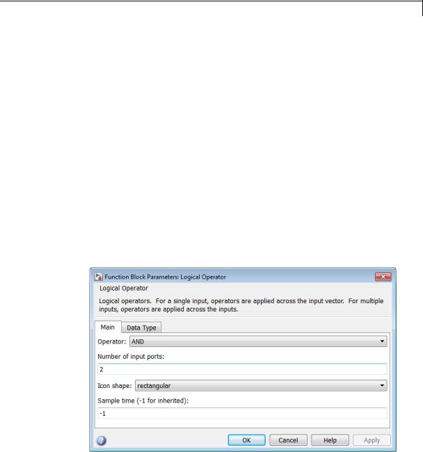
Parameters |
The Main pane of the Logical Operator block dialog box appears as |
and |
follows: |
Dialog |
|
Box |
|
2-865
Logical Operator
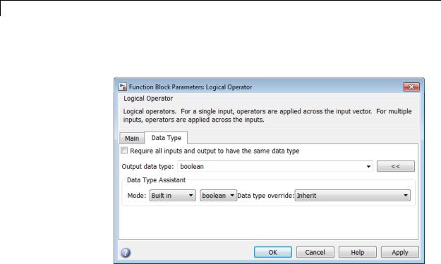
The Data Type pane of the Logical Operator block dialog box appears as follows:
2-866

Logical Operator
Show data type assistant
Display the Data Type Assistant.
Settings
The Data Type Assistant helps you set the Output data type parameter.
For more information, see “Specify Block Output Data Types”.
Command-Line Information
See “Block-Specific Parameters” on page 8-109 for the command-line information.
2-867

Logical Operator
Operator
Select logical operator to apply to block inputs.
Settings
Default: AND
AND
TRUE if all inputs are TRUE
OR
TRUE if at least one input is TRUE
NAND
TRUE if at least one input is FALSE
NOR
TRUE when no inputs are TRUE
XOR
TRUE if an odd number of inputs are TRUE
NXOR
TRUE if an even number of inputs are TRUE
NOT
TRUE if the input is FALSE
Command-Line Information
See “Block-Specific Parameters” on page 8-109 for the command-line information.
2-868

Logical Operator
Number of input ports
Specify number of block inputs.
Settings
Default: 2
• The value must be appropriate for the selected operator.
Command-Line Information
See “Block-Specific Parameters” on page 8-109 for the command-line information.
2-869

Logical Operator
Icon shape
Specify shape of the block icon.
Settings
Default: rectangular
rectangular
Result in a rectangular block that displays the name of the selected operator.
distinctive
Use the graphic symbol for the selected operator as specified by the IEEE standard.
Command-Line Information
See “Block-Specific Parameters” on page 8-109 for the command-line information.
2-870

Logical Operator
Sample time (-1 for inherited)
Enter the discrete interval between sample time hits or specify another appropriate sample time such as continuous or inherited.
Settings
Default: -1
By default, the block inherits its sample time based upon the context of the block within the model. To set a different sample time, enter a valid sample time based upon the table in “Types of Sample Time”.
See also “Specify Sample Time” in the online documentation for more information.
Command-Line Information
See “Block-Specific Parameters” on page 8-109 for the command-line information.
2-871

Logical Operator
Require all inputs and output to have the same data type
Require all inputs and the output to have the same data type.
Settings
Default: Off
 On
On
Require all inputs and the output to have the same data type.
 Off
Off
Do not require all inputs and the output to have the same data type.
Command-Line Information
See “Block-Specific Parameters” on page 8-109 for the command-line information.
2-872
Logical Operator
Output data type
Specify the output data type.
Settings
Default: boolean
Inherit: Logical (see Configuration Parameters:
Optimization)
Uses the Implement logic signals as Boolean data configuration parameter (see “Implement logic signals as Boolean data (vs. double)”) to specify the output data type.
Note This option supports models created before the boolean option was available. Use one of the other options, preferably boolean, for new models.
boolean
Specifies output data type is boolean.
fixdt(1,16)
Specifies output data type is fixdt(1,16).
<data type expression>
Uses the name of a data type object, for example,
Simulink.NumericType.
Tip To enter a built-in data type (double, single, int8, uint8, int16, uint16, int32, or uint32), enclose the expression in single quotes. For example, enter 'double' instead of double.
Command-Line Information
See “Block-Specific Parameters” on page 8-109 for the command-line information.
2-873

Logical Operator
Mode
Select the category of data to specify.
Settings
Default: Built in
Inherit
Specifies inheritance rules for data types. Selecting Inherit
enables Logical (see Configuration Parameters:
Optimization).
Built in
Specifies built-in data types. Selecting Built in enables boolean.
Fixed point
Specifies fixed-point data types.
Expression
Specifies expressions that evaluate to data types.
Dependency
Clicking the Show data type assistant button enables this parameter.
Command-Line Information
See “Block-Specific Parameters” on page 8-109 for the command-line information.
See Also
See “Specify Data Types Using Data Type Assistant”.
2-874

Logical Operator
Data type override
Specify data type override mode for this signal.
Settings
Default: Inherit
Inherit
Inherits the data type override setting from its context, that is, from the block, Simulink.Signal object or Stateflow chart in Simulink that is using the signal.
Off
Ignores the data type override setting of its context and uses the fixed-point data type specified for the signal.
Tip
The ability to turn off data type override for an individual data type provides greater control over the data types in your model when you apply data type override. For example, you can use this option to ensure that data types meet the requirements of downstream blocks regardless of the data type override setting.
Dependency
This parameter appears only when the Mode is Built in or Fixed point.
2-875

Logical Operator
Signedness
Specify whether you want the fixed-point data as signed or unsigned.
Settings
Default: Signed
Signed
Specify the fixed-point data as signed.
Unsigned
Specify the fixed-point data as unsigned.
Dependencies
Selecting Mode > Fixed point enables this parameter.
Command-Line Information
See “Block-Specific Parameters” on page 8-109 for the command-line information.
See Also
For more information, see “Specifying a Fixed-Point Data Type”.
2-876

Logical Operator
Word length
Specify the bit size of the word that holds the quantized integer.
Settings
Default: 16
Minimum: 0
Maximum: 32
Dependencies
Selecting Mode > Fixed point enables this parameter.
Command-Line Information
See “Block-Specific Parameters” on page 8-109 for the command-line information.
See Also
For more information, see “Specifying a Fixed-Point Data Type”.
2-877

Logical Operator
Scaling
Specify the method for scaling your fixed-point data to avoid overflow conditions and minimize quantization errors.
Settings
Default: Integer
Integer
Specify integer. This setting has the same result as specifying a binary point location and setting fraction length to 0.
Command-Line Information
See “Block-Specific Parameters” on page 8-109 for the command-line information.
See Also
See “Specifying a Fixed-Point Data Type”.
2-878

Logical Operator
Examples Logical Operator Block: AND Operator
In the sldemo_fuelsys model, the fuel_rate_control/airflow_calc subsystem uses a Logical Operator block as an AND operator:
The output of the Logical Operator block (the enable_integration signal) feeds into the control port of a Switch block that activates feedback control.
|
When the Logical Operator |
Feedback control... |
|
|
block output is... |
|
|
|
1 |
Occurs |
|
|
0 |
Does not occur |
|
|
|
|
|
2-879
Logical Operator
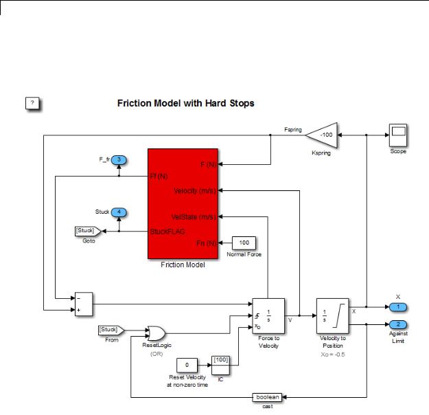
Logical Operator Block: OR Operator
In the sldemo_hardstop model, the Logical Operator block appears as an OR operator:
2-880

Logical Operator
The output of the Logical Operator block feeds into the trigger port of an Integrator block to control whether velocity resets to the initial condition.
|
When the Logical Operator |
The Integrator block... |
|
|
block output changes... |
|
|
|
From 0 to 1 |
Resets the velocity |
|
|
From 1 to 0 |
Does not reset velocity |
|
|
|
|
|
2-881

Logical Operator
Logical Operator Block: NOT Operator
In the sldemo_clutch model, the Logical Operator block appears as a NOT operator:
2-882
Logical Operator
The output of the Logical Operator block (the clutch slipping signal) feeds into the trigger port of an enabled subsystem.
|
When the Logical Operator |
The Unlocked subsystem is... |
|
|
block outputs... |
|
|
|
1 |
Enabled |
|
|
0 |
Disabled |
|
Characteristics |
|
|
|
Direct Feedthrough |
Yes |
|
|
|
Sample Time |
Specified in the Sample time |
|
|
|
parameter |
|
|
Scalar Expansion |
Yes, of inputs |
|
|
Dimensionalized |
Yes |
|
|
Multidimensionalized |
Yes |
|
|
Zero-Crossing Detection |
No |
|
|
|
|
|
2-883

1-D Lookup Table
Purpose |
Approximate one-dimensional function |
Library |
Lookup Tables |
Description |
The 1-D Lookup Table block is a one-dimensional version of the n-D |
|
Lookup Table block. |
2-884

2-D Lookup Table
Purpose
Library
Description
Approximate two-dimensional function
Lookup Tables
The 2-D Lookup Table block is a two-dimensional version of the n-D Lookup Table block.
2-885
n-D Lookup Table
Purpose |
Approximate N-dimensional function |
Library |
Lookup Tables |
Description |
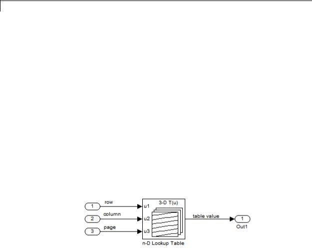
Supported Block Operations |
|
The n-D Lookup Table block evaluates a sampled representation of |
|
a function in N variables |
|
y = F(x1, x2 , x3 ,..., xN ) |
|
where the function F can be empirical. The block maps inputs to an |
|
output value by looking up or interpolating a table of values you define |
|
with block parameters. The block supports flat (constant), linear, and |
|
cubic-spline interpolation methods. You can apply these methods to a |
|
table of any dimension from 1 through 30. |
|
In the following block, the first input identifies the first dimension (row) |
|
breakpoints, the second input identifies the second dimension (column) |
|
breakpoints, and so on. |
See “How to Rotate a Block” in the Simulink documentation for a description of the port order for various block orientations.
Specification of Breakpoint and Table Data
The following block parameters define the breakpoint and table data.
2-886

n-D Lookup Table
|
Block Parameter |
Purpose |
|
|
Number of table dimensions |
Specifies the number of |
|
|
|
dimensions of your lookup |
|
|
|
table. |
|
|
Breakpoints |
Specifies a breakpoint vector that |
|
|
|
corresponds to each dimension of |
|
|
|
your lookup table. |
|
|
Table data |
Defines the associated set of |
|
|
|
output values. |
|
Tip Evenly spaced breakpoints can make the generated code division-free. For more information, see fixpt_evenspace_cleanup in the Simulink documentation and “Identify questionable fixed-point operations” in the Simulink Coder documentation.
How the Block Generates Output
The n-D Lookup Table block generates output by looking up or estimating table values based on the input values:
|
When block inputs... |
The n-D Lookup Table block... |
|
|
Match the values of indices in |
Outputs the table value at |
|
|
breakpoint data sets |
the intersection of the row, |
|
|
|
column, and higher dimension |
|
|
|
breakpoints |
|
|
Do not match the values of indices |
Interpolates appropriate table |
|
|
in breakpoint data sets, but are |
values, using the Interpolation |
|
|
within range |
method you select |
|
|
Do not match the values of indices |
Extrapolates the output value, |
|
|
in breakpoint data sets, and are |
using the Extrapolation |
|
|
out of range |
method you select |
|
2-887

n-D Lookup Table
Data Type
Support
Other Blocks That Perform Equivalent Operations
You can use the Interpolation Using Prelookup block with the Prelookup block to perform the equivalent operation of one n-D Lookup Table block. This combination of blocks offers greater flexibility that can result in more efficient simulation performance for linear interpolations.
When the lookup operation is an array access that does not require interpolation, use the Direct Lookup Table (n-D) block. For example, if you have an integer value k and you want the kth element of a table, y = table(k), interpolation is unnecessary.
The n-D Lookup Table block supports all numeric data types that Simulink supports, including fixed-point data types. For more information, see “Data Types Supported by Simulink” in the Simulink documentation.
For cubic spline interpolation and linear extrapolation modes, the following parameters must use the same floating-point type:
•Table data
•Breakpoints
•Fraction
•Intermediate results
•Output
Inputs for indexing must be real, but table data can be complex.
2-888
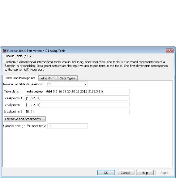
n-D Lookup Table
Parameters The Table and Breakpoints pane of the n-D Lookup Table block and dialog box appears as follows:
Dialog Box
Number of table dimensions
Enter the number of dimensions of the lookup table by specifying an integer from 1 to 30. This parameter determines:
2-889

n-D Lookup Table
•The number of independent variables for the table and the number of block inputs
•The number of breakpoint sets to specify
Table data
Enter the table of output values.
During simulation, the matrix size must match the dimensions defined by the Number of table dimensions parameter. However, during block diagram editing, you can enter an empty matrix (specified as []) or an undefined workspace variable. This technique lets you postpone specifying a correctly dimensioned matrix for the table data and continue editing the block diagram. For information about how to construct multidimensional arrays in MATLAB, see “Multidimensional Arrays” in the MATLAB online documentation.
Breakpoints
In each Breakpoints row, enter the breakpoint set that corresponds to each dimension of table data. For each dimension, specify breakpoints as a 1-by-n or n-by-1 vector whose values are strictly monotonically increasing.
Edit table and breakpoints
Click this button to open the Lookup Table Editor. For more information, see “Edit Existing LookupTables” in the Simulink documentation.
Sample time (-1 for inherited)
Specify the time interval between samples. To inherit the sample time, set this parameter to -1. See “Specify Sample Time” in the Simulink documentation.
2-890
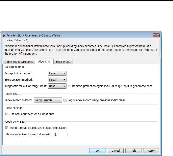
n-D Lookup Table
The Algorithm pane of the n-D Lookup Table block dialog box appears as follows:
Interpolation method
Select Flat, Linear, or Cubic spline. See “Interpolation Methods” in the Simulink documentation for more information.
If you select Cubic spline, the block supports only scalar signals. The other interpolation methods support nonscalar signals.
2-891

n-D Lookup Table
Extrapolation method
Select Clip, Linear, or Cubic spline. See “Extrapolation Methods” in the Simulink documentation for more information.
To select Cubic spline for Extrapolation method, you must also select Cubic spline for Interpolation method.
Use last table value for inputs at or above last breakpoint
Specify the indexing convention that the block uses to address the last element of a breakpoint set and its corresponding table value.
|
Check Box |
Index That the |
Interval Fraction |
|
|
|
Block Uses |
|
|
|
Selected |
Last element of a |
0 |
|
|
|
breakpoint set |
|
|
|
Cleared |
Next-to-last |
1 |
|
|
|
element of a |
|
|
|
|
breakpoint set |
|
|
This parameter is visible only when:
•Interpolation method is Linear.
•Extrapolation method is Clip.
Diagnostic for out-of-range input
Specify whether to produce a warning or error when the input is out of range. Options include:
•None — no warning or error
•Warning — display a warning in the MATLAB Command Window and continue the simulation
•Error — halt the simulation and display an error in the Simulation Diagnostics Viewer
2-892
n-D Lookup Table
Remove protection against out-of-range input in generated code
Specify whether or not to include code that checks for out-of-range breakpoint input values.
|
Check Box |
Result |
When to Use |
|
|
Selected |
Generated code |
For code efficiency |
|
|
|
does not include |
|
|
|
|
conditional |
|
|
|
|
statements to check |
|
|
|
|
for out-of-range |
|
|
|
|
breakpoint inputs. |
|
|
|
Cleared |
Generated code |
For safety-critical |
|
|
|
includes conditional |
applications |
|
|
|
statements to check |
|
|
|
|
for out-of-range |
|
|
|
|
breakpoint inputs. |
|
|
Depending on your application, you can run the following Model Advisor checks to verify the usage of this check box:
•By Product > Embedded Coder > Identify lookup table blocks that generate expensive out-of-range checking code
•By Product > Simulink Verification and Validation > Modeling Standards > DO-178C/DO-331 Checks > Check usage of lookup table blocks
For more information about the Model Advisor, see “Consult the Model Advisor” in the Simulink documentation.
Index search method
Select Evenly spaced points, Linear search, or Binary search. Each search method has speed advantages in different circumstances:
2-893

n-D Lookup Table
•For evenly spaced breakpoint sets (for example, 10, 20, 30, and so on), you achieve optimal speed by selecting Evenly spaced points to calculate table indices.
This algorithm uses only the first two breakpoints of a set to determine the offset and spacing of the remaining points.
•For unevenly spaced breakpoint sets, follow these guidelines:
—If input signals do not vary much between time steps, selecting Linear search with Begin index search using previous index result produces the best performance.
—If input signals jump more than one or two table intervals per time step, selecting Binary search produces the best performance.
A suboptimal choice of index search method can lead to slow performance of models that rely heavily on lookup tables.
Note The generated code stores only the first breakpoint, the spacing, and the number of breakpoints when:
•The breakpoint data is not tunable.
•The index search method is Evenly spaced points.
Begin index search using previous index result
Select this check box when you want the block to start its search using the index found at the previous time step. For inputs that change slowly with respect to the interval size, enabling this option can improve performance. Otherwise, the linear search and binary search methods can take longer, especially for large breakpoint sets.
Use one input port for all input data
Select this check box to use only one input port that expects a signal that is N elements wide for an N-dimensional table. This
2-894

n-D Lookup Table
option is useful for removing line clutter on a block diagram with many lookup tables.
Note When you select this check box, one input port with the label u appears on the block.
Support tunable table size in code generation
Select this check box to enable tunable table size in the generated code. This option enables you to change the size and values of the lookup table and breakpoint data without regenerating or recompiling the code.
If you set Interpolation method to Cubic spline, this check box is not available.
Maximum indices for each dimension
Specify the maximum index values for each table dimension using zero-based indexing. You can specify a scalar or vector of positive integer values using the following data types:
•Built-in floating-point types: double and single
•Built-in integer types: int8, int16, int32, uint8, uint16, and uint32
Here are some examples of valid specifications:
•[4 6] for a 5-by-7 table
•[int8(2) int16(5) int32(9)] for a 3-by-6-by-10 table
This parameter is available when you select Support tunable table size in code generation.
2-895
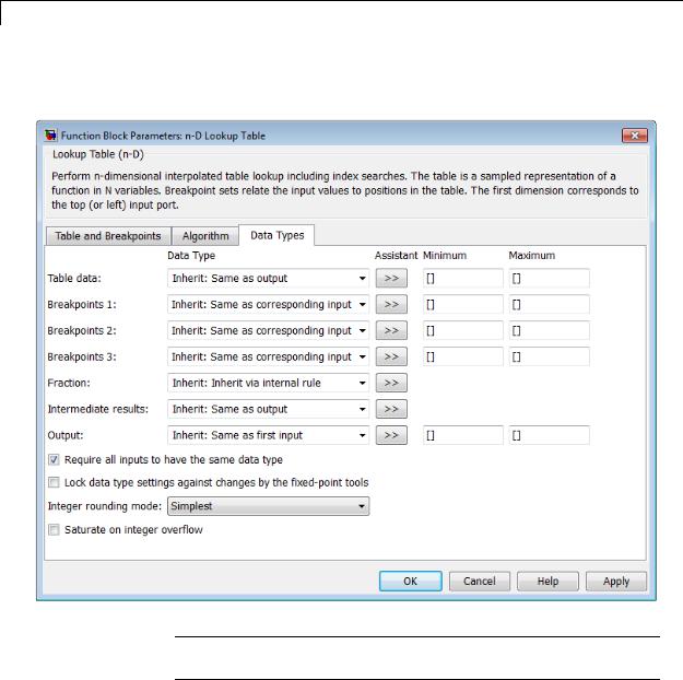
n-D Lookup Table
The Data Types pane of the n-D Lookup Table block dialog box appears as follows:
Note The dialog box can expand to show additional data type options. Up to 30 breakpoint data type specifications can appear.
2-896

n-D Lookup Table
Table data > Data Type
Specify the table data type. You can set it to:
•A rule that inherits a data type, for example, Inherit: Same as output
•The name of a built-in data type, for example, single
•The name of a data type object, for example, a
Simulink.NumericType object
•An expression that evaluates to a data type, for example, fixdt(1,16,0)
Click the Show data type assistant button  to display the Data Type Assistant, which helps you set the table data type.
Tip Specify a table data type different from the output data type for these cases:
•Lower memory requirement for storing table data that uses a smaller type than the output signal
•Sharing of prescaled table data between two n-D Lookup Table blocks with different output data types
•Sharing of custom storage table data in the generated code for blocks with different output data types
Table data > Minimum
Specify the minimum value for table data. The default value is [] (unspecified).
Table data > Maximum
Specify the maximum value for table data. The default value is [] (unspecified).
2-897

n-D Lookup Table
Breakpoints > Data Type
Specify the data type for a set of breakpoint data. You can set it to:
•A rule that inherits a data type, for example, Inherit: Same as corresponding input
•The name of a built-in data type, for example, single
•The name of a data type object, for example, a
Simulink.NumericType object
•An expression that evaluates to a data type, for example, fixdt(1,16,0)
Click the Show data type assistant button  to display the Data Type Assistant, which helps you set the breakpoint data type.
See “Specify Data Types Using Data Type Assistant” in the Simulink documentation for more information.
Tip Specify a breakpoint data type different from the corresponding input data type for these cases:
•Lower memory requirement for storing breakpoint data that uses a smaller type than the input signal
•Sharing of prescaled breakpoint data between two n-D Lookup Table blocks with different input data types
•Sharing of custom storage breakpoint data in the generated code for blocks with different input data types
Breakpoints > Minimum
Specify the minimum value that a set of breakpoint data can have. The default value is [] (unspecified).
2-898

n-D Lookup Table
Breakpoints > Maximum
Specify the maximum value that a set of breakpoint data can have. The default value is [] (unspecified).
Fraction > Data Type
Specify the fraction data type. You can set it to:
•A rule that inherits a data type, for example, Inherit: Inherit via internal rule
•The name of a built-in data type, for example, single
•The name of a data type object, for example, a
Simulink.NumericType object
•An expression that evaluates to a data type, for example, fixdt(1,16,0)
Click the Show data type assistant button  to display the Data Type Assistant, which helps you set the fraction data type.
See “Specify Data Types Using Data Type Assistant” in the Simulink documentation for more information.
Intermediate results > Data Type
Specify the intermediate results data type. You can set it to:
•A rule that inherits a data type, for example, Inherit: Same as output
•The name of a built-in data type, for example, single
•The name of a data type object, for example, a
Simulink.NumericType object
•An expression that evaluates to a data type, for example, fixdt(1,16,0)
2-899

n-D Lookup Table
Click the Show data type assistant button  to display the Data Type Assistant, which helps you set the intermediate results data type.
Tip Use this parameter to specify higher (or lower) precision for internal computations than for table data or output data.
Output > Data Type
Specify the output data type. You can set it to:
•A rule that inherits a data type, for example, Inherit: Inherit via back propagation
•The name of a built-in data type, for example, single
•The name of a data type object, for example, a
Simulink.NumericType object
•An expression that evaluates to a data type, for example, fixdt(1,16,0)
Click the Show data type assistant button  to display the Data Type Assistant, which helps you set the output data type.
See “Specify Block Output Data Types” for more information.
Output > Minimum
Specify the minimum value that the block outputs. The default value is [] (unspecified). Simulink software uses this value to perform:
•Parameter range checking (see “Check Parameter Values”)
•Simulation range checking (see “Signal Ranges”)
•Automatic scaling of fixed-point data types
2-900

n-D Lookup Table
Output > Maximum
Specify the maximum value that the block outputs. The default value is [] (unspecified). Simulink software uses this value to perform:
•Parameter range checking (see “Check Parameter Values”)
•Simulation range checking (see “Signal Ranges”)
•Automatic scaling of fixed-point data types
Require all inputs to have the same data type
Select to require all inputs to have the same data type.
Lock data type settings against changes by the fixed-point tools
Select to lock all data type settings of this block against changes by the Fixed-Point Tool and the Fixed-Point Advisor. For more information, see “Overview of the Fixed-Point Tool” and “Preparation for Fixed-Point Conversion” in the Simulink Fixed Point documentation.
Integer rounding mode
Specify the rounding mode for fixed-point lookup table calculations that occur during simulation or execution of code generated from the model. For more information, see “Rounding” in the Simulink® Fixed Point™ documentation.
This option does not affect rounding of values of block parameters. Simulink rounds such values to the nearest representable integer value. To control the rounding of a block parameter, enter an expression using a MATLAB rounding function into the edit field on the block dialog box.
2-901

n-D Lookup Table
Saturate on integer overflow
|
Action |
Reasons for Taking |
What Happens for |
Example |
|
|
|
This Action |
Overflows |
|
|
|
Select this |
Your model has |
Overflows saturate to |
An overflow associated |
|
|
check box. |
possible overflow and |
either the minimum |
with a signed 8-bit |
|
|
|
you want explicit |
or maximum value |
integer can saturate to |
|
|
|
saturation protection |
that the data type can |
-128 or 127. |
|
|
|
in the generated code. |
represent. |
|
|
|
Do not select |
You want to optimize |
Overflows wrap to the |
The number 130 does |
|
|
this check |
efficiency of your |
appropriate value that |
not fit in a signed 8-bit |
|
|
box. |
generated code. |
is representable by the |
integer and wraps to |
|
|
|
You want to avoid |
data type. |
-126. |
|
|
|
|
|
||
|
|
overspecifying how |
|
|
|
|
|
a block handles |
|
|
|
|
|
out-of-range signals. |
|
|
|
|
|
For more information, |
|
|
|
|
|
see “Checking for |
|
|
|
|
|
Signal Range Errors”. |
|
|
|
|
|
|
|
||
|
|
|
Tip If you save your model as version R2009a or earlier, this |
||
|
|
|
check box setting has no effect and no saturation code appears. |
||
|
|
|
This behavior preserves backward compatibility. |
||
|
|
|
|
||
|
|
|
When you select this check box, saturation applies to every |
||
|
|
|
internal operation on the block, not just the output or result. In |
||
|
|
|
general, the code generation process can detect when overflow is |
||
|
|
|
not possible. In this case, the code generator does not produce |
||
|
|
|
saturation code. |
|
|
2-902
n-D Lookup Table
Examples Interpolation and Extrapolation Behavior
For an example that illustrates linear interpolation and extrapolation methods of this block, see “Create a Logarithm Lookup Table” in the Simulink documentation.
For an example of entering breakpoint and table data, see “Entering Data in a Block Parameter Dialog Box” in the Simulink documentation.
Tunable Table Size in the Generated Code
Suppose that you have a lookup table and want to make the size tunable in the generated code. Assume that:
•You define a Simulink.Parameter structure in the preload function of your model:
p = Simulink.Parameter; p.Value.MaxIdx = [2 2]; p.Value.BP1 = [1 2 3]; p.Value.BP2 = [1 4 16];
p.Value.Table = [4 5 6; 16 19 20; 10 18 23]; p.DataType = 'Bus: slLookupTable'; p.CoderInfo.StorageClass = 'ExportedGlobal';
% Create bus object slBus1 from MATLAB structure Simulink.Bus.createObject(p.Value); slLookupTable = slBus1; slLookupTable.Elements(1).DataType = 'uint32';
•The following block parameters apply in the n-D Lookup Table block dialog box:
|
Parameter |
Value |
|
|
Number of table dimensions |
2 |
|
|
Table data |
p.Table |
|
|
Breakpoints 1 |
p.BP1 |
|
|
|
|
|
2-903

n-D Lookup Table
|
Parameter |
Value |
|
|
Breakpoints 2 |
p.BP2 |
|
|
Support tunable table size in |
on |
|
|
code generation |
|
|
|
Maximum indices for each |
p.MaxIdx |
|
|
dimension |
|
|
The generated model_types.h header file contains a type definition that looks something like this:
typedef struct { uint32_T MaxIdx[2]; real_T BP1[3]; real_T BP2[3]; real_T Table[9];
} slLookupTable;
The generated model.c file contains code that looks something like this:
/* Exported block parameters */ slLookupTable p = {
{2U, 2U },
{1.0, 2.0, 3.0 },
{1.0, 4.0, 16.0 },
{4.0, 16.0, 10.0, 5.0, 19.0, 18.0, 6.0, 20.0, 23.0 }
};
/* More code */
/* Model output function */
static void ex_lut_nd_tunable_table_output(int_T tid)
{
2-904

n-D Lookup Table
/* Lookup_n-D: '<Root>/n-D Lookup Table' incorporates:
*Inport: '<Root>/In1'
*Inport: '<Root>/In2'
*/
Y = look2_binlcpw(U1, U2, p.BP1, p.BP2, p.Table, ...
p.MaxIdx, p.MaxIdx[0] + 1U);
/* Outport: '<Root>/Out1' */ ex_lut_nd_tunable_table_Y.Out1 = Y;
/* tid is required for a uniform function interface. * Argument tid is not used in the function. */
UNUSED_PARAMETER(tid);
}
The highlighted line of code specifies a tunable table size for the lookup table. You can change the size and values of the lookup table and breakpoint data without regenerating or recompiling the code.
Characteristics |
|
Direct Feedthrough |
Yes |
|
|
Sample Time |
Specified in the Sample time |
|
|
|
parameter |
|
|
Scalar Expansion |
Yes |
|
|
Dimensionalized |
Yes, if you do not select Cubic |
|
|
|
spline for Interpolation method |
|
|
Zero-Crossing Detection |
No |
See Also |
|
Prelookup, Interpolation Using Prelookup |
|
2-905

Lookup Table Dynamic
Purpose |
Approximate one-dimensional function using dynamic table |
Library |
Lookup Tables |
Description |
How This Block Differs from Other Lookup Table Blocks |
|
The Lookup Table Dynamic block computes an approximation of a |
|
function y = f(x) using xdat and ydat vectors. The lookup method can |
|
use interpolation, extrapolation, or the original values of the input. |
|
Using the Lookup Table Dynamic block, you can change the table data |
|
without stopping the simulation. For example, you can incorporate new |
|
table data if the physical system you are simulating changes. |
|
Inputs for Breakpoint and Table Data |
|
The xdat vector is the breakpoint data, which must be strictly |
|
monotonically increasing. The value of the next element in the |
|
vector must be greater than the value of the preceding element after |
|
conversion to a fixed-point data type. Due to quantization, xdat can be |
|
strictly monotonic for a floating-point data type, but not after conversion |
|
to a fixed-point data type. |
|
The ydat vector is the table data, which is an evaluation of the function |
|
at the breakpoint values. |
|
|
|
Note The inputs to xdat and ydat cannot be scalar (one-element |
|
array) values. If you provide a scalar value to either of these inputs, |
|
you see an error upon simulation. Provide a 1-by-n vector to both the |
|
xdat and ydat inputs. |
|
|
|
Lookup Table Definition |
|
You define the lookup table by feeding xdat and ydat as 1-by-n vectors |
|
to the block. To reduce ROM usage in the generated code for this block, |
|
you can use different data types for xdat and ydat. However, these |
|
restrictions apply: |
2-906

Lookup Table Dynamic
•The xdat breakpoint data and the x input vector must have the same sign, bias, and fractional slope. Also, the precision and range for x must be greater than or equal to the precision and range for xdat.
•The ydat table data and the y output vector must have the same sign, bias, and fractional slope.
Tip Breakpoints with even spacing can make Simulink Coder generated code division-free. For more information, see fixpt_evenspace_cleanup in the Simulink documentation and “Identify questionable fixed-point operations” in the Simulink Coder documentation.
How the Block Generates Output
The block uses the input values to generate output using the method you select for Lookup Method:
|
Lookup Method |
Block Action |
|
|
Interpolation-Extrapolation |
Performs linear interpolation and extrapolation of |
|
|
|
the inputs. |
|
|
|
• If the input matches a breakpoint, the output is |
|
|
|
the corresponding element in the table data. |
|
|
|
• If the input does not match a breakpoint, the |
|
|
|
block performs linear interpolation between two |
|
|
|
elements of the table to determine the output. If |
|
|
|
the input falls outside the range of breakpoint |
|
|
|
values, the block extrapolates using the first two |
|
|
|
or last two points. |
|
|
|
|
|
2-907

Lookup Table Dynamic
Lookup Method |
|
Block Action |
|
|
|
|
|
|
|
|
|
|
|
Note If you select this lookup method, Simulink |
|
|
|
Coder software cannot generate code for this block. |
|
|
|
|
|
Interpolation-Use End Values |
|
Performs linear interpolation but does not |
|
(default) |
|
extrapolate outside the end points of the breakpoint |
|
|
|
data. Instead, the block uses the end values. |
|
Use Input Nearest |
|
Finds the element in xdat nearest the current |
|
|
|
input. The corresponding element in ydat is the |
|
|
|
output. |
|
Use Input Below |
|
Finds the element in xdat nearest and below the |
|
|
|
current input. The corresponding element in ydat |
|
|
|
is the output. If there is no element in xdat below |
|
|
|
the current input, the block finds the nearest |
|
|
|
element. |
|
Use Input Above |
|
Finds the element in xdat nearest and above the |
|
|
|
current input. The corresponding element in ydat |
|
|
|
is the output. If there is no element in xdat above |
|
|
|
the current input, the block finds the nearest |
|
|
|
element. |
|
Note The Use Input Nearest, Use Input Below, and Use Input Above methods perform the same action when the input x matches a breakpoint value.
Some continuous solvers subdivide the simulation time span into major and minor time steps. A minor time step is a subdivision of the major time step. The solver produces a result at each major time step and uses results at minor time steps to improve the accuracy of the result at the major time step. For continuous solvers, the output of the Lookup Table
2-908

Lookup Table Dynamic
Data Type
Support
Dynamic block can appear like a stair step because the signal is fixed in minor time step to avoid incorrect results. For more information about the effect of solvers on block output, see “Solvers” in the Simulink documentation.
The Lookup Table Dynamic block accepts signals of the following data types:
•Floating point
•Built-in integer
•Fixed point
•Boolean
For more information, see “Data Types Supported by Simulink” in the Simulink documentation.
2-909
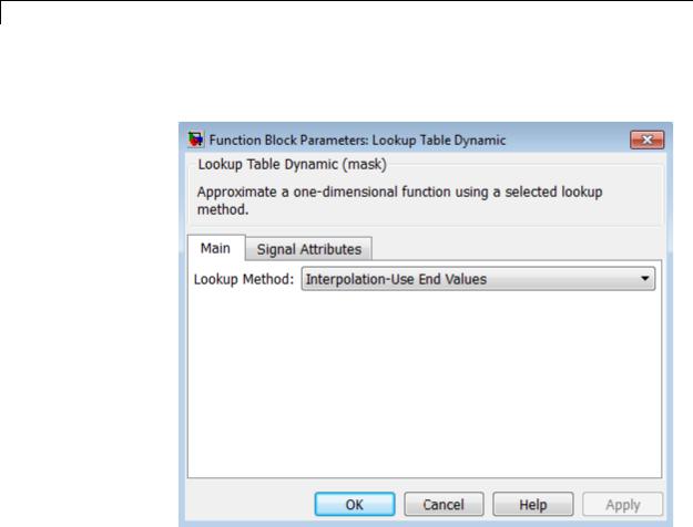
Lookup Table Dynamic
Parameters |
The Main pane of the Lookup Table Dynamic block dialog box appears |
and |
as follows: |
Dialog |
|
Box |
|
Lookup Method
Specify the lookup method. For details, see “How the Block
Generates Output” on page 2-907.
2-910

Lookup Table Dynamic
The Signal Attributes pane of the Lookup Table Dynamic block dialog box appears as follows:
Output data type
Specify the output data type. You can set it to:
•A rule that inherits a data type, for example, Inherit: Inherit via back propagation
•The name of a built-in data type, for example, single
•The name of a data type object, for example, a
Simulink.NumericType object
2-911

Lookup Table Dynamic
Examples
•An expression that evaluates to a data type, for example, fixdt('double')
Click the Show data type assistant button  to display the Data Type Assistant, which helps you set the
Output data type parameter.
See “Specify Block Output Data Types” for more information.
Lock output data type setting against changes by the fixed-point tools
Select to lock the output data type setting of this block against changes by the Fixed-Point Tool and the Fixed-Point Advisor. For more information, see “Use Lock Output Data Type Setting”.
Integer rounding mode
Specify the rounding mode for fixed-point operations. For more information, see “Rounding”. in the Simulink Fixed Point documentation.
Saturate to max or min when overflows occur
Select to have overflows saturate to the maximum or minimum value that the data type can represent. Otherwise, overflows wrap.
When you select this check box, saturation applies to every internal operation on the block, not just the output or result. In general, the code generation process can detect when overflow is not possible. In this case, the code generator does not produce saturation code.
|
For an example of... |
See... |
|
|
Breakpoint and table data entry |
“Entering Data Using Inports of |
|
|
|
the Lookup Table Dynamic Block” |
|
|
Block output for different lookup |
“Example Output for Lookup |
|
|
methods |
Methods” |
|
2-912
Lookup Table Dynamic
Characteristics
See Also
Direct Feedthrough |
Yes |
Scalar Expansion |
No |
Zero-Crossing Detection |
No |
|
|
n-D Lookup Table
2-913

Magnitude-Angle to Complex
Purpose |
Convert magnitude and/or a phase angle signal to complex signal |
Library |
Math Operations |
Description |
Supported Operations |
|
The Magnitude-Angle to Complex block converts magnitude and phase |
|
angle inputs to a complex output. The angle input must be in radians. |
|
The block supports the following combinations of input dimensions |
|
when there are two block inputs: |
|
• Two inputs of equal dimensions |
|
• One scalar input and the other an n-dimensional array |
|
If the block input is an array, the output is an array of complex signals. |
|
The elements of a magnitude input vector map to the magnitudes of the |
|
corresponding complex output elements. Similarly, the elements of |
|
an angle input vector map to the angles of the corresponding complex |
|
output elements. If one input is a scalar, it maps to the corresponding |
|
component (magnitude or angle) of all the complex output signals. |
|
Effect of Out-of-Range Input on CORDIC Approximations |
|
If you use the CORDIC approximation method (see “Definitions” on page |
|
2-915), the block input for phase angle has the following restrictions: |
|
• For signed fixed-point types, the input angle must fall within the |
|
range [–2π, 2π) radians. |
|
• For unsigned fixed-point types, the input angle must fall within the |
|
range [0, 2π) radians. |
2-914

Magnitude-Angle to Complex
The following table summarizes what happens for an out-of-range input:
|
Block Usage |
Effect of Out-of-Range Input |
|
|
Simulation |
An error appears. |
|
|
Generated code |
Undefined behavior occurs. |
|
|
Accelerator modes |
|
|
|
|
|
|
Ensure that you use an in-range input for the Magnitude-Angle to Complex block when you use the CORDIC approximation. Avoid relying on undefined behavior for generated code or Accelerator modes.
Definitions CORDIC
Data Type
Support
CORDIC is an acronym for COordinate Rotation DIgital Computer. The Givens rotation-based CORDIC algorithm is among one of the most hardware-efficient algorithms available because it requires only iterative shift-add operations (see [1], [2]) The CORDIC algorithm eliminates the need for explicit multipliers. Using CORDIC, you can calculate various functions, such as sine, cosine, arc sine, arc cosine, arc tangent, and vector magnitude. You can also use this algorithm for divide, square root, and hyperbolic, and logarithmic functions.
Increasing the number of CORDIC iterations can produce more accurate results, but doing so also increases the expense of the computation and adds latency.
The block accepts real input signals of the following data types:
•Floating point
•Fixed point (only when Approximation method is CORDIC)
The following restrictions also apply:
•If one input uses a floating-point type, the other input must use the same data type. For example, both signals must be double or single.
2-915

Magnitude-Angle to Complex
Parameters and Dialog Box
•If one input uses a fixed-point type, the other input must also use a fixed-point type.
The dialog box for this block appears as follows:
Input
Specify the kind of input: a magnitude input, an angle input, or both.
2-916

Magnitude-Angle to Complex
Angle (Magnitude)
|
Input |
What to Specify |
|
|
Magnitude |
The constant phase angle of |
|
|
|
the output signal in radians |
|
|
Angle |
The constant magnitude of the |
|
|
|
output signal |
|
This parameter is not available when Input is Magnitude and angle.
Approximation method
Specify the type of approximation for computing output.
|
Approximation |
Data Types |
When to Use This |
|
|
Method |
Supported |
Method |
|
|
None (default) |
Floating point |
You want to use |
|
|
|
|
the default Taylor |
|
|
|
|
series algorithm. |
|
|
CORDIC |
Floating point and |
You want a fast, |
|
|
|
fixed point |
approximate |
|
|
|
|
calculation. |
|
When you use the CORDIC approximation, follow these guidelines:
•For signed fixed-point types, the input angle must fall within the range [–2π, 2π) radians.
•For unsigned fixed-point types, the input angle must fall within the range [0, 2π) radians.
2-917

Magnitude-Angle to Complex
The block uses the following data type propagation rules:
|
Data Type of |
Approximation |
Data Type of Complex |
|
|
Magnitude |
Method |
Output |
|
|
Input |
|
|
|
|
Floating point |
None or CORDIC |
Same as input |
|
|
Signed, fixed |
CORDIC |
fixdt(1, WL + 2, FL) |
|
|
point |
|
where WL and FL are the |
|
|
|
|
|
|
|
|
|
word length and fraction |
|
|
|
|
length of the magnitude |
|
|
Unsigned, |
CORDIC |
fixdt(1, WL + 3, FL) |
|
|
fixed point |
|
where WL and FL are the |
|
|
|
|
|
|
|
|
|
word length and fraction |
|
|
|
|
length of the magnitude |
|
Number of iterations
Specify the number of iterations to perform the CORDIC algorithm. The default value is 11.
|
Data Type of Block Inputs |
Value You Can Specify |
|
|
Floating point |
A positive integer |
|
|
Fixed point |
A positive integer that does |
|
|
|
not exceed the word length |
|
|
|
of the magnitude input or |
|
|
|
the word length of the phase |
|
|
|
angle input, whichever value |
|
|
|
is smaller |
|
Entering a value that is not a positive integer causes an error.
This parameter is available when you set Approximation method to CORDIC.
2-918

Magnitude-Angle to Complex
Scale output by reciprocal of gain factor
Select this check box to scale the real and imaginary parts of the complex output by a factor of (1/CORDIC gain). This value depends on the number of iterations you specify. As the number of iterations goes up, the value approaches 1.647.
This check box is selected by default, which leads to a more numerically accurate result for the complex output, X + iY. However, scaling the output adds two extra multiplication operations, one for X and one for Y.
This parameter is available when you set Approximation method to CORDIC.
Sample time (-1 for inherited)
Specify the time interval between samples. To inherit the sample time, set this parameter to -1. See “Specify Sample Time” in the online documentation for more information.
Characteristics |
|
Direct Feedthrough |
Yes |
|
|
Sample Time |
Specified by the Sample time |
|
|
|
parameter |
|
|
Scalar Expansion |
Yes, of the input when the function |
|
|
|
requires two inputs |
|
|
Dimensionalized |
Yes |
|
|
Multidimensionalized |
Yes |
|
|
Zero-Crossing Detection |
No |
References |
|
[1] Volder, J.E. “The CORDIC Trigonometric Computing Technique,” |
|
|
|
IRE Transactions on Electronic Computers. Vol. EC-8, September |
|
|
|
1959, pp. 330–334. |
|
[2] Andraka, R. “A survey of CORDIC algorithm for FPGA based computers.” Proceedings of the 1998 ACM/SIGDA sixth international
2-919

Magnitude-Angle to Complex
|
symposium on Field programmable gate arrays. Feb. 22–24, 1998, pp. |
|
191–200. |
See Also |
Complex to Magnitude-Angle |
2-920

Manual Switch
Purpose |
Switch between two inputs |
Library |
Signal Routing |
Description |
The Manual Switch block is a toggle switch that selects one of its |
|
two inputs to pass through to the output. To toggle between inputs, |
|
double-click the block. The block propagates the selected input to |
|
the output, while the block discards the unselected input. You can |
|
interactively control the signal flow by setting the switch before you |
|
start the simulation or by changing the switch while the simulation is |
|
executing. The Manual Switch block retains its current state when |
|
you save the model. |
Data Type
Support
The Manual Switch block accepts real or complex signals of any data type that Simulink supports, including fixed-point and enumerated data types. For more information, see “Data Types Supported by Simulink” in the Simulink documentation.
Parameters Double-clicking the Manual Switch block toggles the input. To open the and block dialog box, right-click the block and select Block Parameters.
Dialog Box
• “Allow the two inputs to differ in size” on page 2-923
2-921

Manual Switch
• “Sample time (-1 for inherited)” on page 2-1938
2-922