

- •Block Reference
- •Commonly Used
- •Continuous
- •Discontinuities
- •Discrete
- •Logic and Bit Operations
- •Lookup Tables
- •Math Operations
- •Model Verification
- •Model-Wide Utilities
- •Ports & Subsystems
- •Signal Attributes
- •Signal Routing
- •Sinks
- •Sources
- •User-Defined Functions
- •Additional Math & Discrete
- •Additional Discrete
- •Additional Math: Increment — Decrement
- •Run on Target Hardware
- •Target for Use with Arduino Hardware
- •Target for Use with BeagleBoard Hardware
- •Target for Use with LEGO MINDSTORMS NXT Hardware
- •Blocks — Alphabetical List
- •Command-Line Information
- •Command-Line Information
- •Command-Line Information
- •Command-Line Information
- •Command-Line Information
- •Command-Line Information
- •Command-Line Information
- •Command-Line Information
- •Command-Line Information
- •Command-Line Information
- •Command-Line Information
- •Command-Line Information
- •Command-Line Information
- •Command-Line Information
- •Command-Line Information
- •Command-Line Information
- •Settings Pane
- •Measurements Pane
- •Signal Statistics Measurements
- •Settings Pane
- •Transitions Pane
- •Overshoots/Undershoots
- •Cycles
- •Settings Pane
- •Peaks Pane
- •Command-Line Information
- •Command-Line Information
- •Command-Line Information
- •Command-Line Information
- •Command-Line Information
- •Command-Line Information
- •Command-Line Information
- •Command-Line Information
- •Command-Line Information
- •Function Reference
- •Model Construction
- •Simulation
- •Linearization and Trimming
- •Data Type
- •Examples
- •Main Toolbar
- •Command-Line Alternative
- •Command-Line Alternative
- •Command-Line Alternative
- •Command-Line Alternative
- •Command-Line Alternative
- •Command-Line Alternative
- •Mask Icon Drawing Commands
- •Simulink Classes
- •Model Parameters
- •About Model Parameters
- •Examples of Setting Model Parameters
- •Common Block Parameters
- •About Common Block Parameters
- •Examples of Setting Block Parameters
- •Block-Specific Parameters
- •Mask Parameters
- •About Mask Parameters
- •Notes on Mask Parameter Storage
- •Simulink Identifier
- •Simulink Identifier
- •Model Advisor Checks
- •Simulink Checks
- •Simulink Check Overview
- •See Also
- •Identify unconnected lines, input ports, and output ports
- •Description
- •Results and Recommended Actions
- •Capabilities and Limitations
- •Tips
- •See Also
- •Check root model Inport block specifications
- •Description
- •Results and Recommended Actions
- •See Also
- •Check optimization settings
- •Description
- •Results and Recommended Actions
- •Tips
- •See Also
- •Description
- •Results and Recommended Actions
- •See Also
- •Check for implicit signal resolution
- •Description
- •Results and Recommended Actions
- •See Also
- •Check for optimal bus virtuality
- •Description
- •Results and Recommended Actions
- •Capabilities and Limitations
- •See Also
- •Description
- •Results and Recommended Actions
- •Capabilities and Limitations
- •See Also
- •Identify disabled library links
- •Description
- •Results and Recommended Actions
- •Capabilities and Limitations
- •Tips
- •See Also
- •Identify parameterized library links
- •Description
- •Results and Recommended Actions
- •Capabilities and Limitations
- •Tips
- •See Also
- •Identify unresolved library links
- •Description
- •Results and Recommended Actions
- •Capabilities and Limitations
- •See Also
- •Results and Recommended Actions
- •Capabilities and Limitations
- •See Also
- •Results and Recommended Actions
- •Capabilities and Limitations
- •See Also
- •Check usage of function-call connections
- •Description
- •Results and Recommended Actions
- •See Also
- •Check signal logging save format
- •Description
- •Results and Recommended Actions
- •See Also
- •Description
- •Results and Recommended Actions
- •See Also
- •Description
- •Results and Recommended Actions
- •Tips
- •See Also
- •Check data store block sample times for modeling errors
- •Description
- •Results and Recommended Actions
- •See Also
- •Check for potential ordering issues involving data store access
- •Description
- •Results and Recommended Actions
- •Tips
- •See Also
- •Check for partial structure parameter usage with bus signals
- •Description
- •Results and Recommended Actions
- •Tips
- •See Also
- •Check for calls to slDataTypeAndScale
- •Description
- •Results and Recommended Actions
- •Tips
- •See Also
- •Check for proper bus usage
- •Description
- •Results and Recommended Actions
- •Action Results
- •Tips
- •See Also
- •Description
- •Results and Recommended Actions
- •See Also
- •Description
- •Results and Recommended Actions
- •See Also
- •Check for proper Merge block usage
- •Description
- •Input Parameters
- •Results and Recommended Actions
- •See Also
- •Description
- •Results and Recommended Actions
- •Action Results
- •See Also
- •Check for non-continuous signals driving derivative ports
- •Description
- •Results and Recommended Actions
- •See Also
- •Runtime diagnostics for S-functions
- •Description
- •Results and Recommended Actions
- •See Also
- •Check file for foreign characters
- •Description
- •Results and Recommended Actions
- •Tips
- •See Also
- •Check model for known block upgrade issues
- •Description
- •Results and Recommended Actions
- •Action Results
- •See Also
- •Description
- •Results and Recommended Actions
- •Action Results
- •See Also
- •Check that the model is saved in SLX format
- •Description
- •Results and Recommended Actions
- •Tips
- •See Also
- •Check Model History properties
- •Description
- •Results and Recommended Actions
- •See Also
- •Analyze model hierarchy for upgrade issues
- •Description
- •Results and Recommended Actions
- •Tips
- •See Also
- •Description
- •Results and Recommended Actions
- •See Also
- •Simulink Performance Advisor Checks
- •Simulink Performance Advisor Check Overview
- •See Also
- •Baseline
- •See Also
- •Check Preupdate Items
- •See Also
- •Checks that need Update Diagram
- •See Also
- •Checks that require simulation to run
- •See Also
- •Check Accelerator Settings
- •See Also
- •Create Baseline
- •See Also
- •Identify resource intensive diagnostic settings
- •See Also
- •Check optimization settings
- •See Also
- •Identify inefficient lookup table blocks
- •See Also
- •Identify Interpreted MATLAB Function blocks
- •See Also
- •Check MATLAB Function block debug settings
- •See Also
- •Check Stateflow block debug settings
- •See Also
- •Identify simulation target settings
- •See Also
- •Check model reference rebuild setting
- •See Also
- •Check Model Reference parallel build
- •See Also
- •Check solver type selection
- •See Also
- •Select normal or accelerator simulation mode
- •See Also
- •Simulink Limits
- •Maximum Size Limits of Simulink Models
- •Index
- •Filter Structures and Filter Coefficients
- •Valid Initial States
- •Number of Delay Elements (Filter States)
- •Frame-Based Processing
- •Sample-Based Processing
- •Valid Initial States
- •Frame-Based Processing
- •Sample-Based Processing
- •Model Parameters in Alphabetical Order
- •Common Block Parameters
- •Continuous Library Block Parameters
- •Discontinuities Library Block Parameters
- •Discrete Library Block Parameters
- •Logic and Bit Operations Library Block Parameters
- •Lookup Tables Block Parameters
- •Math Operations Library Block Parameters
- •Model Verification Library Block Parameters
- •Model-Wide Utilities Library Block Parameters
- •Ports & Subsystems Library Block Parameters
- •Signal Attributes Library Block Parameters
- •Signal Routing Library Block Parameters
- •Sinks Library Block Parameters
- •Sources Library Block Parameters
- •User-Defined Functions Library Block Parameters
- •Additional Discrete Block Library Parameters
- •Additional Math: Increment - Decrement Block Parameters
- •Mask Parameters
Trigger
Enable zero-crossing detection
Select to enable zero-crossing detection.
Settings
Default: On
 On
On
Detects zero crossings.
 Off
Off
Does not detect zero crossings.
Command-Line Information
See “Block-Specific Parameters” on page 8-109 for the command-line information.
2-1883

Trigger
Port dimensions
Specify the dimensions of the input signal to the block.
Settings
Default: 1
Valid values are:
Value |
Description |
n |
Accepts vector signal of width n |
[m n] |
Accepts matrix signal having m rows and n columns |
|
|
Command-Line Information
See “Block-Specific Parameters” on page 8-109 for the command-line information.
2-1884

Trigger
Trigger signal sample time
Specify the rate at which the block driving the triggered signal is expected to run.
Settings
Default: -1
To inherit the sample time, set this parameter to -1.
See “Specify Sample Time” for more information.
Command-Line Information
See “Block-Specific Parameters” on page 8-109 for the command-line information.
2-1885

Trigger
Minimum
Specify the minimum value that the block should output.
Settings
Default: [] (unspecified)
This number must be a finite real double scalar value.
Note If you specify a bus object as the data type for this block, do not set the minimum value for bus data on the block. Simulink ignores this setting. Instead, set the minimum values for bus elements of the bus object specified as the data type. For information on the Minimum property of a bus element, see Simulink.BusElement.
Simulink software uses this value to perform:
•Simulation range checking (see “Signal Ranges”)
•Automatic scaling of fixed-point data types
Command-Line Information
See “Block-Specific Parameters” on page 8-109 for the command-line information.
2-1886

Trigger
Maximum
Specify the maximum value that the block should output.
Settings
Default: [] (unspecified)
This number must be a finite real double scalar value.
Note If you specify a bus object as the data type for this block, do not set the maximum value for bus data on the block. Simulink ignores this setting. Instead, set the maximum values for bus elements of the bus object specified as the data type. For information on the Maximum property of a bus element, see Simulink.BusElement.
Simulink software uses this value to perform:
•Simulation range checking (see “Signal Ranges”)
•Automatic scaling of fixed-point data types
Command-Line Information
See “Block-Specific Parameters” on page 8-109 for the command-line information.
2-1887

Trigger
Data type
Specify the expected data type of the signal feeding the trigger port.
Settings
Default: Inherit: auto
Inherit: auto
Data type is double
double
Data type is double.
single
Data type is single.
int8
Data type is int8.
uint8
Data type is uint8.
int16
Data type is int16.
uint16
Data type is uint16.
int32
Data type is int32.
uint32
Data type is uint32.
boolean
Data type is boolean.
fixdt(1,16,0)
Data type is fixed point, fixdt(1,16,0).
fixdt(1,16,2^0,0)
Data type is fixed point, fixdt(1,16,2^0,0).
2-1888

Trigger
Enum: <class name>
Data type is enumerated, for example, Enum: Basic Colors.
<data type expression>
The name of a data type object, for example,
Simulink.NumericType.
Command-Line Information
See “Block-Specific Parameters” on page 8-109 for the command-line information.
2-1889

Trigger
Mode
Select the category of data to specify.
Settings
Default: Inherit
Inherit
Inheritance rule for data types. Selecting Inherit enables a second list.
Built in
Built-in data types. Selecting Built in enables a second list. Select one of the following choices:
•double (default)
•single
•int8
•uint8
•int16
•uint16
•int32
•uint32
•boolean
Fixed point
Fixed-point data types.
Enumerated
Enumerated data types. Selecting Enumerated enables a second text box, where you can enter the class name.
Expression
Expressions that evaluate to data types. Selecting Expression enables a second text box, where you can enter the expression.
2-1890

Trigger
Dependency
To enable this parameter, click Show data type assistant.
Command-Line Information
See “Block-Specific Parameters” on page 8-109 for the command-line information.
2-1891

Trigger
Data type override
Specify data type override mode for this signal.
Settings
Default: Inherit
Inherit
Inherits the data type override setting from its context, that is, from the block, Simulink.Signal object or Stateflow chart in Simulink that is using the signal.
Off
Ignores the data type override setting of its context and uses the fixed-point data type specified for the signal.
Tip
The ability to turn off data type override for an individual data type provides greater control over the data types in your model when you apply data type override. For example, you can use this option to ensure that data types meet the requirements of downstream blocks regardless of the data type override setting.
Dependency
This parameter appears only when the Mode is Built in or Fixed point.
2-1892
Trigger
Signedness
Specify whether you want the fixed-point data as signed or unsigned.
Settings
Default: Signed
Signed
Specify the fixed-point data as signed.
Unsigned
Specify the fixed-point data as unsigned.
Dependencies
Selecting Mode > Fixed point enables this parameter.
Command-Line Information
See “Block-Specific Parameters” on page 8-109 for the command-line information.
See Also
For more information, see “Specifying a Fixed-Point Data Type”.
2-1893

Trigger
Scaling
Specify the method for scaling your fixed-point data to avoid overflow conditions and minimize quantization errors.
Settings
Default: Best precision, Binary point, Integer
Binary point
Specify binary point location.
Slope and bias
Enter slope and bias.
Best precision
Specify best-precision values. This option appears for some blocks.
Integer
Specify integer. This setting has the same result as specifying a binary point location and setting fraction length to 0. This option appears for some blocks.
Dependencies
Selecting Mode > Fixed point enables this parameter. Selecting Binary point enables:
•Fraction length
•Calculate Best-Precision Scaling
Selecting Slope and bias enables:
•Slope
•Bias
•Calculate Best-Precision Scaling
Command-Line Information
See “Block-Specific Parameters” on page 8-109 for the command-line information.
2-1894

Trigger
See Also
For more information, see “Specifying a Fixed-Point Data Type”.
2-1895

Trigger
Word length
Specify the bit size of the word that holds the quantized integer.
Settings
Default: 16
Minimum: 0
Maximum: 32
Dependencies
Selecting Mode > Fixed point enables this parameter.
Command-Line Information
See “Block-Specific Parameters” on page 8-109 for the command-line information.
See Also
For more information, see “Specifying a Fixed-Point Data Type”.
2-1896

Trigger
Fraction length
Specify fraction length for fixed-point data type.
Settings
Default: 0
Binary points can be positive or negative integers.
Dependencies
Selecting Scaling > Binary point enables this parameter.
Command-Line Information
See “Block-Specific Parameters” on page 8-109 for the command-line information.
See Also
For more information, see “Specifying a Fixed-Point Data Type”.
2-1897

Trigger
Slope
Specify slope for the fixed-point data type.
Settings
Default: 2^0
Specify any positive real number.
Dependencies
Selecting Scaling > Slope and bias enables this parameter.
Command-Line Information
See “Block-Specific Parameters” on page 8-109 for the command-line information.
See Also
For more information, see “Specifying a Fixed-Point Data Type”.
Bias
Specify bias for the fixed-point data type.
Settings
Default: 0
Specify any real number.
Dependencies
Selecting Scaling > Slope and bias enables this parameter.
Command-Line Information
See “Block-Specific Parameters” on page 8-109 for the command-line information.
See Also
For more information, see “Specifying a Fixed-Point Data Type”.
2-1898

Trigger
Interpolate data
Cause the block to interpolate or extrapolate output at time steps for which no corresponding workspace data exists when loading data from the workspace.
Settings
Default: On
 On
On
Causes the block to interpolate or extrapolate output at time steps for which no corresponding workspace data exists when loading data from the workspace.
 Off
Off
Does not cause the block to interpolate or extrapolate output at time steps for which no corresponding workspace data exists when loading data from the workspace.
Command-Line Information
See “Block-Specific Parameters” on page 8-109 for the command-line information.
Characteristics |
Sample Time |
Specified by the Sample time |
|
|
parameter if: |
|
|
• Trigger type is function-call |
|
|
• Sample time type is periodic |
|
|
Otherwise, specified by the signal at the |
|
|
trigger port. |
|
Dimensionalized |
Yes |
|
|
|
2-1899

Trigger
Virtual |
Yes, when the output port is not present |
|
For more information, see “Virtual |
|
Blocks” in the Simulink documentation. |
Zero-Crossing Detection |
Yes, if enabled |
|
|
See Also • “Create Conditional Models”
•Triggered Subsystem
•Function-Call Subsystem
2-1900

Trigger-Based Linearization
Purpose
Library
Description
Generate linear models in base workspace when triggered
Model-Wide Utilities
When triggered, this block calls linmod or dlinmod to create a linear model for the system at the current operating point. No trimming is performed. The linear model is stored in the base workspace as a structure, along with information about the operating point at which
the snapshot was taken. Multiple snapshots are appended to form an array of structures.
The block sets the following model parameters to the indicated values:
•BufferReuse = 'off'
•RTWInlineParameters = 'on'
•BlockReductionOpt = 'off'
The name of the structure used to save the snapshots is the name of the model appended by _Trigger_Based_Linearization, for example, vdp_Trigger_Based_Linearization. The structure has the following fields:
|
Field |
Description |
|
|
a |
The A matrix of the linearization |
|
|
b |
The B matrix of the linearization |
|
|
c |
The C matrix of the linearization |
|
|
d |
The D matrix of the linearization |
|
|
StateName |
Names of the model’s states |
|
|
OutputName |
Names of the model’s output ports |
|
|
InputName |
Names of the model’s input ports |
|
|
|
|
|
2-1901

Trigger-Based Linearization
|
Field |
Description |
|
|
OperPoint |
A structure that specifies the operating point of |
|
|
|
the linearization. The structure specifies the |
|
|
|
value of the model’s states (OperPoint.x) and |
|
|
|
inputs (OperPoint.u) at the operating point time |
|
|
|
(OperPoint.t). |
|
|
Ts |
The sample time of the linearization for a |
|
|
|
discrete linearization |
|
Use the Timed-Based Linearization block to generate linear models at predetermined times.
You can use state and simulation time logging to extract the model states at operating points. For example, suppose that you want to get the states of the vdp example model when the signal x1 triggers the Trigger-Based Linearization block on a rising edge.
1 Open the model and drag an instance of this block from the Model-Wide Utilities library and drop the instance into the model.
2Connect the block’s trigger port to the signal labeled x1.
3Open the model’s Model Configuration Parameters dialog box.
4Select the Data Import/Export pane.
5Check States and Time on the Save to Workspace control panel
6Select OK to confirm the selections and close the dialog box.
7Simulate the model.
At the end of the simulation, the following variables appear in the MATLAB workspace: vdp_Trigger_Based_Linearization, tout, and xout.
8Get the index to the first operating point time by entering the following at the MATLAB command line:
2-1902
Trigger-Based Linearization
Data Type
Support
Parameters and Dialog Box
ind1 = find(vdp_Trigger_Based_Linearization(1).OperPoint.t==tout);
9Get the state vector at this operating point. x1 = xout(ind1,:);
The trigger port accepts signals of any numeric data type that Simulink supports.
For more information, see “Data Types Supported by Simulink” in the Simulink documentation.
Trigger type
Type of event on the trigger input signal that triggers generation of a linear model. See the Trigger type parameter of the Trigger block for an explanation of the various trigger types that you can select.
2-1903

Trigger-Based Linearization
Sample time (of linearized model)
Specify a sample time to create a discrete-time linearization of the model (see “Discrete-Time System Linearization” on page 4-21).
Characteristics |
|
Sample Time |
Specified in the Sample time |
|
|
|
parameter |
|
|
Dimensionalized |
No |
See Also |
|
Timed-Based Linearization |
|
2-1904
Triggered Subsystem
Purpose |
Represent subsystem whose execution is triggered by external input |
Library |
Ports & Subsystems |
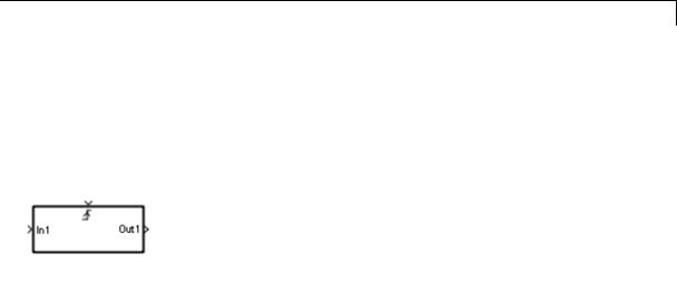
Description |
|
This block is a Subsystem block that is preconfigured to serve as the starting point for creating a triggered subsystem (see “Triggered Subsystems”).
2-1905

Trigonometric Function
Purpose |
Specified trigonometric function on input |
|
|
|||
Library |
Math Operations |
|
|
|
|
|
Description |
Supported Functions |
|
|
|
||
|
|
The Trigonometric Function block performs common trigonometric |
|
|||
|
|
functions. You can select one of the following functions from the |
|
|||
|
|
Function parameter list. |
|
|
|
|
|
|
|
|
|
|
|
|
|
Function |
Description |
Mathematical |
MATLAB |
|
|
|
|
|
Expression |
Equivalent |
|
|
|
sin |
Sine of the |
sin(u) |
sin |
|
|
|
|
input |
|
|
|
|
|
cos |
Cosine of the |
cos(u) |
cos |
|
|
|
|
input |
|
|
|
|
|
tan |
Tangent of the |
tan(u) |
tan |
|
|
|
|
input |
|
|
|
|
|
asin |
Inverse sine of |
asin(u) |
asin |
|
|
|
|
the input |
|
|
|
|
|
acos |
Inverse cosine |
acos(u) |
acos |
|
|
|
|
of the input |
|
|
|
|
|
atan |
Inverse tangent |
atan(u) |
atan |
|
|
|
|
of the input |
|
|
|
|
|
atan2 |
Four-quadrant |
atan2(u) |
atan2 |
|
|
|
|
inverse tangent |
|
|
|
|
|
|
of the input |
|
|
|
|
|
sinh |
Hyperbolic sine |
sinh(u) |
sinh |
|
|
|
|
of the input |
|
|
|
|
|
cosh |
Hyperbolic |
cosh(u) |
cosh |
|
|
|
|
cosine of the |
|
|
|
|
|
|
input |
|
|
|
2-1906

Trigonometric Function
|
Function |
Description |
Mathematical |
MATLAB |
|
|
|
|
Expression |
Equivalent |
|
|
tanh |
Hyperbolic |
tanh(u) |
tanh |
|
|
|
tangent of the |
|
|
|
|
|
input |
|
|
|
|
asinh |
Inverse |
asinh(u) |
asinh |
|
|
|
hyperbolic sine |
|
|
|
|
|
of the input |
|
|
|
|
acosh |
Inverse |
acosh(u) |
acosh |
|
|
|
hyperbolic |
|
|
|
|
|
cosine of the |
|
|
|
|
|
input |
|
|
|
|
atanh |
Inverse |
atanh(u) |
atanh |
|
|
|
hyperbolic |
|
|
|
|
|
tangent of the |
|
|
|
|
|
input |
|
|
|
|
sincos |
Sine of the |
— |
— |
|
|
|
input; cosine |
|
|
|
|
|
of the input |
|
|
|
|
cos + jsin |
Complex |
— |
— |
|
|
|
exponential of |
|
|
|
|
|
the input |
|
|
|
The block output is the result of applying the function to one or more inputs in radians. Each function supports:
•Scalar operations
•Element-wise vector and matrix operations
Note Not all compilers support the asinh, acosh, and atanh functions. If you use a compiler that does not support those functions, a warning appears and the generated code fails to link.
2-1907

Trigonometric Function
Block Appearance for the atan2 Function
If you select the atan2 function, the block shows two inputs. The first input is the y-axis or imaginary part of the function argument. The second input is the x-axis or real part of the function argument. (See “How to Rotate a Block” in the Simulink documentation for a description of the port order for various block orientations.)
Block Appearance for the sincos Function
If you select the sincos function, the block shows two outputs. The first output is the sine of the function argument, and the second output is the cosine of the function argument.
Effect of Out-of-Range Input on CORDIC Approximations
If you use the CORDIC approximation method (see “Definitions” on page 2-1909), the block input has the following restrictions:
•For signed fixed-point types, the input angle must fall within the range [–2π, 2π) radians.
•For unsigned fixed-point types, the input angle must fall within the range [0, 2π) radians.
The following table summarizes what happens for an out-of-range input.
|
Block Usage |
Effect of Out-of-Range Input |
|
|
Simulation |
An error appears. |
|
|
Generated code |
Undefined behavior occurs. |
|
|
Accelerator modes |
|
|
|
|
|
|
Ensure that you use an in-range input for the Trigonometric Function block when you use the CORDIC approximation, which is available for the sin, cos, sincos, and cos + jsin functions. Avoid relying on undefined behavior for generated code or Accelerator modes.
2-1908

Trigonometric Function
Definitions CORDIC
Data Type
Support
CORDIC is an acronym for COordinate Rotation DIgital Computer. The Givens rotation-based CORDIC algorithm is among one of the most hardware-efficient algorithms available because it requires only iterative shift-add operations (see [1], [2]) The CORDIC algorithm eliminates the need for explicit multipliers. Using CORDIC, you can calculate various functions, such as sine, cosine, arc sine, arc cosine, arc tangent, and vector magnitude. You can also use this algorithm for divide, square root, and hyperbolic, and logarithmic functions.
Increasing the number of CORDIC iterations can produce more accurate results, but doing so also increases the expense of the computation and adds latency.
The block accepts input signals of the following data types:
|
Functions |
Input Data Types |
|
|
• sin |
• Floating point |
|
|
• cos |
• Fixed point (only when |
|
|
• sincos |
Approximation method is |
|
|
CORDIC) |
|
|
|
• cos + jsin |
|
|
|
|
|
|
|
• tan |
• Floating point |
|
|
• asin |
|
|
|
• acos |
|
|
|
• atan |
|
|
|
• atan2 |
|
|
|
• sinh |
|
|
|
• cosh |
|
|
|
• tanh |
|
|
|
• asinh |
|
|
|
|
|
|
2-1909

Trigonometric Function
Functions |
Input Data Types |
|
|
•acosh
•atanh
The block output data type depends on the input data type and your selection for Approximation method:
|
Input Data |
Approximation |
Output Data Type |
|
|
Type |
Method |
|
|
|
Floating point |
None or CORDIC |
Same as input |
|
|
Fixed point |
CORDIC |
fixdt(1, WL, WL – 2) where WL |
|
|
|
|
is the input word length |
|
|
|
|
This fixed-point type |
|
|
|
|
provides the best precision |
|
|
|
|
for the CORDIC algorithm. |
|
The CORDIC approximation is available for the sin, cos, sincos, and cos + jsin functions.
Complex input signals are supported for all functions in this block, except atan2. The block output is real or complex, depending on your selection for Output signal type. This parameter is not available when you use the CORDIC approximation to compute block output. For CORDIC approximations, the output must be:
•Real for sin, cos, and sincos
•Complex for cos + jsin
2-1910

Trigonometric Function
Parameters and Dialog Box
Function
Specify the trigonometric function. The name of the function on the block icon changes to match your selection.
Approximation method
Specify the type of approximation for computing output. This parameter appears only when you set Function to sin, cos,
sincos, or cos + jsin.
2-1911
Trigonometric Function
|
Approximation |
Data Types |
When to Use This |
|
|
Method |
Supported |
Method |
|
|
None (default) |
Floating point |
You want to use |
|
|
|
|
the default Taylor |
|
|
|
|
series algorithm. |
|
|
CORDIC |
Floating point and |
You want a fast, |
|
|
|
fixed point |
approximate |
|
|
|
|
calculation. |
|
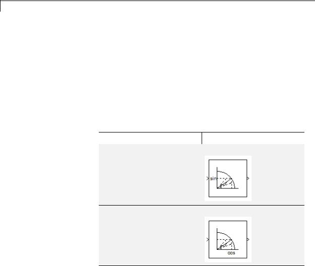
If you select CORDIC, the block icon changes:
Function |
Block Icon |
|
|
sin
cos
2-1912
Trigonometric Function
Function |
Block Icon |
|
|
sincos
cos + jsin
When you use the CORDIC approximation, follow these guidelines:
•For signed fixed-point types, the input angle must fall within the range [–2π, 2π) radians.
•For unsigned fixed-point types, the input angle must fall within the range [0, 2π) radians.
Number of iterations
Specify the number of iterations to perform the CORDIC algorithm. The default value is 11.
•When the block input uses a floating-point data type, the number of iterations can be a positive integer.
•When the block input is a fixed-point data type, the number of iterations cannot exceed the word length.
For example, if the block input is fixdt(1,16,15), the word length is 16. In this case, the number of iterations cannot exceed 16.
2-1913

Trigonometric Function
This parameter appears when both of the following conditions hold:
•You set Function to sin, cos, sincos, or cos + jsin.
•You set Approximation method to CORDIC.
Output signal type
Specify the output signal type of the Trigonometric Function block as auto, real, or complex.
Function |
Input |
Output Signal Type |
|||
|
Signal |
|
|
|
|
|
Auto |
Real |
Complex |
||
|
Type |
||||
|
|
|
|
||
Any |
real |
real |
real |
complex |
|
selection |
|
|
|
|
|
complex |
complex |
error |
complex |
||
for the |
|||||
|
|
|
|
||
Function |
|
|
|
|
|
parameter |
|
|
|
|
|
Note When Function is atan2, complex input signals are not supported for simulation or code generation.
Setting Approximation method to CORDIC disables this parameter.
Sample time (-1 for inherited)
Specify the time interval between samples. To inherit the sample time, set this parameter to -1. See “Specify Sample Time” in the Simulink documentation for more information.
2-1914
Trigonometric Function
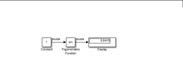
Examples sin Function with Floating-Point Input
Suppose that you have the following model:
The key block parameters for the Constant block are:
|
Parameter |
Setting |
|
|
|
Constant value |
1 |
|
|
|
Output data type |
Inherit: |
Inherit from |
|
|
|
'Constant |
value' |
|
|
|
|
|
|
The block parameters for the Trigonometric Function block are:
|
Parameter |
Setting |
|
|
Function |
sin |
|
|
Approximation method |
None |
|
|
Output signal type |
auto |
|
|
Sample time |
-1 |
|
|
|
|
|
The output type of the Trigonometric Function block is the same as the input because the input type is floating point and Approximation method is None.
2-1915
Trigonometric Function
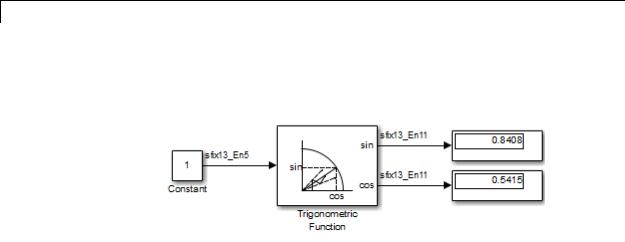
sincos Function with Fixed-Point Input
Suppose that you have the following model:
The key block parameters for the Constant block are:
|
Parameter |
Setting |
|
|
Constant value |
1 |
|
|
|
This value must fall within the |
|
|
|
range [–2π, 2π) because the |
|
|
|
Trigonometric Function block |
|
|
|
uses the CORDIC algorithm and |
|
|
|
the block input uses a signed |
|
|
|
fixed-point type. |
|
|
Output data type |
fixdt(1,13,5) |
|
|
|
|
|
The block parameters for the Trigonometric Function block are:
|
Parameter |
Setting |
|
|
Function |
sincos |
|
|
Approximation method |
CORDIC |
|
|
Number of iterations |
11 |
|
|
Sample time |
-1 |
|
|
|
|
|
2-1916
Trigonometric Function
The output type of the Trigonometric Function block is fixdt(1,13,11) because the input type is fixed point and Approximation method is CORDIC. The output fraction length equals the input word length – 2.
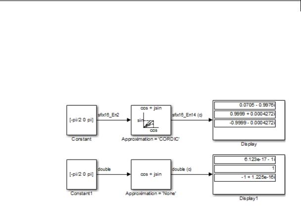
Block Behavior for Complex Exponential Output
The following model compares the complex exponential output for the two different approximation methods:
The key block parameters for the Constant blocks are:
|
Block |
Parameter |
Setting |
|
|
|
Constant |
Constant value |
[-pi/2 0 |
pi] |
|
|
|
Output data type |
fixdt(1,16,2) |
|
|
|
Constant1 |
Constant value |
[-pi/2 0 |
pi] |
|
|
|
Output data type |
double |
|
|
|
|
|
|
|
|
2-1917

Trigonometric Function
The block parameters for the Trigonometric Function blocks are:
|
Block |
Parameter |
Setting |
|
|
Approximation = |
Function |
cos + jsin |
|
|
'CORDIC' |
Approximation |
CORDIC |
|
|
|
|
||
|
|
method |
|
|
|
|
Number of |
11 |
|
|
|
iterations |
|
|
|
|
Sample time |
-1 |
|
|
Approximation = |
Function |
cos + jsin |
|
|
'None' |
Approximation |
None |
|
|
|
|
||
|
|
method |
|
|
|
|
Sample time |
-1 |
|
|
|
|
|
|
When the Approximation method is CORDIC, the input data type can be fixed point, in this case: fixdt(1,16,2). The output data type is fixdt(1,16,14) because the output fraction length equals the input word length – 2.
When the Approximation method is None, the input data type must be floating point. The output data type is the same as the input.
Characteristics |
Direct Feedthrough |
Yes |
|
Sample Time |
Inherited from the driving block |
|
Scalar Expansion |
Yes, of the input when the function |
|
|
requires two inputs |
|
Dimensionalized |
Yes |
|
Multidimensionalized |
Yes |
|
Zero-Crossing Detection |
No |
|
|
|
2-1918

Trigonometric Function
References
See Also
[1]Volder, J.E. “The CORDIC Trigonometric Computing Technique,”
IRE Transactions on Electronic Computers. Vol. EC-8, September 1959, pp. 330–334.
[2]Andraka, R. “A survey of CORDIC algorithm for FPGA based computers.” Proceedings of the 1998 ACM/SIGDA sixth international symposium on Field programmable gate arrays. Feb. 22–24, 1998, pp. 191–200.
Math Function, Sqrt
2-1919

Unary Minus
Purpose
Library
Description
Data Type
Support
Negate input
Math Operations
The Unary Minus block negates the input.
For signed-integer data types, the unary minus of the most negative value is not representable by the data type. In this case, the Saturate on integer overflow check box controls the behavior of the block:
|
If you... |
The block... |
And... |
|
|
Select this |
Saturates to the |
• For 8-bit signed integers, |
|
|
check box |
most positive value |
-128 maps to 127. |
|
|
|
of the integer data |
• For 16-bit signed integers, |
|
|
|
type |
-32768 maps to 32767. |
|
|
|
|
|
|
|
|
|
• For 32-bit signed integers, |
|
|
|
|
-2147483648 maps to |
|
|
|
|
2147483647. |
|
|
Do not select |
Wraps to the most |
• For 8-bit signed integers, |
|
|
this check box |
negative value of |
-128 remains -128. |
|
|
|
the integer data |
• For 16-bit signed integers, |
|
|
|
type |
|
|
|
|
-32768 remains -32768. |
|
|
|
|
|
|
|
|
|
|
• For 32-bit signed integers, |
|
|
|
|
-2147483648 remains |
|
|
|
|
-2147483648. |
|
The Unary Minus block accepts and outputs signals of the following data types:
•Floating point
•Signed integer
•Fixed point
2-1920
Unary Minus
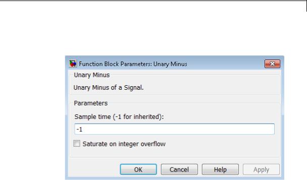
Parameters and Dialog Box
For more information, see “Data Types Supported by Simulink” in the Simulink documentation.
Sample time (-1 for inherited)
Specify the time interval between samples. To inherit the sample time, set this parameter to -1. For more information, see “Specify Sample Time” in the Simulink documentation.
Saturate on integer overflow
Select to have integer overflows saturate. Otherwise, overflows wrap.
When you select this check box, saturation applies to every internal operation on the block, not just the output or result. In general, the code generation process can detect when overflow is not possible. In this case, the code generator does not produce saturation code.
2-1921

Unary Minus
Characteristics |
Direct Feedthrough |
No |
|
Sample Time |
Specified in the Sample time |
|
|
parameter |
|
Scalar Expansion |
Yes, of input or initial conditions |
|
Dimensionalized |
Yes |
|
Multidimensionalized |
Yes |
|
Zero-Crossing Detection |
No |
|
|
|
2-1922
Uniform Random Number
Purpose |
Generate uniformly distributed random numbers |
Library |
Sources |
Description |
The Uniform Random Number block generates uniformly distributed |
|
random numbers over an interval that you specify. To generate |
|
normally distributed random numbers, use the Random Number block. |
|
You can generate a repeatable sequence using any Uniform Random |
|
Number block with the same nonnegative seed and parameters. The |
|
seed resets to the specified value each time a simulation starts. |
|
Avoid integrating a random signal, because solvers must integrate |
|
relatively smooth signals. Instead, use the Band-Limited White Noise |
|
block. |
|
The numeric parameters of this block must have the same dimensions |
|
after scalar expansion. If you select the Interpret vector parameters |
|
as 1-D check box and the numeric parameters are row or column vectors |
|
after scalar expansion, the block outputs a 1-D signal. If you clear the |
|
Interpret vector parameters as 1-D check box, the block outputs a |
|
signal of the same dimensionality as the parameters. |
Data Type |
The Uniform Random Number block accepts and outputs a real signal |
Support |
of type double. |
|
For more information, see “Data Types Supported by Simulink” in the |
|
Simulink documentation. |
2-1923
Uniform Random Number
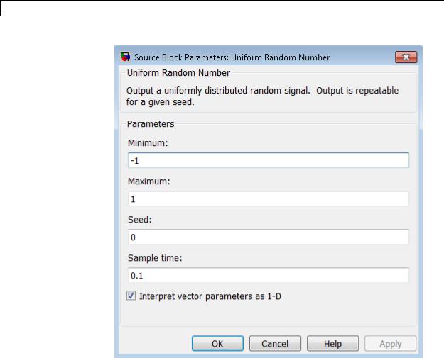
Parameters and Dialog Box
Minimum
Specify the minimum of the interval. The default is -1.
Maximum
Specify the maximum of the interval. The default is 1.
Seed
Specify the starting seed for the random number generator. The default is 0.
2-1924

Uniform Random Number
The seed must be 0 or a positive integer. Output is repeatable for a given seed.
Sample time
Specify the time interval between samples. The default is 0.1. See “Specify Sample Time” in the Simulink documentation for more information.
Interpret vector parameters as 1-D
If you select this check box and the other parameters are row or column vectors after scalar expansion, the block outputs a 1-D signal. Otherwise, the block outputs a signal of the same dimensionality as the other parameters. For more information, see “Determining the Output Dimensions of Source Blocks” in the Simulink documentation.
Characteristics |
|
Sample Time |
Specified in the Sample time |
|
|
|
parameter |
|
|
Scalar Expansion |
Yes, of parameters |
|
|
Dimensionalized |
Yes |
|
|
Multidimensionalized |
Yes |
|
|
Zero-Crossing Detection |
No |
See Also |
|
Random Number |
|
2-1925

Unit Delay
Purpose |
Delay signal one sample period |
|
Library |
Discrete |
|
Description |
The Unit Delay block holds and delays its input by the sample period |
|
|
you specify. This block is equivalent to the z-1 discrete-time operator. |
|
|
The block accepts one input and generates one output. Each signal can |
|
|
be scalar or vector. If the input is a vector, the block holds and delays |
|
|
all elements of the vector by the same sample period. |
|
|
You specify the block output for the first sampling period with the |
|
|
Initial conditions parameter. Careful selection of this parameter can |
|
|
minimize unwanted output behavior. You specify the time between |
|
|
samples with the Sample time parameter. A setting of -1 means the |
|
|
block inherits the Sample time. |
|
|
When the Unit Delay block inherits a continuous sample time, the block |
|
|
is analogous to the Memory block. |
|
|
|
|
|
Tip Do not use the Unit Delay block to create a slow-to-fast transition |
|
|
between blocks operating at different sample rates. Instead, use the |
|
|
Rate Transition block. |
|
Comparison |
Blocks with Similar Functionality |
|
with |
The Unit Delay, Memory, and Zero-Order Hold blocks provide similar |
|
Similar |
||
functionality but have different capabilities. Also, the purpose of each |
||
Blocks |
block is different. The sections that follow highlight some of these |
|
|
differences. |
2-1926

Unit Delay
Recommended Usage for Each Block
|
Block |
Purpose of the Block |
Reference Examples |
|
|
Unit Delay |
Implement a delay using |
• sldemo_enginewc |
|
|
|
a discrete sample time |
(Compression |
|
|
|
that you specify. Ideally, |
subsystem) |
|
|
|
the block accepts and |
|
|
|
|
outputs signals with a |
|
|
|
|
discrete sample time. |
|
|
|
Memory |
Implement a delay by |
• sldemo_bounce |
|
|
|
one integration time step. |
• sldemo_clutch |
|
|
|
Ideally, the block accepts |
(Friction Mode |
|
|
|
and outputs signals |
|
|
|
|
Logic/Lockup FSM |
|
|
|
|
where the sample time |
|
|
|
|
subsystem) |
|
|
|
|
is continuous or fixed in |
|
|
|
|
|
|
|
|
|
minor time step. For more |
|
|
|
|
information, see “Types |
|
|
|
|
of Sample Time” in the |
|
|
|
|
Simulink documentation. |
|
|
|
Zero-Order |
Convert an input signal |
• sldemo_radar_eml |
|
|
Hold |
with a continuous sample |
• aero_dap3dof |
|
|
|
time to an output signal |
|
|
|
|
with a discrete sample |
|
|
|
|
time. |
|
|
2-1927

Unit Delay
Overview of Block Capabilities
|
Capability |
|
Block |
|
|
|
|
Unit Delay |
Memory |
Zero-Order |
|
|
|
|
Hold |
|
|
|
|
|
|
|
|
|
Specification |
Yes |
Yes |
No, because the |
|
|
of initial |
|
|
block output at |
|
|
condition |
|
|
time t = 0 must |
|
|
|
|
|
match the input |
|
|
|
|
|
value. |
|
|
Specification |
Yes |
No, because the |
Yes |
|
|
of sample |
|
block can only |
|
|
|
time |
|
inherit sample |
|
|
|
|
|
time (from the |
|
|
|
|
|
driving block or |
|
|
|
|
|
the solver used |
|
|
|
|
|
for the entire |
|
|
|
|
|
model). |
|
|
|
Support for |
Yes |
No |
Yes |
|
|
frame-based |
|
|
|
|
|
signals |
|
|
|
|
|
Support for |
Yes |
No |
No |
|
|
state logging |
|
|
|
|
Effect of Solver Specification on Block Output
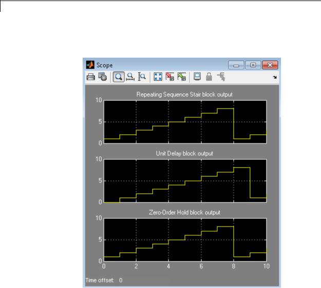
When you specify a discrete sample time in the dialog box for a Unit Delay or Zero-Order Hold block, the block output can differ depending on the solver specification for the model.
2-1928
Unit Delay
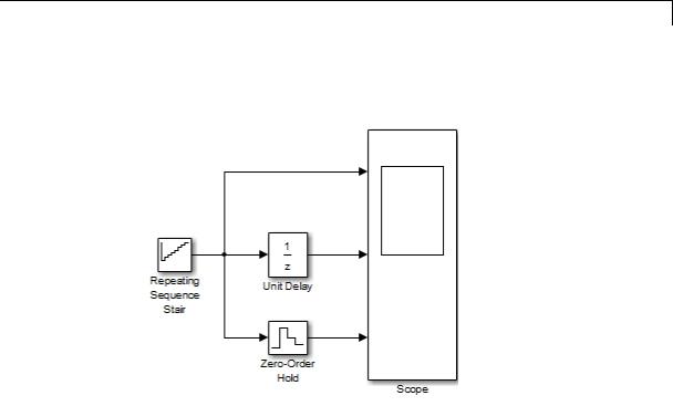
Suppose that you have a model with Unit Delay and Zero-Order Hold blocks, which both use a discrete sample time of 1:
The Repeating Sequence Stair block uses a continuous sample time of 0 to provide input signals to the Unit Delay and Zero-Order Hold blocks.
2-1929
Unit Delay
If the model uses a fixed-step solver with a step size of 1, the scope shows the following simulation results:
2-1930
Unit Delay
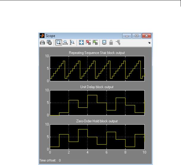
If the model uses a variable-step solver, the scope shows the following simulation results:
The Zero-Order Hold block takes the input value of the Repeating Sequence Stair block at t = 0, 1, 2, ... , 9 and holds each input value for a sample period (1 second). The Unit Delay block applies the same 1-second hold to each input value of the Repeating Sequence Stair block, but also delays each value by a sample period. The Initial conditions
2-1931

Unit Delay
Data Type
Support
parameter specifies the output for the Unit Delay block during the first sample period. For more information about sample time, see “What Is Sample Time?” and “Specify Sample Time”.
Solver specification for a model also affects the behavior of the Memory block. For details, see “Examples of Memory Block Usage” on page 2-949.
The Unit Delay block accepts real or complex signals of any data type that Simulink supports, including fixed-point and enumerated data types. If the data type of the input signal is user-defined, the initial condition must be zero.
For more information, see “Data Types Supported by Simulink” in the Simulink documentation.
2-1932
Unit Delay
Parameters and Dialog Box
2-1933

Unit Delay
During simulation, the block uses the following values:
•The initial value of the signal object to which the state name is resolved
•Min and Max values of the signal object
For more information, see “States” in the Simulink Coder documentation.
2-1934

Unit Delay
Initial condition
Specify the output of the simulation for the first sampling period, during which the output of the Unit Delay block is otherwise undefined.
Settings
Default: 0
The Initial conditions parameter is converted from a double to the input data type offline using round-to-nearest and saturation.
Command-Line Information
See “Block-Specific Parameters” on page 8-109 for the command-line information.
2-1935

Unit Delay
Input processing
Specify whether the Unit Delay block performs sampleor frame-based processing.
Settings
Default: Elements as channels (sample based)
Elements as channels (sample based)
Treat each element of the input as a separate channel (sample-based processing).
Columns as channels (frame based)
Treat each column of the input as a separate channel (frame-based processing).
Inherited
Sets the block to inherit the processing mode from the input signal and delay the input accordingly. You can identify whether the input signal is sample or frame based by looking at the signal line. Simulink represents sample-based signals with a single line and frame-based signals with a double line.
Note When you choose the Inherited option for the Input processing parameter, and the input signal is frame-based, Simulink® will generate a warning or error in future releases.
Use Input processing to specify whether the block performs sampleor frame-based processing. The block accepts frame-based signals for the input u. All other input signals must be sample based.
2-1936

Unit Delay
|
Input Signal u |
Input Processing |
Block Works? |
|
|
|
Mode |
|
|
|
Sample based |
Sample based |
Yes |
|
|
Frame based |
|
No, produces an |
|
|
|
|
error |
|
|
Sample based |
Frame based |
Yes |
|
|
Frame based |
|
Yes |
|
|
Sample based |
Inherited |
Yes |
|
|
Frame based |
|
Yes |
|
|
|
|
|
|
For more information about these two processing modes, see “Sampleand Frame-Based Concepts” in the DSP System Toolbox documentation.
Dependency
Frame-based processing requires a DSP System Toolbox license.
Command-Line Information
See “Block-Specific Parameters” on page 8-109 for the command-line information.
2-1937

Unit Delay
Sample time (-1 for inherited)
Enter the discrete interval between sample time hits or specify another appropriate sample time such as continuous or inherited.
Settings
Default: -1
By default, the block inherits its sample time based upon the context of the block within the model. To set a different sample time, enter a valid sample time based upon the table in “Types of Sample Time”.
See also “Specify Sample Time” in the online documentation for more information.
Command-Line Information
See “Block-Specific Parameters” on page 8-109 for the command-line information.
2-1938

Unit Delay
State name
Use this parameter to assign a unique name to each state.
Settings
Default: ' '
• If left blank, no name is assigned.
Tips
•A valid identifier starts with an alphabetic or underscore character, followed by alphanumeric or underscore characters.
•The state name applies only to the selected block.
Dependency
This parameter enables State name must resolve to Simulink signal object when you click the Apply button.
For more information, see “States” in the Simulink Coder documentation.
Command-Line Information
See “Block-Specific Parameters” on page 8-109 for the command-line information.
2-1939

Unit Delay
State name must resolve to Simulink signal object
Require that state name resolve to Simulink signal object.
Settings
Default: Off
 On
On
Require that state name resolve to Simulink signal object.
 Off
Off
Do not require that state name resolve to Simulink signal object.
Dependencies
State name enables this parameter.
Selecting this check box disables Code generation storage class.
Command-Line Information
See “Block-Specific Parameters” on page 8-109 for the command-line information.
2-1940

Unit Delay
Package
Select a package that defines the custom storage class you want to apply.
Settings
Default: ---None---
---None---
Sets internal storage class attributes.
mpt
Applies the built-in mpt package.
Simulink
Applies the built-in Simulink package.
Dependencies
If you have defined any packages of your own, click Refresh. This action adds all user-defined packages on your search path to the package list.
Command-Line Information
See “Block-Specific Parameters” on page 8-109 for the command-line information.
2-1941

Unit Delay
Code generation storage class
Select state storage class.
Settings
Default: Auto
Auto
Auto is the appropriate storage class for states that you do not need to interface to external code.
ExportedGlobal
State is stored in a global variable
ImportedExtern
model_private.h declares the state as an extern variable.
ImportedExternPointer
model_private.h declares the state as an extern pointer.
Dependencies
State name enables this parameter.
Setting this parameter to ExportedGlobal, ImportedExtern, or
ImportedExternPointer enables Code generation storage type qualifier.
Command-Line Information
See “Block-Specific Parameters” on page 8-109 for the command-line information.
See Also
“State Storage Classes” in the Simulink Coder documentation.
2-1942
Unit Delay
Code generation storage class (when Package is selected)
Select custom storage class for state.
Settings
Default: Auto
Auto
Auto is the appropriate storage class for states that you do not need to interface to external code.
SimulinkGlobal
model_P initializes the state to its corresponding value in the workspace.
ExportedGlobal
State is stored in a global variable
ImportedExtern
model_private.h declares the state as an extern variable.
ImportedExternPointer
model_private.h declares the state as an extern pointer.
Default
A non-editable placeholder storage class is created.
BitField
A struct declaration is created that embeds Boolean data.
Volatile
Volatile type qualifier is used in state declaration.
ExportToFile
Header (.h) file containing global variable declarations is generated with user-specified name.
ImportFromFile
Predefined header (.h) files containing global variable declarations are included.
2-1943

Unit Delay
FileScope
A static qualifier is generated in front of the state declaration to make the state visible only to the current file.
Struct
A struct declaration is created to encapsulate parameter or signal object data.
StructVolatile
Volatile type qualifier is used in struct declaration.
GetSet
Supports specialized function calls to read and write memory.
Dependencies
State name enables this parameter.
The list of valid storage classes differs based on the Package selection.
Setting this parameter to ExportedGlobal, ImportedExtern, or
ImportedExternPointer enables Code generation storage type qualifier.
Command-Line Information
See “Block-Specific Parameters” on page 8-109 for the command-line information.
See Also
“State Storage Classes” in the Simulink Coder documentation.
2-1944

Unit Delay
Bus
Support
Code generation storage type qualifier
Specify the Simulink Coder storage type qualifier.
Settings
Default: ' '
If left blank, no qualifier is assigned.
Dependency
Setting Code generation storage class to ExportedGlobal,
ImportedExtern, or ImportedExternPointer enables this parameter.
Command-Line Information
See “Block-Specific Parameters” on page 8-109 for the command-line information.
The Unit Delay block is a bus-capable block. The input can be a virtual or nonvirtual bus signal subject to the following restrictions:
•Initial conditions must be zero, a nonzero scalar, or a finite numeric structure.
•If Initial conditions is zero or a structure, and you specify a State name, the input cannot be a virtual bus.
•If Initial conditions is a nonzero scalar, no State name can be specified.
For information about specifying an initial condition structure, see “Specify Initial Conditions for Bus Signals”.
All signals in a nonvirtual bus input to a Unit Delay block must have the same sample time, even if the elements of the associated bus object specify inherited sample times. You can use a Rate Transition block to change the sample time of an individual signal, or of all signals in a bus. See “About Composite Signals” and Bus-Capable Blocks for more information.
2-1945

Unit Delay
Examples |
For an example of how to use the Unit Delay block, see the |
||
|
|
sldemo_enginewc model. The Unit Delay block appears in the |
|
|
|
Compression subsystem. |
|
Characteristics |
|
|
|
|
Bus-capable |
Yes, with restrictions as noted in “Bus |
|
|
|
|
Support” on page 2-1945 |
|
|
Direct Feedthrough |
No |
|
|
Sample Time |
Specified in the Sample time |
|
|
|
parameter |
|
|
Scalar Expansion |
Yes, of input or initial conditions |
|
|
States |
Yes, inherited from the driving block for |
|
|
|
nonfixed-point data types |
|
|
Dimensionalized |
Yes |
|
|
Multidimensionalized |
Yes |
|
|
Zero-Crossing Detection |
No |
See Also |
|
Memory, Zero-Order Hold |
|
2-1946

Unit Delay Enabled
Purpose |
Delay signal one sample period, if external enable signal is on |
Library |
Additional Math & Discrete / Additional Discrete |
Description |
The Unit Delay Enabled block delays a signal by one sample period |
|
when the external enable signal E is on. While the enable is off, the block |
|
is disabled. It holds the current state at the same value and outputs |
|
that value. The enable signal is on when E is not 0, and off when E is 0. |
|
You specify the block output for the first sampling period with the value |
|
of the Initial condition parameter. |
|
You specify the time between samples with the Sample time |
|
parameter. A setting of -1 means that the block inherits the Sample |
|
time. |
Data Type |
The Unit Delay Enabled block accepts signals of the following data |
Support |
types: |
|
• Floating point |
|
• Built-in integer |
|
• Fixed point |
|
• Boolean |
|
• Enumerated |
|
The output has the same data type as the input u. For enumerated |
|
signals, the Initial condition must be of the same enumerated type |
|
as the input u. |
|
For more information, see “Data Types Supported by Simulink” in the |
|
Simulink documentation. |
2-1947
Unit Delay Enabled
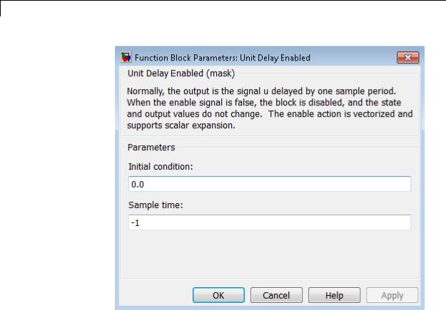
Parameters and
Dialog |
Initial condition |
|
Box |
Specify the initial output of the simulation. |
|
Sample time |
|
|
|
|
|
|
Specify the time interval between samples. To inherit the sample |
|
|
time, set this parameter to -1. See “Specify Sample Time” in the |
|
|
online documentation for more information. |
|
Characteristics |
|
|
Direct Feedthrough |
No |
|
|
Sample Time |
Specified in the Sample time |
|
|
parameter |
2-1948

Unit Delay Enabled
|
|
Scalar Expansion |
Yes |
|
|
Zero-Crossing Detection |
No |
See Also |
|
Unit Delay, Unit Delay Enabled External IC, Unit Delay Enabled |
|
|
|
Resettable, Unit Delay Enabled Resettable External IC, Unit Delay |
|
|
|
External IC, Unit Delay Resettable, Unit Delay Resettable External IC, |
|
|
|
Unit Delay With Preview Enabled, Unit Delay With Preview Enabled |
|
|
|
Resettable, Unit Delay With Preview Enabled Resettable External |
|
RV, Unit Delay With Preview Resettable, Unit Delay With Preview
Resettable External RV
2-1949

Unit Delay Enabled External IC
Purpose |
Delay signal one sample period, if external enable signal is on, with |
|
external initial condition |
Library |
Additional Math & Discrete / Additional Discrete |
Description |
The Unit Delay Enabled External IC block delays a signal by one |
|
sample period when the enable signal E is on. While the enable is off, |
|
the block holds the current state at the same value and outputs that |
|
value. The enable E is on when E is not 0, and off when E is 0. |
|
The initial condition of this block is given by the signal IC. |
|
You specify the time between samples with the Sample time |
|
parameter. A setting of -1 means the block inherits the Sample time. |
Data Type |
The Unit Delay Enabled External IC block accepts signals of the |
Support |
following data types: |
|
• Floating point |
|
• Built-in integer |
|
• Fixed point |
|
• Boolean |
|
The data types of the inputs u and IC must be the same. The output has |
|
the same data type as u and IC. |
|
For more information, see “Data Types Supported by Simulink” in the |
|
Simulink documentation. |
2-1950
Unit Delay Enabled External IC
Parameters and Dialog Box
Characteristics
Sample time
Specify the time interval between samples. To inherit the sample time, set this parameter to -1. See “Specify Sample Time” in the online documentation for more information.
Direct Feedthrough |
Yes, of the reset input port |
|
No, of the enable input port |
|
Yes, of the external IC port |
Sample Time |
Specified in the Sample time |
|
parameter |
Scalar Expansion |
Yes |
Zero-Crossing Detection |
No |
|
|
2-1951

Unit Delay Enabled External IC
See Also |
Unit Delay, Unit Delay Enabled, Unit Delay Enabled Resettable, Unit |
|
Delay Enabled Resettable External IC, Unit Delay External IC, Unit |
|
Delay Resettable, Unit Delay Resettable External IC, Unit Delay With |
|
Preview Enabled, Unit Delay With Preview Enabled Resettable, Unit |
|
Delay With Preview Enabled Resettable External RV, Unit Delay With |
|
Preview Resettable, Unit Delay With Preview Resettable External RV |
2-1952
Unit Delay Enabled Resettable
Purpose |
Delay signal one sample period, if external enable signal is on, with |
|
external Boolean reset |
Library |
Additional Math & Discrete / Additional Discrete |
Description |
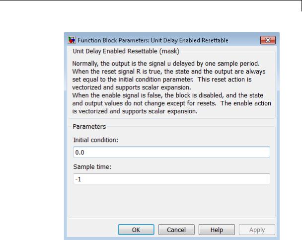
The Unit Delay Enabled Resettable block combines the features of the |
|
Unit Delay Enabled and Unit Delay Resettable blocks. |
|
The block can reset its state based on an external reset signal R. When |
|
the enable signal E is on and the reset signal R is false, the block outputs |
|
the input signal delayed by one sample period. |
|
When the enable signal E is on and the reset signal R is true, the block |
|
resets the current state to the initial condition, specified by the Initial |
|
condition parameter, and outputs that state delayed by one sample |
|
period. |
|
When the enable signal is off, the block is disabled, and the state and |
|
output do not change except for resets. The enable signal is on when E |
|
is not 0, and off when E is 0. |
|
You specify the time between samples with the Sample time |
|
parameter. A setting of -1 means that the block inherits the Sample |
|
time. |
Data Type |
The Unit Delay Enabled Resettable block accepts signals of the |
Support |
following data types: |
|
• Floating point |
|
• Built-in integer |
|
• Fixed point |
|
• Boolean |
|
• Enumerated |
2-1953

Unit Delay Enabled Resettable
The output has the same data type as the input u. For enumerated signals, the Initial condition must be of the same enumerated type as the input u.
For more information, see “Data Types Supported by Simulink” in the Simulink documentation.
2-1954
Unit Delay Enabled Resettable
Parameters and Dialog Box
Initial condition
Specify the initial output of the simulation.
Sample time
Specify the time interval between samples. To inherit the sample time, set this parameter to -1. See “Specify Sample Time” in the online documentation for more information.
2-1955

Unit Delay Enabled Resettable
Characteristics
See Also
Direct Feedthrough |
No, of the input port |
|
No, of the enable port |
|
Yes, of the reset port |
Sample Time |
Specified in the Sample time |
|
parameter |
Scalar Expansion |
Yes |
Zero-Crossing Detection |
No |
|
|
Unit Delay, Unit Delay Enabled, Unit Delay Enabled External IC, Unit Delay Enabled Resettable External IC, Unit Delay External IC, Unit Delay Resettable, Unit Delay Resettable External IC, Unit Delay With Preview Enabled, Unit Delay With Preview Enabled Resettable, Unit Delay With Preview Enabled Resettable External RV, Unit Delay With Preview Resettable, Unit Delay With Preview Resettable External RV
2-1956

Unit Delay Enabled Resettable External IC
Purpose |
Delay signal one sample period, if external enable signal is on, with |
|
external Boolean reset and initial condition |
Library |
Additional Math & Discrete / Additional Discrete |
Description |
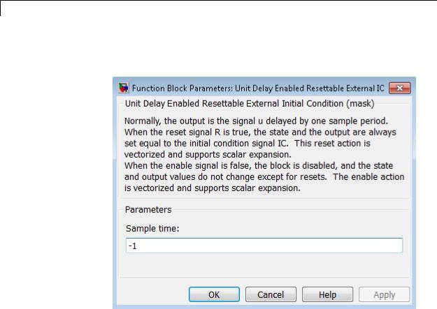
The Unit Delay Enabled Resettable External IC block combines the |
|
features of the Unit Delay Enabled, Unit Delay External IC, and Unit |
|
Delay Resettable blocks. |
|
The block can reset its state based on an external reset signal R. When |
|
the enable signal E is on and the reset signal R is false, the block outputs |
|
the input signal delayed by one sample period. |
|
When the enable signal E is on and the reset signal R is true, the block |
|
resets the current state to the initial condition given by the signal IC, |
|
and outputs that state delayed by one sample period. |
|
When the enable signal is off, the block is disabled, and the state and |
|
output do not change except for resets. The enable signal is on when E |
|
is not 0, and off when E is 0. |
|
You specify the time between samples with the Sample time |
|
parameter. A setting of -1 means that the block inherits the Sample |
|
time. |
Data Type |
The Unit Delay Enabled Resettable External IC block accepts signals of |
Support |
the following data types: |
|
• Floating point |
|
• Built-in integer |
|
• Fixed point |
|
• Boolean |
|
The data types of the inputs u and IC must be the same. The output has |
|
the same data type as u and IC. |
2-1957
Unit Delay Enabled Resettable External IC
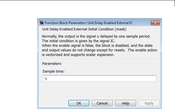
Parameters and Dialog Box
For more information, see “Data Types Supported by Simulink” in the Simulink documentation.
Sample time
Specify the time interval between samples. To inherit the sample time, set this parameter to -1. See “Specify Sample Time” in the online documentation for more information.
2-1958

Unit Delay Enabled Resettable External IC
Characteristics
See Also
Direct Feedthrough |
No, of the input port |
|
No, of the enable port |
|
Yes, of the enable port |
|
Yes, of the external IC port |
Sample Time |
Specified in the Sample time |
|
parameter |
Scalar Expansion |
Yes |
Zero-Crossing Detection |
No |
|
|
Unit Delay, Unit Delay Enabled, Unit Delay Enabled External IC, Unit Delay Enabled Resettable, Unit Delay External IC, Unit Delay Resettable, Unit Delay Resettable External IC, Unit Delay With Preview Enabled, Unit Delay With Preview Enabled Resettable, Unit Delay With Preview Enabled Resettable External RV, Unit Delay With Preview Resettable, Unit Delay With Preview Resettable External RV
2-1959

Unit Delay External IC
Purpose |
Delay signal one sample period, with external initial condition |
Library |
Additional Math & Discrete / Additional Discrete |
Description |
The Unit Delay External IC block delays its input by one sample period. |
|
This block is equivalent to the z-1 discrete-time operator. The block |
|
accepts one input and generates one output, both of which can be scalar |
|
or vector. If the input is a vector, all elements of the vector are delayed |
|
by the same sample period. |
|
The block’s output for the first sample period is equal to the signal IC. |
|
You specify the time between samples with the Sample time |
|
parameter. A setting of -1 means that the block inherits the Sample |
|
time. |
Data Type |
The Unit Delay External IC block accepts signals of the following data |
Support |
types: |
|
• Floating point |
|
• Built-in integer |
|
• Fixed point |
|
• Boolean |
|
The data types of the inputs u and IC must be the same. The output has |
|
the same data type as u and IC. |
|
For more information, see “Data Types Supported by Simulink” in the |
|
Simulink documentation. |
2-1960
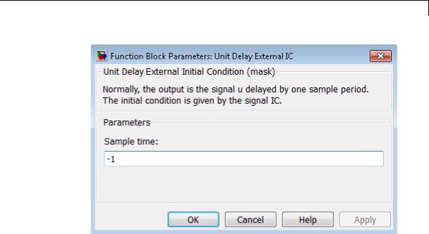
Unit Delay External IC
Parameters and Dialog Box
Characteristics
See Also
Sample time
Specify the time interval between samples. To inherit the sample time, set this parameter to -1. See “Specify Sample Time” in the online documentation for more information.
Direct Feedthrough |
No, of the input port |
|
Yes, of the external IC port |
Sample Time |
Specified in the Sample time |
|
parameter |
Scalar Expansion |
Yes |
Zero-Crossing Detection |
No |
|
|
Unit Delay, Unit Delay Enabled, Unit Delay Enabled External IC, Unit Delay Enabled Resettable, Unit Delay Enabled Resettable External IC, Unit Delay Resettable, Unit Delay Resettable External IC, Unit Delay With Preview Enabled, Unit Delay With Preview Enabled Resettable,
2-1961

Unit Delay External IC
Unit Delay With Preview Enabled Resettable External RV, Unit Delay With Preview Resettable, Unit Delay With Preview Resettable External RV
2-1962
Unit Delay Resettable
Purpose |
Delay signal one sample period, with external Boolean reset |
Library |
Additional Math & Discrete / Additional Discrete |
Description |
The Unit Delay Resettable block delays a signal one sample period. |
|
The block can reset both its state and output based on an external reset |
|
signal R. The block has two input ports, one for the input signal u and |
|
the other for the external reset signal R. |
|
At the start of simulation, the block’s Initial condition parameter |
|
determines its initial output. During simulation, when the reset signal |
|
is false, the block outputs the input signal delayed by one time step. |
|
When the reset signal is true, the block resets the current state and its |
|
output to the Initial condition. |
|
You specify the time between samples with the Sample time |
|
parameter. A setting of -1 means that the block inherits the Sample |
|
time. |
Data Type |
The Unit Delay Resettable block accepts signals of the following data |
Support |
types: |
|
• Floating point |
|
• Built-in integer |
|
• Fixed point |
|
• Boolean |
|
• Enumerated |
|
The output has the same data type as the input u. For enumerated |
|
signals, the Initial condition must be of the same enumerated type |
|
as the input u. |
|
For more information, see “Data Types Supported by Simulink” in the |
|
Simulink documentation. |
2-1963
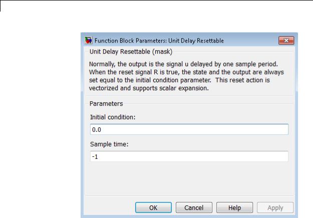
Unit Delay Resettable
Parameters and Dialog Box
Initial condition
Specify the initial output of the simulation.
Sample time
Specify the time interval between samples. To inherit the sample time, set this parameter to -1. See “Specify Sample Time” in the online documentation for more information.
2-1964

Unit Delay Resettable
Characteristics
See Also
Direct Feedthrough |
No, of the input port |
|
Yes, of the reset port |
Sample Time |
Specified in the Sample time |
|
parameter |
Scalar Expansion |
Yes |
Zero-Crossing Detection |
No |
|
|
Unit Delay, Unit Delay Enabled, Unit Delay Enabled External IC, Unit Delay Enabled Resettable, Unit Delay Enabled Resettable External IC, Unit Delay External IC, Unit Delay Resettable External IC, Unit Delay With Preview Enabled, Unit Delay With Preview Enabled Resettable, Unit Delay With Preview Enabled Resettable External RV, Unit Delay With Preview Resettable, Unit Delay With Preview Resettable External RV
2-1965

Unit Delay Resettable External IC
Purpose |
Delay signal one sample period, with external Boolean reset and initial |
|
condition |
Library |
Additional Math & Discrete / Additional Discrete |
Description |
The Unit Delay Resettable External IC block delays a signal one sample |
|
period. |
|
The block can reset its state based on an external reset signal R. The |
|
block has two input ports, one for the input signal u and the other for |
|
the reset signal R. When the reset signal is false, the block outputs the |
|
input signal delayed by one time step. When the reset signal is true, the |
|
block resets the current state to the initial condition given by the signal |
|
IC and outputs that state delayed by one time step. |
|
You specify the time between samples with the Sample time |
|
parameter. A setting of -1 means that the block inherits the Sample |
|
time. |
Data Type |
The Unit Delay Resettable External IC block accepts signals of the |
Support |
following data types: |
|
• Floating point |
|
• Built-in integer |
|
• Fixed point |
|
• Boolean |
|
The data types of the inputs u and IC must be the same. The output has |
|
the same data type as u and IC. |
|
For more information, see “Data Types Supported by Simulink” in the |
|
Simulink documentation. |
2-1966
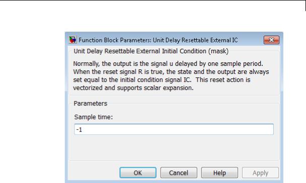
Unit Delay Resettable External IC
Parameters and Dialog Box
Characteristics
Sample time
Specify the time interval between samples. To inherit the sample time, set this parameter to -1. See “Specify Sample Time” in the online documentation for more information.
Direct Feedthrough |
No, of the input port |
|
Yes, of the reset port |
|
Yes, of the external IC port |
Sample Time |
Specified in the Sample time |
|
parameter |
Scalar Expansion |
Yes |
Zero-Crossing Detection |
No |
|
|
2-1967

Unit Delay Resettable External IC
See Also |
Unit Delay, Unit Delay Enabled, Unit Delay Enabled External IC, Unit |
|
Delay Enabled Resettable, Unit Delay Enabled Resettable External |
|
IC, Unit Delay External IC, Unit Delay Resettable, Unit Delay With |
|
Preview Enabled, Unit Delay With Preview Enabled Resettable, Unit |
|
Delay With Preview Enabled Resettable External RV, Unit Delay With |
|
Preview Resettable, Unit Delay With Preview Resettable External RV |
2-1968

Unit Delay With Preview Enabled
Purpose |
Output signal and signal delayed by one sample period, if external |
|
enable signal is on |
Library |
Additional Math & Discrete / Additional Discrete |
Description |
The Unit Delay With Preview Enabled block supports calculations that |
|
have feedback and depend on the current input. |
|
The block has two input ports: one for the input signal u and one for the |
|
external enable signal E. |
|
When the enable signal E is on, the first port outputs the signal and the |
|
second port outputs the signal delayed by one sample period. When the |
|
enable signal E is off, the block is disabled, and the state and output |
|
values do not change, except during resets. |
|
The enable signal is on when E is not 0, and off when E is 0. This enable |
|
action is vectorized and supports scalar expansion. |
|
Having two outputs is useful for implementing recursive calculations |
|
where the result includes the most recent inputs. The second output |
|
can feed back into calculations of the block’s inputs without causing an |
|
algebraic loop. Meanwhile, the first output shows the most up-to-date |
|
calculations. |
|
You specify the block output for the first sampling period with the value |
|
of the Initial condition parameter. |
|
You specify the time between samples with the Sample time |
|
parameter. A setting of -1 means that the block inherits the Sample |
|
time. |
Data Type |
The Unit Delay With Preview Enabled block accepts signals of the |
Support |
following data types: |
|
• Floating point |
|
• Built-in integer |
|
• Fixed point |
2-1969

Unit Delay With Preview Enabled
•Boolean
•Enumerated
The outputs have the same data type as the input u. For enumerated signals, the Initial condition must be of the same enumerated type as the input u.
For more information, see “Data Types Supported by Simulink” in the Simulink documentation.
2-1970

Unit Delay With Preview Enabled
Parameters and Dialog Box
Initial condition
Specify the initial output of the simulation.
Sample time
Specify the time interval between samples. To inherit the sample time, set this parameter to -1. See “Specify Sample Time” in the online documentation for more information.
2-1971

Unit Delay With Preview Enabled
Characteristics
See Also
Direct Feedthrough |
Yes, to first output port |
|
No, to second output port |
Sample Time |
Specified in the Sample time |
|
parameter |
Scalar Expansion |
Yes |
Zero-Crossing Detection |
No |
|
|
Unit Delay, Unit Delay Enabled, Unit Delay Enabled External IC, Unit Delay Enabled Resettable, Unit Delay Enabled Resettable External IC, Unit Delay External IC, Unit Delay Resettable, Unit Delay Resettable External IC, Unit Delay With Preview Enabled Resettable, Unit Delay With Preview Enabled Resettable External RV, Unit Delay With Preview Resettable, Unit Delay With Preview Resettable External RV
2-1972
Unit Delay With Preview Enabled Resettable
Purpose |
Output signal and signal delayed by one sample period, if external |
|
enable signal is on, with external reset |
Library |
Additional Math & Discrete / Additional Discrete |
Description |
The Unit Delay With Preview Enabled Resettable block supports |
|
calculations that have feedback and depend on the current input. The |
|
block can reset its state based on a reset signal R. |
|
The block has three input ports: one for the input signal u, one for the |
|
external enable signal E, and one for the external reset signal R. |
|
When the enable signal E is on and the reset signal R is false, the first |
|
port outputs the signal and the second port outputs the signal delayed |
|
by one sample period. |
|
When the enable signal E is on and the reset signal R is true, the block |
|
resets the current state to the initial condition given by the Initial |
|
condition parameter. The first output signal is forced to equal the |
|
initial condition. The second output signal is not affected until one |
|
time step later. |
|
When the enable signal is off, the block is disabled, and the state and |
|
output values do not change, except during resets. |
|
The enable signal is on when E is not 0, and off when E is 0. The enable |
|
and reset actions are vectorized and support scalar expansion. |
|
Having two outputs is useful for implementing recursive calculations |
|
where the result includes the most recent inputs. The second output |
|
can feed back into calculations of the block’s inputs without causing an |
|
algebraic loop. Meanwhile, the first output shows the most up-to-date |
|
calculations. |
|
You specify the time between samples with the Sample time |
|
parameter. A setting of -1 means that the block inherits the Sample |
|
time. |
2-1973

Unit Delay With Preview Enabled Resettable
Data Type
Support
The Unit Delay With Preview Enabled Resettable block accepts signals of the following data types:
•Floating point
•Built-in integer
•Fixed point
•Boolean
•Enumerated
The outputs have the same data type as the input u. For enumerated signals, the Initial condition must be of the same enumerated type as the input u.
For more information, see “Data Types Supported by Simulink” in the Simulink documentation.
2-1974
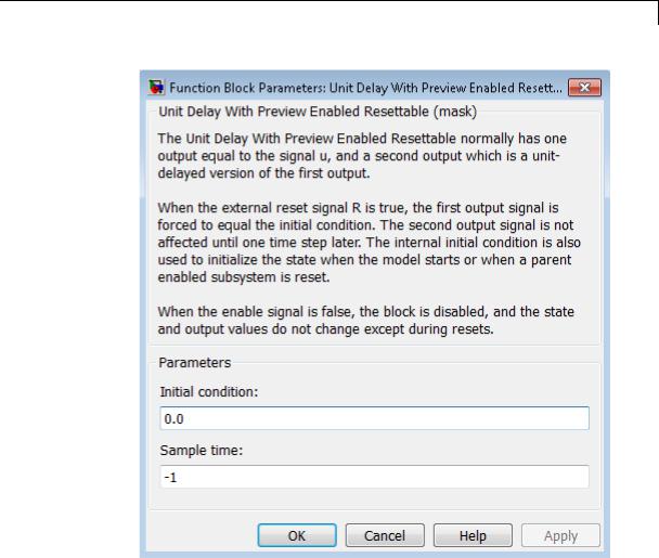
Unit Delay With Preview Enabled Resettable
Parameters and Dialog Box
Initial condition
Specify the initial output of the simulation.
Sample time
Specify the time interval between samples. To inherit the sample time, set this parameter to -1. See “Specify Sample Time” in the online documentation for more information.
2-1975

Unit Delay With Preview Enabled Resettable
Characteristics
See Also
Direct Feedthrough |
Yes, to first output port |
|
No, to second output port |
Sample Time |
Specified in the Sample time |
|
parameter |
Scalar Expansion |
Yes |
Zero-Crossing Detection |
No |
|
|
Unit Delay, Unit Delay Enabled, Unit Delay Enabled External IC, Unit Delay Enabled Resettable, Unit Delay Enabled Resettable External IC, Unit Delay External IC, Unit Delay Resettable, Unit Delay Resettable External IC, Unit Delay With Preview Enabled, Unit Delay With Preview Enabled Resettable External RV, Unit Delay With Preview Resettable, Unit Delay With Preview Resettable External RV
2-1976

Unit Delay With Preview Enabled Resettable External
RV
Purpose |
Output signal and signal delayed by one sample period, if external |
|
enable signal is on, with external RV reset |
Library |
Additional Math & Discrete / Additional Discrete |
Description |
The Unit Delay With Preview Enabled Resettable External RV block |
|
supports calculations that have feedback and depend on the current |
|
input. The block can reset its state based on a reset signal R. |
|
The block has four input ports: one for the input signal u, one for the |
|
external enable signal E, one for the external reset signal R, and one for |
|
the external reset value RV. |
|
When the enable signal E is on and the reset signal R is false, the first |
|
port outputs the signal and the second port outputs the signal delayed |
|
by one sample period. |
|
When the enable signal E is on and the reset signal R is true, the first |
|
output signal is forced to equal the reset value RV. The second output |
|
signal is not affected until one time step later, at which time it is equal |
|
to the reset value RV at the previous time step. The internal Initial |
|
condition has a direct effect on the second output only when the model |
|
starts or when a parent enabled subsystem is reset. |
|
When the enable signal is off, the block is disabled, and the state and |
|
output values do not change, except during resets. |
|
The enable signal is on when E is not 0, and off when E is 0. The enable |
|
and reset actions are vectorized and support scalar expansion. |
|
Having two outputs is useful for implementing recursive calculations |
|
where the result includes the most recent inputs. The second output |
|
can feed back into calculations of the block’s inputs without causing an |
|
algebraic loop. Meanwhile, the first output shows the most up-to-date |
|
calculations. |
|
You specify the time between samples with the Sample time |
|
parameter. A setting of -1 means that the block inherits the Sample |
|
time. |
2-1977

Unit Delay With Preview Enabled Resettable External RV
Data Type
Support
The Unit Delay With Preview Enabled Resettable External RV block accepts signals of the following data types:
•Floating point
•Built-in integer
•Fixed point
•Boolean
•Enumerated
The outputs have the same data type as the input u. For enumerated signals, the Initial condition must be of the same enumerated type as the input u.
For more information, see “Data Types Supported by Simulink” in the Simulink documentation.
2-1978

Unit Delay With Preview Enabled Resettable External
RV
Parameters and Dialog Box
Initial condition
Specify the initial output of the simulation.
Sample time
Specify the time interval between samples. To inherit the sample time, set this parameter to -1. See “Specify Sample Time” in the online documentation for more information.
2-1979

Unit Delay With Preview Enabled Resettable External RV
Characteristics
See Also
Direct Feedthrough |
Yes, to first output port |
|
No, to second output port |
Sample Time |
Specified in the Sample time |
|
parameter |
Scalar Expansion |
Yes |
Zero-Crossing Detection |
No |
|
|
Unit Delay, Unit Delay Enabled, Unit Delay Enabled External IC, Unit Delay Enabled Resettable, Unit Delay Enabled Resettable External IC, Unit Delay External IC, Unit Delay Resettable, Unit Delay Resettable External IC, Unit Delay With Preview Enabled, Unit Delay With Preview Enabled Resettable, Unit Delay With Preview Resettable, Unit Delay With Preview Resettable External RV
2-1980

Unit Delay With Preview Resettable
Purpose |
Output signal and signal delayed by one sample period, with external |
|
reset |
Library |
Additional Math & Discrete / Additional Discrete |
Description |
The Unit Delay With Preview Resettable block supports calculations |
|
that have feedback and depend on the current input. The block can |
|
reset its state based on a reset signal R. |
|
The block has two input ports: one for the input signal u and one for |
|
the external reset signal R. |
|
When the reset signal R is false, the first port outputs the signal and the |
|
second port outputs the signal delayed by one sample period. |
|
When the reset signal R is true, the block resets the current state to the |
|
initial condition given by the Initial condition parameter. The first |
|
output signal is forced to equal the initial condition. The second output |
|
signal is not affected until one time step later. |
|
This reset action is vectorized and supports scalar expansion. |
|
Having two outputs is useful for implementing recursive calculations |
|
where the result includes the most recent inputs. The second output |
|
can feed back into calculations of the block’s inputs without causing an |
|
algebraic loop. Meanwhile, the first output shows the most up-to-date |
|
calculations. |
|
You specify the time between samples with the Sample time |
|
parameter. A setting of -1 means that the block inherits the Sample |
|
time. |
Data Type |
The Unit Delay With Preview Resettable block accepts signals of the |
Support |
following data types: |
|
• Floating point |
|
• Built-in integer |
|
• Fixed point |
2-1981

Unit Delay With Preview Resettable
•Boolean
•Enumerated
The outputs have the same data type as the input u. For enumerated signals, the Initial condition must be of the same enumerated type as the input u.
For more information, see “Data Types Supported by Simulink” in the Simulink documentation.
2-1982
Unit Delay With Preview Resettable
Parameters and Dialog Box
Initial condition
Specify the initial output of the simulation.
Sample time
Specify the time interval between samples. To inherit the sample time, set this parameter to -1. See “Specify Sample Time” in the online documentation for more information.
2-1983

Unit Delay With Preview Resettable
Characteristics
See Also
Direct Feedthrough |
Yes, to first output port |
|
No, to second output port |
Sample Time |
Specified in the Sample time |
|
parameter |
Scalar Expansion |
Yes |
Zero-Crossing Detection |
No |
|
|
Unit Delay, Unit Delay Enabled, Unit Delay Enabled External IC, Unit Delay Enabled Resettable, Unit Delay Enabled Resettable External IC, Unit Delay External IC, Unit Delay Resettable, Unit Delay Resettable External IC, Unit Delay With Preview Enabled, Unit Delay With Preview Enabled Resettable, Unit Delay With Preview Enabled Resettable External RV, Unit Delay With Preview Resettable External RV
2-1984

Unit Delay With Preview Resettable External RV
Purpose |
Output signal and signal delayed by one sample period, with external |
|
RV reset |
Library |
Additional Math & Discrete / Additional Discrete |
Description |
The Unit Delay With Preview Resettable External RV block supports |
|
calculations that have feedback and depend on the current input. The |
|
block can reset its state based on a reset signal R. |
|
The block has three input ports: one for the input signal u, one for the |
|
external reset signal R, and one for the external reset value RV. |
|
When the reset signal R is false, the first port outputs the signal and the |
|
second port outputs the signal delayed by one sample period. |
|
When the reset signal R is true, the first output signal is forced to equal |
|
the reset value RV. The second output signal is not affected until one |
|
time step later, at which time it is equal to the reset value RV at the |
|
previous time step. The internal Initial condition has a direct effect |
|
on the second output only when the model starts or when a parent |
|
enabled subsystem is reset. |
|
This reset action is vectorized and supports scalar expansion. |
|
Having two outputs is useful for implementing recursive calculations |
|
where the result includes the most recent inputs. The second output |
|
can feed back into calculations of the block’s inputs without causing an |
|
algebraic loop. Meanwhile, the first output shows the most up-to-date |
|
calculations. |
|
You specify the time between samples with the Sample time |
|
parameter. A setting of -1 means that the block inherits the Sample |
|
time. |
Data Type |
The Unit Delay With Preview Resettable External RV block accepts |
Support |
signals of the following data types: |
|
• Floating point |
|
• Built-in integer |
2-1985

Unit Delay With Preview Resettable External RV
•Fixed point
•Boolean
•Enumerated
The outputs have the same data type as the input u. For enumerated signals, the Initial condition must be of the same enumerated type as the input u.
For more information, see “Data Types Supported by Simulink” in the Simulink documentation.
2-1986
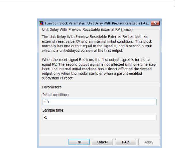
Unit Delay With Preview Resettable External RV
Parameters and Dialog Box
Initial condition
Specify the initial output of the simulation.
Sample time
Specify the time interval between samples. To inherit the sample time, set this parameter to -1. See “Specify Sample Time” in the online documentation for more information.
2-1987

Unit Delay With Preview Resettable External RV
Characteristics
See Also
Direct Feedthrough |
Yes, to first output port |
|
No, to second output port |
Sample Time |
Specified in the Sample time |
|
parameter |
Scalar Expansion |
Yes |
Zero-Crossing Detection |
No |
|
|
Unit Delay, Unit Delay Enabled, Unit Delay Enabled External IC, Unit Delay Enabled Resettable, Unit Delay Enabled Resettable External IC, Unit Delay External IC, Unit Delay Resettable, Unit Delay Resettable External IC, Unit Delay With Preview Enabled, Unit Delay With Preview Enabled Resettable, Unit Delay With Preview Enabled Resettable External RV, Unit Delay With Preview Resettable
2-1988
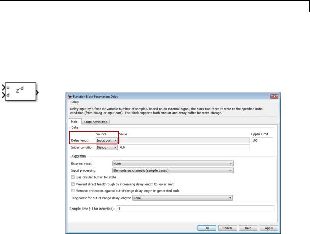
Variable Integer Delay
Purpose
Library
Description
See Also
Delay input signal by variable sample period
Discrete
The Variable Integer Delay block is a variant of the Delay block that has the source of the delay length set to Input port, by default.
•Delay
•Resettable Delay
2-1989
Variable Time Delay, Variable Transport Delay
Purpose |
Delay input by variable amount of time |
Library Continuous
Description The Variable Transport Delay and Variable Time Delay appear as two blocks in the Simulink block library. However, they are the same Simulink block with different settings of a Select delay type parameter. Use this parameter to specify the mode in which the block operates.
Variable Time Delay
In this mode, the block has a data input, a time delay input, and a data output. (See “How to Rotate a Block” in the Simulink documentation for a description of the port order for various block orientations.) The output at the current time step equals the value of its data input at a previous time equal to the current simulation time minus a delay time specified by the time delay input.
y(t) = u(t − t0 ) = u(t − τ(t))
|
u(t) |
|
|
C− |
τ(t) |
y(t) = u(t − τ(t)) |
|
C− |
To |
||
|
Variable
Time Delay
During the simulation, the block stores time and input value pairs in an internal buffer. At the start of simulation, the block outputs the value of the Initial output parameter until the simulation time exceeds the time delay input. Then, at each simulation step, the block outputs the signal at the time that corresponds to the current simulation time minus the delay time.
When you want the output at a time that does not correspond to times of the stored input values and the solver is a continuous solver, the block interpolates linearly between points. If the time delay is smaller than the step size, the block extrapolates an output point from a previous
2-1990
Variable Time Delay, Variable Transport Delay
point. For example, consider a fixed-step simulation with a step size of 1 and the current time at t = 5. If the delay is 0.5, the block needs to generate a point at t = 4.5. Because the most recent stored time value is at t = 4, the block extrapolates the input at 4.5 from the input at 4 and uses the extrapolated value as its output at t = 5.
Extrapolating forward from the previous time step can produce a less accurate result than extrapolating back from the current time step. However, the block cannot use the current input to calculate its output value because the input port does not have direct feedthrough.
If the model specifies a discrete solver, the block does not interpolate between time steps. Instead, it returns the nearest stored value that precedes the required value.
Variable Transport Delay
In this mode, the block output at the current time step is equal to the value of its data (top, or left) input at an earlier time equal to the current time minus a transportation delay.
y(t) = u(t − td (t))
Simulink software finds the transportation delay, td (t) , by solving the following equation:
t |
|
|
1 |
|
∫t−td |
|
|
|
dτ = 1 |
(t) t |
(τ) |
|||
|
|
i |
|
|
This equation involves an instantaneous time delay, ti(t) , given by the time delay (bottom, or right) input.
|
u(t) |
C− |
y(t) = u(t − td(t)) |
1 |
ti(t) |
Ti |
Variable
Transport Delay
2-1991

Variable Time Delay, Variable Transport Delay
Data Type
Support
Parameters and Dialog Box
For example, suppose you want to use this block to model the flow of a fluid through a pipe where the speed of the flow varies with time. In this case, the time delay input to the block would be
ti(t) = L vi(t)
where L is the length of the pipe and vi(t) is the speed of the fluid.
The Variable Time Delay and Variable Transport Delay blocks accept and output real signals of type double.
For more information, see “Data Types Supported by Simulink” in the Simulink documentation.
The parameters and dialog box differ, based on the mode in which the block is operating: variable time or variable transport. Most parameters exist in both modes.
The dialog box for the Variable Time Delay block appears as follows.
2-1992
Variable Time Delay, Variable Transport Delay
2-1993

Variable Time Delay, Variable Transport Delay
The dialog box for the Variable Transport Delay block appears as follows.
2-1994
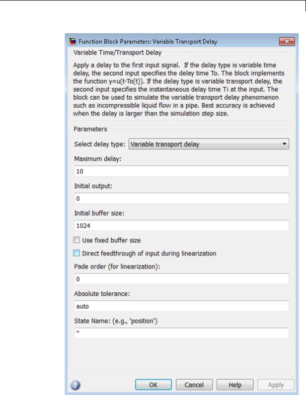
Variable Time Delay, Variable Transport Delay
2-1995

Variable Time Delay, Variable Transport Delay
Select delay type
Specify the mode in which the block operates.
Settings
Default: The Variable Time Delay block has a default value of Variable time delay. The Variable Transport Delay block has a default value of Variable transport delay.
Variable time delay
Specifies a Variable Time Delay block.
Variable transport delay
Specifies a Variable Transport Delay block.
Dependencies
Setting this parameter to Variable time delay enables the Handle zero delay parameter.
Setting this parameter to Variable transport delay enables the
Absolute tolerance and State Name parameters.
Command-Line Information
See “Block-Specific Parameters” on page 8-109 for the command-line information.
2-1996

Variable Time Delay, Variable Transport Delay
Maximum delay
Set the maximum value of the time delay input.
Settings
Default: 10
•This value defines the largest time delay input that this block allows. The block clips any delay that exceeds this value.
•This value cannot be negative. If the time delay becomes negative, the block clips it to zero and issues a warning message.
Command-Line Information
See “Block-Specific Parameters” on page 8-109 for the command-line information.
2-1997

Variable Time Delay, Variable Transport Delay
Initial output
Specify the output that the block generates until the simulation time first exceeds the time delay input.
Settings
Default: 0
The initial output of this block cannot be inf or NaN.
Command-Line Information
See “Block-Specific Parameters” on page 8-109 for the command-line information.
2-1998

Variable Time Delay, Variable Transport Delay
Initial buffer size
Define the initial memory allocation for the number of input points to store.
Settings
Default: 1024
•If the number of input points exceeds the initial buffer size, the block allocates additional memory.
•After simulation ends, a message shows the total buffer size needed.
Tips
•Because allocating memory slows down simulation, choose this value carefully if simulation speed is an issue.
•For long time delays, this block might use a large amount of memory, particularly for dimensionalized input.
Command-Line Information
See “Block-Specific Parameters” on page 8-109 for the command-line information.
2-1999

Variable Time Delay, Variable Transport Delay
Use fixed buffer size
Specify use of a fixed-size buffer to save input data from previous time steps.
Settings
Default: Off
 On
On
The block uses a fixed-size buffer.
 Off
Off
The block does not use a fixed-size buffer.
The Initial buffer size parameter specifies the buffer’s size. If the buffer is full, new data replaces data already in the buffer. Simulink software uses linear extrapolation to estimate output values that are not in the buffer.
Note ERT or GRT code generation uses a fixed-size buffer even if you do not select this check box.
Tips
•If the input data is linear, selecting this check box can save memory.
•If the input data is nonlinear, do not select this check box. Doing so might yield inaccurate results.
Command-Line Information
See “Block-Specific Parameters” on page 8-109 for the command-line information.
2-2000

Variable Time Delay, Variable Transport Delay
Handle zero delay
Convert this block to a direct feedthrough block.
Settings
Default: Off
 On
On
The block uses direct feedthrough.
 Off
Off
The block does not use direct feedthrough.
Dependency
Setting Select delay type to Variable time delay enables this parameter.
Command-Line Information
See “Block-Specific Parameters” on page 8-109 for the command-line information.
2-2001

Variable Time Delay, Variable Transport Delay
Direct feedthrough of input during linearization
Cause the block to output its input during linearization and trim, which sets the block mode to direct feedthrough.
Settings
Default: Off
 On
On
Enables direct feedthrough of input.
 Off
Off
Disables direct feedthrough of input.
Tips
•Selecting this check box can cause a change in the ordering of states in the model when you use the functions linmod, dlinmod, or trim. To extract this new state ordering:
1Compile the model using the following command, where model is the name of the Simulink model.
[sizes, x0, x_str] = model([],[],[],'lincompile');
2 Terminate the compilation with the following command.
model([],[],[],'term');
•The output argument x_str, which is a cell array of the states in the Simulink model, contains the new state ordering. When you pass a vector of states as input to the linmod, dlinmod, or trim functions, the state vector must use this new state ordering.
Command-Line Information
See “Block-Specific Parameters” on page 8-109 for the command-line information.
2-2002
Variable Time Delay, Variable Transport Delay
Pade order (for linearization)
Set the order of the Pade approximation for linearization routines.
Settings
Default: 0
•The default value is 0, which results in a unity gain with no dynamic states.
•Setting the order to a positive integer n adds n states to your model, but results in a more accurate linear model of the transport delay.
Command-Line Information
See “Block-Specific Parameters” on page 8-109 for the command-line information.
2-2003

Variable Time Delay, Variable Transport Delay
Absolute tolerance
Specify the absolute tolerance for computing the block state.
Default: auto
•You can enter auto, 1, a real scalar, or a real vector.
•If you enter auto or 1, then Simulink uses the absolute tolerance value in the Configuration Parameters dialog box (see “Solver Pane”) to compute the block states.
•If you enter a real scalar, then that value overrides the absolute tolerance in the Configuration Parameters dialog box for computing all block states.
•If you enter a real vector, then the dimension of that vector must match the dimension of the continuous states in the block. These values override the absolute tolerance in the Configuration Parameters dialog box.
Dependency
Setting Select delay type to Variable transport delay enables this parameter.
Command-Line Information
See “Block-Specific Parameters” on page 8-109 for the command-line information.
State Name (e.g., ’position’)
Assign a unique name to each state.
Settings
Default: ' '
If this field is blank, no name assignment occurs.
Tips
•To assign a name to a single state, enter the name between quotes, for example, 'velocity'.
2-2004

Variable Time Delay, Variable Transport Delay
Examples
•To assign names to multiple states, enter a comma-delimited list surrounded by braces, for example, {'a', 'b', 'c'}. Each name must be unique.
•The state names apply only to the selected block.
•The number of states must divide evenly among the number of state names.
•You can specify fewer names than states, but you cannot specify more names than states.
For example, you can specify two names in a system with four states. The first name applies to the first two states and the second name to the last two states.
•To assign state names with a variable in the MATLAB workspace, enter the variable without quotes. A variable can be a string, cell array, or structure.
Dependency
Setting Select delay type to Variable transport delay enables this parameter.
Command-Line Information
See “Block-Specific Parameters” on page 8-109 for the command-line information.
The sldemo_VariableTransportDelay and
sldemo_VariableTransportDelay_pipe models show how you can use the Variable Transport Delay block.
2-2005
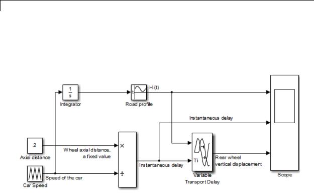
Variable Time Delay, Variable Transport Delay
The sldemo_VariableTransportDelay model shows how to model vertical wheel displacement on a one-dimensional car. The Variable Transport Delay block models the delay in vertical displacement of the rear wheel when the road profile changes:
2-2006
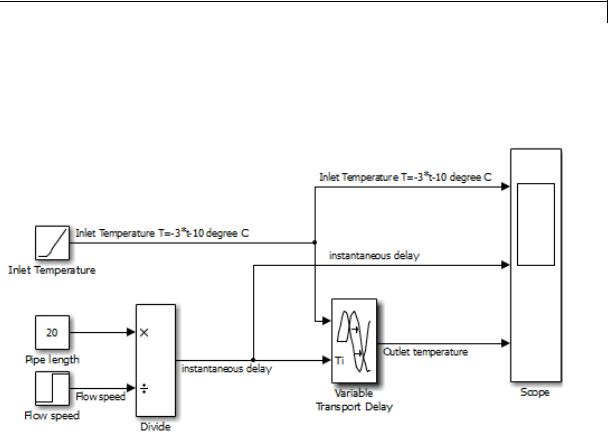
Variable Time Delay, Variable Transport Delay
The sldemo_VariableTransportDelay_pipe model shows how to model incompressible flow through a fixed-length pipe. The Variable Transport Delay block models the delay in temperature change at the outlet when fluid flow occurs:
Characteristics |
|
Direct Feedthrough |
Yes, of the time delay (second) input |
|
|
Sample Time |
Continuous |
|
|
Scalar Expansion |
Yes, of input and all parameters except |
|
|
|
Initial buffer size |
|
|
Dimensionalized |
Yes |
|
|
Zero-Crossing Detection |
No |
See Also |
|
Transport Delay |
|
2-2007

Variant Subsystem
Purpose |
Represent a subsystem with multiple subsystems |
Library |
Ports & Subsystems |
Description |
|
Data Type
Support
Variant subsystems provide multiple implementations for a subsystem where only one implementation is active during simulation. You can programmatically swap out the active implementation and with another implementation without modifying the model.
The Variant Subsystem block includes multiple child subsystems, where only one subsystem runs during simulation. The Variant Subsystem block also can include Inport, Outport, and Connection Port blocks. There are no drawn connections inside the Variant Subsystem block. Each child subsystem is associated with a variant object, which is created in the base workspace. The variant object is defined with a condition to determine if it is the active subsystem.
For information on the data types accepted by a subsystem’s input ports, see Inport block. For information on the data types output by a subsystem’s output ports, see Outport block.
For more information, see “Data Types Supported by Simulink” in the Simulink documentation.
2-2008
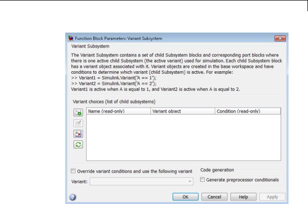
Variant Subsystem
Parameters and Dialog Box
•“Variant choices (list of child subsystems)” on page 2-2010
•“Name (read-only)” on page 2-2012
•“Variant object” on page 2-2013
•“Condition (read-only)” on page 2-2014
•“Override variant conditions and use following variant” on page 2-2015
•“Variant” on page 2-2016
•“Generate preprocessor conditionals” on page 2-2017
2-2009

Variant Subsystem
Variant choices (list of child subsystems)
Displays a table of subsystems, variant objects, and conditions, which are Boolean expressions that determine the active variant.
Settings
Default: The table has a row for each subsystem in the Variant Subsystem block. If the Variant Subsystem block does not contain any subsystems, then the table is empty. See each column parameter for its default value:
•“Name (read-only)” on page 2-2012
•“Variant object” on page 2-2013
•“Condition (read-only)” on page 2-2014
Tip
You can use buttons to the left of the Variant choices table to modify the elements of the table.
...To |
...Click |
|
|
Create and add a new subsystem choice: Places a new subsystem choice in the table and creates
a new subsystem block in the Variant Subsystem block diagram.
Create/Edit selected variant object: Creates a Simulink.Variant object in the base workspace and opens the Simulink.Variant object parameter dialog box to specify the variant Condition.
2-2010
Variant Subsystem
...To |
...Click |
|
|
Open selected subsystem variant choice: Opens the subsystem block diagram for the selected row in the Variant choices table.
Refresh dialog information from variant subsystem contents: Updates the Variant choices table according to the Subsystem block configuration and values of the variant object in the base workspace.
See Also
•“Configuring the Variant Subsystem Block”
•“Set Up Variant Subsystems”
•“Variant Systems”
2-2011

Variant Subsystem
Name (read-only)
Name of the subsystem (a subsystem contained in the Variant Subsystem block)
Settings
A read only field, based on the subsystems contained in the Variant Subsystem block diagram. To add a new subsystem to the Variant Subsystem block diagram, click the Create and add a new subsystem
choice button  .
.
2-2012
Variant Subsystem
Variant object
Display the Simulink.Variant objects in the base workspace or enter a variant object name in a new row.
Settings
Default: Variant
To enter a variant object name, double-click a Variant object cell in a new row and type in the variant object name. Define that variant object in the base workspace.
Command-Line Information
Structure field: Represented by the variant.Name field in the Variant parameter structure
Type: string
Value: Name of the Simulink.Variant object that represents the variant to which this element applies.
Default: ''
See Also
•“About Variant Objects”
•Simulink.Variant
2-2013

Variant Subsystem
Condition (read-only)
Displays the Condition for the Simulink.Variant object.
Settings
A read-only field, based on the condition for the associated variant object in the base workspace. Create or change a variant condition in the Simulink.Variant parameter dialog box or in the base workspace.
See Also
•“Variant Condition”
•Simulink.Variant
2-2014

Variant Subsystem
Override variant conditions and use following variant
Specify whether to designate the active variant from the evaluation of the variant conditions or from the value of the Variant parameter.
Settings
Default: Off
 On
On
Override the variant conditions and set the active variant to the value of the Variant parameter
 Off
Off
Determine the active variant by the value of the variant conditions
Dependencies
This parameter enables Variant.
Command-Line Information
Parameter: OverrideUsingVariant
Type: string
Value: '' if no overriding variant object is specified, or the name of the overriding variant object
Default: ''
See Also
•“Overriding Variant Conditions”
•“Select the Active Variant”
2-2015