

- •Block Reference
- •Commonly Used
- •Continuous
- •Discontinuities
- •Discrete
- •Logic and Bit Operations
- •Lookup Tables
- •Math Operations
- •Model Verification
- •Model-Wide Utilities
- •Ports & Subsystems
- •Signal Attributes
- •Signal Routing
- •Sinks
- •Sources
- •User-Defined Functions
- •Additional Math & Discrete
- •Additional Discrete
- •Additional Math: Increment — Decrement
- •Run on Target Hardware
- •Target for Use with Arduino Hardware
- •Target for Use with BeagleBoard Hardware
- •Target for Use with LEGO MINDSTORMS NXT Hardware
- •Blocks — Alphabetical List
- •Command-Line Information
- •Command-Line Information
- •Command-Line Information
- •Command-Line Information
- •Command-Line Information
- •Command-Line Information
- •Command-Line Information
- •Command-Line Information
- •Command-Line Information
- •Command-Line Information
- •Command-Line Information
- •Command-Line Information
- •Command-Line Information
- •Command-Line Information
- •Command-Line Information
- •Command-Line Information
- •Settings Pane
- •Measurements Pane
- •Signal Statistics Measurements
- •Settings Pane
- •Transitions Pane
- •Overshoots/Undershoots
- •Cycles
- •Settings Pane
- •Peaks Pane
- •Command-Line Information
- •Command-Line Information
- •Command-Line Information
- •Command-Line Information
- •Command-Line Information
- •Command-Line Information
- •Command-Line Information
- •Command-Line Information
- •Command-Line Information
- •Function Reference
- •Model Construction
- •Simulation
- •Linearization and Trimming
- •Data Type
- •Examples
- •Main Toolbar
- •Command-Line Alternative
- •Command-Line Alternative
- •Command-Line Alternative
- •Command-Line Alternative
- •Command-Line Alternative
- •Command-Line Alternative
- •Mask Icon Drawing Commands
- •Simulink Classes
- •Model Parameters
- •About Model Parameters
- •Examples of Setting Model Parameters
- •Common Block Parameters
- •About Common Block Parameters
- •Examples of Setting Block Parameters
- •Block-Specific Parameters
- •Mask Parameters
- •About Mask Parameters
- •Notes on Mask Parameter Storage
- •Simulink Identifier
- •Simulink Identifier
- •Model Advisor Checks
- •Simulink Checks
- •Simulink Check Overview
- •See Also
- •Identify unconnected lines, input ports, and output ports
- •Description
- •Results and Recommended Actions
- •Capabilities and Limitations
- •Tips
- •See Also
- •Check root model Inport block specifications
- •Description
- •Results and Recommended Actions
- •See Also
- •Check optimization settings
- •Description
- •Results and Recommended Actions
- •Tips
- •See Also
- •Description
- •Results and Recommended Actions
- •See Also
- •Check for implicit signal resolution
- •Description
- •Results and Recommended Actions
- •See Also
- •Check for optimal bus virtuality
- •Description
- •Results and Recommended Actions
- •Capabilities and Limitations
- •See Also
- •Description
- •Results and Recommended Actions
- •Capabilities and Limitations
- •See Also
- •Identify disabled library links
- •Description
- •Results and Recommended Actions
- •Capabilities and Limitations
- •Tips
- •See Also
- •Identify parameterized library links
- •Description
- •Results and Recommended Actions
- •Capabilities and Limitations
- •Tips
- •See Also
- •Identify unresolved library links
- •Description
- •Results and Recommended Actions
- •Capabilities and Limitations
- •See Also
- •Results and Recommended Actions
- •Capabilities and Limitations
- •See Also
- •Results and Recommended Actions
- •Capabilities and Limitations
- •See Also
- •Check usage of function-call connections
- •Description
- •Results and Recommended Actions
- •See Also
- •Check signal logging save format
- •Description
- •Results and Recommended Actions
- •See Also
- •Description
- •Results and Recommended Actions
- •See Also
- •Description
- •Results and Recommended Actions
- •Tips
- •See Also
- •Check data store block sample times for modeling errors
- •Description
- •Results and Recommended Actions
- •See Also
- •Check for potential ordering issues involving data store access
- •Description
- •Results and Recommended Actions
- •Tips
- •See Also
- •Check for partial structure parameter usage with bus signals
- •Description
- •Results and Recommended Actions
- •Tips
- •See Also
- •Check for calls to slDataTypeAndScale
- •Description
- •Results and Recommended Actions
- •Tips
- •See Also
- •Check for proper bus usage
- •Description
- •Results and Recommended Actions
- •Action Results
- •Tips
- •See Also
- •Description
- •Results and Recommended Actions
- •See Also
- •Description
- •Results and Recommended Actions
- •See Also
- •Check for proper Merge block usage
- •Description
- •Input Parameters
- •Results and Recommended Actions
- •See Also
- •Description
- •Results and Recommended Actions
- •Action Results
- •See Also
- •Check for non-continuous signals driving derivative ports
- •Description
- •Results and Recommended Actions
- •See Also
- •Runtime diagnostics for S-functions
- •Description
- •Results and Recommended Actions
- •See Also
- •Check file for foreign characters
- •Description
- •Results and Recommended Actions
- •Tips
- •See Also
- •Check model for known block upgrade issues
- •Description
- •Results and Recommended Actions
- •Action Results
- •See Also
- •Description
- •Results and Recommended Actions
- •Action Results
- •See Also
- •Check that the model is saved in SLX format
- •Description
- •Results and Recommended Actions
- •Tips
- •See Also
- •Check Model History properties
- •Description
- •Results and Recommended Actions
- •See Also
- •Analyze model hierarchy for upgrade issues
- •Description
- •Results and Recommended Actions
- •Tips
- •See Also
- •Description
- •Results and Recommended Actions
- •See Also
- •Simulink Performance Advisor Checks
- •Simulink Performance Advisor Check Overview
- •See Also
- •Baseline
- •See Also
- •Check Preupdate Items
- •See Also
- •Checks that need Update Diagram
- •See Also
- •Checks that require simulation to run
- •See Also
- •Check Accelerator Settings
- •See Also
- •Create Baseline
- •See Also
- •Identify resource intensive diagnostic settings
- •See Also
- •Check optimization settings
- •See Also
- •Identify inefficient lookup table blocks
- •See Also
- •Identify Interpreted MATLAB Function blocks
- •See Also
- •Check MATLAB Function block debug settings
- •See Also
- •Check Stateflow block debug settings
- •See Also
- •Identify simulation target settings
- •See Also
- •Check model reference rebuild setting
- •See Also
- •Check Model Reference parallel build
- •See Also
- •Check solver type selection
- •See Also
- •Select normal or accelerator simulation mode
- •See Also
- •Simulink Limits
- •Maximum Size Limits of Simulink Models
- •Index
- •Filter Structures and Filter Coefficients
- •Valid Initial States
- •Number of Delay Elements (Filter States)
- •Frame-Based Processing
- •Sample-Based Processing
- •Valid Initial States
- •Frame-Based Processing
- •Sample-Based Processing
- •Model Parameters in Alphabetical Order
- •Common Block Parameters
- •Continuous Library Block Parameters
- •Discontinuities Library Block Parameters
- •Discrete Library Block Parameters
- •Logic and Bit Operations Library Block Parameters
- •Lookup Tables Block Parameters
- •Math Operations Library Block Parameters
- •Model Verification Library Block Parameters
- •Model-Wide Utilities Library Block Parameters
- •Ports & Subsystems Library Block Parameters
- •Signal Attributes Library Block Parameters
- •Signal Routing Library Block Parameters
- •Sinks Library Block Parameters
- •Sources Library Block Parameters
- •User-Defined Functions Library Block Parameters
- •Additional Discrete Block Library Parameters
- •Additional Math: Increment - Decrement Block Parameters
- •Mask Parameters

fxptdlg
Show details for selected result
Display details for object selected in the Contents pane
Action
Use this option to:
•Determine why a fraction length cannot be proposed, for example, fraction lengths cannot be proposed for Library Links or Mask Subsystems.
•Provide access to showing blocks with shared data types.
•Obtain more information on the proposal for the selected result.
Command-Line Alternative
No command line alternative available.
4-183

fxptdlg
Shortcut Shortcut Editor Overview
Editor Use the Shortcut Editor to add or edit user-defined shortcuts. You cannot modify the factory default shortcuts. If you add a new shortcut and want it to appear as a button on the Fixed-Point Tool Shortcuts to set up runs pane, use the controls in the Manage shortcuts panel.
Name of shortcut
Enter a unique name for your shortcut. By default, the Fixed-Point Tool uses this name as the Run name for this shortcut.
If the shortcut name already exists, the new settings overwrite the existing settings.
4-184
fxptdlg
Allow modification of fixed-point instrumentation settings
Select whether to change the model fixed-point instrumentation settings when you apply this shortcut to the model.
Settings
Default: On
 On
On
When you apply this shortcut to the model, changes the fixed-point instrumentation settings of the model and its subsystems to the setting defined in this shortcut.
 Off
Off
Does not change the fixed-point instrumentation settings when you apply this shortcut to the model.
Tip
If you want to control data type override settings without altering the fixed-point instrumentation settings on your model, clear this option.
4-185

fxptdlg
Allow modification of data type override settings
Select whether to change the model data type override settings when you apply this shortcut to the model
Settings
Default: On
 On
On
When you apply this shortcut to the model, changes the data type override settings of the model and its subsystems to the settings defined in this shortcut .
 Off
Off
Does not change the fixed-point instrumentation settings when you apply this shortcut to the model.
4-186

fxptdlg
Allow modification of run name
Select whether to change the run name on the model when you apply this shortcut to the model
Settings
Default: On
 On
On
Changes the run name to the setting defined in this shortcut when you apply this shortcut to the model.
 Off
Off
Does not change the run name when you apply this shortcut to the model.
4-187

fxptdlg
Run name
Specify the run name to use when you apply this shortcut.
By default, the run name defaults to the name of the shortcut. Run names are case sensitive.
Dependency
Allow modification of run name enables this parameter.
4-188

fxptdlg
Capture system settings
Copy the model and subsystem fixed-point instrumentation mode and data type override settings into the Shortcut Editor.
4-189

fxptdlg
Fixed-point instrumentation mode
Control which objects in the shortcut editor log minimum, maximum and overflow data during simulation.
This information is stored in the shortcut. To use the current model setting, click Capture system settings.
Settings
Default: Same as model setting
Use local settings
Logs data according to the value of this parameter set for each subsystem. Otherwise, settings for parent systems always override those of child systems.
Minimums, maximums and overflows
Logs minimum value, maximum value, and overflow data for all blocks in the current system or subsystem during simulation.
Overflows only
Logs only overflow data for all blocks in the current system or subsystem.
Force off
Does not log data for any block in the current system or subsystem. Use this selection to work with models containing fixed-point enabled blocks if you do not have a Simulink Fixed Point license.
Dependency
Allow modification of fixed-point instrumentation settings enables this parameter.
4-190

fxptdlg
Data type override
Control data type override of objects that allow you to specify data types in their dialog boxes.
This information is stored in the shortcut. To use the current model settings, click Capture system settings.
Settings
Default: Same as model
The value of this parameter for parent systems controls data type override for all child subsystems, unless Use local settings is selected.
Use local settings
Overrides data types according to the setting of this parameter for each subsystem.
Scaled double
Overrides the data type of all blocks in the current system and subsystem with doubles; however, the scaling and bias specified in the dialog box of each block is maintained.
Double
Overrides the output data type of all blocks in the current system or subsystem with doubles. The overridden values have no scaling or bias.
Single
Overrides the output data type of all blocks in the current system or subsystem with singles. The overridden values have no scaling or bias.
Off
No data type override is performed on any block in the current system or subsystem. The settings on the blocks are used.
Dependency
Allow modification of data type override settings enables this parameter.
4-191

fxptdlg
See Also
“Data type override” on page 4-161
4-192

fxptdlg
Plot
Interface
Data type override applies to
Specifies which data types to override when you apply this shortcut.
This information is stored in the shortcut. To use the current model setting, click Capture system settings.
Settings
Default: All numeric types
All numeric types
Data type override applies to all numeric types, floating-point and fixed-point. It does not apply to boolean or enumerated data types.
Floating-point
Data type override applies only to floating-point data types, that is, double and single.
Fixed-point
Data type override applies only to fixed-point data types, for example, uint8, fixdt.
Dependency
Allow modification of data type override settings enables this parameter.
See Also
“Data type override applies to” on page 4-164
Manage shortcuts
Control which shortcuts appear as buttons on the Fixed-Point Tool Shortcuts to set up runs panel and the order in which they appear.
The Fixed-Point Tool uses the Simulation Data Inspector tool plotting capabilities that enable you to plot signals for graphical analysis. The tool can access signal data that resides in the MATLAB workspace, allowing you to plot simulation results associated with:
• Scope blocks whose Save data to workspace parameter is selected
4-193

fxptdlg
•To Workspace blocks
•Root-level Outport blocks, when the Output check box on the Data Import/Export pane of the Configuration Parameters dialog box is selected
•Logged signal data
Tip The Contents pane of the Fixed-Point Tool displays an antenna icon  next to items that you can plot.
Using the Simulation Data Inspector tool, you can:
•Compare signals
•Inspect signals
•Compare runs
Compare Signals
To compare signals:
1In one of the runs that you want to compare, select a logged signal.
2From the Fixed-Point Tool menu, select Results > Compare Signals or click  .
.
3If there are more than two runs, in the Compare Runs Selector dialog box, select the run that you want to compare, and then click
OK.
Plots the signal in both selected runs on the upper axes, and plots the difference between the selected runs on the lower axes. For more details, see “Propose Fraction Lengths Using Simulation Range Data”.
4-194
fxptdlg
Inspect Signal
To inspect a signal:
1Select the logged signal that you want to inspect.
2From the Fixed-Point Tool menu, select Results > Inspect Signal or click  .
.
Plots data as a function of time.
4-195

fxptdlg
Note that, unlike the Fixed-Point Tool, the Simulation Data Inspector allows multiple runs with the same name.
Compare Runs
To compare runs:
1In one of the runs that you want to compare, select a logged signal.
2From the Fixed-Point Tool menu, select Results > Compare Runs or click  .
.
3If there are more than two runs, in the Compare Runs Selector dialog box, select the run that you want to compare, and then click
OK.
4-196

fxptdlg
Plots the signal in both selected runs on the upper axes, and plots the difference between the selected runs on the lower axes.
Histogram Plot
To view the histogram plot of a signal:
1Select the logged signal that you want to plot.
2From the Fixed-Point Tool menu, select Results > Histogram Plot of Signal or click  .
.
The histogram plot helps you visualize the dynamic range of a signal. This plot provides information about the:
•Total number of samples (N)
•The maximum number of bits needed to prevent overflow
4-197

fxptdlg
Signal
Logging
Options
•Number of times each bit has been used to represent the data (as a percentage of the total number of samples)
•Number of times that exact zero occurred (without the effect of quantization). This does not include the number of zeroes that occurred due to rounding.
You can use this information to estimate the word size needed to represent the signal.
The Fixed-Point Tool provides options that allow you to control signal logging in a model (see “Signal Logging” inSimulink User’s Guide). Using these options, you can enable or disable logging for multiple signals simultaneously, based on signal attributes such as:
• The location of signals in a model hierarchy
4-198

fxptdlg
• Whether or not signals have names
The Fixed-Point Tool does not control signal logging for referenced models or subsystems with library links. It ignores these objects when enabling or disabling signal logging in a model hierarchy.
You can control the signal logging of a Simulink subsystem, that is placed inside of a Stateflow Chart, from the subsystem parent node.
How to Access the Signal Logging Options in the Fixed-Point Tool
1In the Model Hierarchy pane, right-click a node that represents either a model or a subsystem.
The Fixed-Point Tool displays a context menu for the selected node.
2In the context menu, select either Enable Signal Logging or
Disable Signal Logging.
The Fixed-Point Tool displays a submenu that lists a variety of signal logging options.
Signal Logging Options
Choose from the following signal logging options:
|
Select... |
To Enable or Disable Signal Logging |
|
|
|
for... |
|
|
All Signals in this |
All signals in the selected system |
|
|
System |
|
|
|
All Signals from Here |
All signals in the selected system and its |
|
|
Down |
subsystems |
|
|
Outports in this System |
All Outport blocks in the selected system |
|
|
Named Signals in this |
All signals in the selected system, whose |
|
|
System |
Signal name parameter specifies a |
|
|
|
value |
|
4-199

fxptdlg
Examples
See Also
|
Select... |
To Enable or Disable Signal Logging |
|
|
|
for... |
|
|
Named Signals from |
All signals in the selected system and |
|
|
Here Down |
its subsystems, whose Signal name |
|
|
|
parameter specifies a value |
|
|
Unnamed Signals in |
All signals in the selected system, whose |
|
|
this System |
Signal name parameter is empty |
|
|
Unnamed Signals from |
All signals in the selected system and |
|
|
Here Down |
its subsystems, whose Signal name |
|
|
|
parameter is empty |
|
To learn how to use the tool, see “Propose Fraction Lengths Using Simulation Range Data”.
autofixexp
4-200

gcb
Purpose |
Get pathname of current block |
Syntax |
gcb |
|
gcb('sys') |
Description |
gcb returns the full block pathname of the current block in the current |
|
system. |
|
gcb('sys') returns the full block pathname of the current block in |
|
the specified system. |
|
The current block is one of these: |
|
• During editing, the current block is the block most recently clicked. |
|
• During simulation of a system that contains S-Function blocks, |
|
the current block is the S-Function block currently executing its |
|
corresponding MATLAB function. |
|
• During callbacks, the current block is the block whose callback |
|
routine is being executed. |
|
• During evaluation of the MaskInitialization string, the current |
|
block is the block whose mask is being evaluated. |
Examples |
This command returns the path of the most recently selected block. |
|
gcb |
|
ans = |
|
clutch/Locked/Inertia |
|
This command gets the value of the Gain parameter of the current block. |
|
get_param(gcb,'Gain') |
|
ans = |
|
1/(Iv+Ie) |
See Also |
gcbh | gcs |
4-201

gcbh
Purpose |
Get handle of current block |
Syntax |
gcbh |
Description |
gcbh returns the handle of the current block in the current system. |
|
You can use this command to identify or address blocks that have no |
|
parent system. The command should be most useful to blockset authors. |
Examples
See Also
This command returns the handle of the most recently selected block.
gcbh
ans =
281.0001
gcb
4-202

gcs
Purpose |
Get pathname of current system |
Syntax |
gcs |
Description |
gcs returns the full pathname of the current system. |
|
The current system is one of these: |
|
• During editing, the current system is the system or subsystem most |
|
recently clicked. |
|
• During simulation of a system that contains S-Function blocks, the |
|
current system is the system or subsystem containing the S-Function |
|
block that is currently being evaluated. |
|
• During callbacks, the current system is the system containing any |
|
block whose callback routine is being executed. |
|
• During evaluation of the MaskInitialization string, the current |
|
system is the system containing the block whose mask is being |
|
evaluated. |
|
The current system is always the current model or a subsystem of the |
|
current model. Use bdroot to get the current model. |
Examples |
This example returns the path of the system that contains the most |
|
recently selected block. |
|
gcs |
|
ans = |
|
clutch/Locked |
See Also |
bdroot | gcb |
4-203

get_param
Purpose
Syntax
Description
Input
Arguments
Get system and block parameter values
paramValue = get_param(object, paramName) paramValues = get_param(objectCellArray, paramName) paramValue = get_param(objectHandle, paramName) paramValue = get_param(0, paramName)
paramStruct = get_param(object, 'ObjectParameters') paramCellArray = get_param(object, 'DialogParameters')
paramValue = get_param(object, paramName) returns the value of the specified parameter. Some parameters are case-sensitive, and some are not. To prevent problems, treat all parameters as case-sensitive.
paramValues = get_param(objectCellArray, paramName) accepts a cell array of full path specifiers, enabling you to get the values of a parameter common to all objects specified in the cell array.
paramValue = get_param(objectHandle, paramName) returns the value of the specified parameter of the object whose handle is objectHandle.
paramValue = get_param(0, paramName) returns the current value of a Simulink session parameter or the default value of a model or block parameter.
paramStruct = get_param(object, 'ObjectParameters') returns a structure that describes object’s parameters.
paramCellArray = get_param(object, 'DialogParameters') returns a cell array containing the names of object’s dialog parameters.
object
A model object for which get_param is to return a specified parameter value.
objectCellArray
A cell array of full path specifiers of objects for which get_param is to return the values of a specified parameter.
4-204
get_param
Output
Arguments
Examples
objectHandle
A handle to a model object for which get_param is to return a specified parameter value.
paramName
The name of a parameter for which get_param is to return a value or values.
paramCellArray
A cell array containing the names of the dialog parameters of object.
paramStruct
A structure containing information about the parameters of object. Each field of the structure corresponds to the parameter with the same name as the field. Each field contains three subordinate fields: Type, Enum (if applicable), and Attributes. These fields respectively specify the parameter’s data type, enumerated values (if applicable) , and attributes.
paramValue
The value of the parameter specified by paramName.
paramValues
A list containing the value of the parameter specified by paramName in each object specified in objectCellArray.
Return the value of the Gain parameter for the Inertia block in the
Requisite Friction subsystem of the clutch system:
get_param('sldemo_clutch/Friction Mode Logic/Requisite Friction/Inert ans =
1/(Iv+Ie)
4-205

get_param
Display the block types of all blocks in the current system:
blks = find_system(gcs, 'Type', 'block'); listblks = get_param(blks, 'BlockType')
listblks =
'SubSystem'
'Inport'
'Constant'
'Gain'
'Sum'
'Outport'
Return the name of the currently selected block:
get_param(gcb, 'Name')
Get the attributes of the currently selected block’s Name parameter:
p = get_param(gcb, 'ObjectParameters'); a = p.Name.Attributes
ans =
'read-write' 'always-save'
Get the dialog parameters of a Sine Wave block:
p = get_param('untitled/Sine Wave', 'DialogParameters') p =
SineType: [1x1 struct] TimeSource: [1x1 struct] Amplitude: [1x1 struct]
4-206

get_param
Bias: [1x1 struct]
Frequency: [1x1 struct]
Phase: [1x1 struct]
Samples: [1x1 struct]
Offset: [1x1 struct]
SampleTime: [1x1 struct]
VectorParams1D: [1x1 struct]
See Also |
find_system | gcb | set_param |
|
How To |
• |
“Associating User Data with Blocks” |
|
• |
“Model Parameters” on page 8-2 |
|
• |
“Block-Specific Parameters” on page 8-109 |
|
• “Common Block Parameters” on page 8-96 |
|
|
• “Use MATLAB Commands to Change Workspace Data” |
|
4-207

getActiveConfigSet
Purpose
Syntax
Arguments
Description
Examples
See Also
How To
Get model’s active configuration set or configuration reference
myConfigObj = getActiveConfigSet('model')
model
The name of an open model, or gcs to specify the current model
getActiveConfigSet returns the configuration set or configuration reference (configuration object) that is the active configuration object of 'model'.
The following example returns the active configuration object of the current model. The code is the same whether the object is a configuration set or configuration reference.
myConfigObj = getActiveConfigSet(gcs);
attachConfigSet | attachConfigSetCopy | closeDialog | detachConfigSet | getConfigSet | getConfigSets | openDialog | setActiveConfigSet
•“Manage a Configuration Set”
•“Manage a Configuration Reference”
4-208

getCallbackAnnotation
Purpose |
Get information about annotation |
Syntax getCallbackAnnotation
Description getCallbackAnnotation is intended to be invoked by annotation callback functions. If it is invoked from an annotation callback function, it returns an instance of Simulink.Annotation class that represents the annotation associated with the callback function. The callback function can then use the instance to get and set the annotation’s properties, such as its text, font and color. If this function is not invoked from an annotation callback function, it returns nothing, i.e., [].
4-209

getConfigSet
Purpose
Syntax
Arguments
Description
Examples
See Also
How To
Get one of model’s configuration sets or configuration references
myConfigObj = getConfigSet('model', 'configObjName')
model
The name of an open model, or gcs to specify the current model
configObjName
The name of a configuration set (Simulink.ConfigSet) or configuration reference (Simulink.ConfigSetRef)
getConfigSet returns the configuration set or configuration reference (configuration object) that is attached to model and is named configObjName. If no such object exists, an error occurs.
The following example returns the configuration object that is named DevConfig and attached to the current model. The code is the same whether DevConfig is a configuration set or configuration reference.
myConfigObj = getConfigSet(gcs, 'DevConfig');
attachConfigSet | attachConfigSetCopy | closeDialog | detachConfigSet | getActiveConfigSet | getConfigSets | openDialog | setActiveConfigSet
•“Manage a Configuration Set”
•“Manage a Configuration Reference”
4-210

getConfigSets
Purpose
Syntax
Arguments
Description
Examples
See Also
How To
Get names of all of model’s configuration sets or configuration references
myConfigObjNames = getConfigSets('model')
model
The name of an open model, or gcs to specify the current model
getConfigSets returns a cell array of strings specifying the names of all configuration sets and configuration references (configuration objects) attached to 'model'.
The following example obtains the names of the configuration objects attached to the current model.
myConfigObjNames = getConfigSets(gcs)
attachConfigSet | attachConfigSetCopy | closeDialog | detachConfigSet | getActiveConfigSet | getConfigSet | openDialog | setActiveConfigSet
•“Manage a Configuration Set”
•“Manage a Configuration Reference”
4-211

getfullname
Purpose |
Get pathname of block or line |
Syntax |
path=getfullname(handle) |
Description |
path=getfullname(handle) returns the full pathname of the block or |
|
line specified by handle. |
Examples |
getfullname(gcb) returns the pathname of the block currently selected |
|
in the model editor’s window. |
|
The following code returns the pathname of the line currently selected |
|
in the model editor’s window. |
|
line = find_system(gcs, 'SearchDepth', 1, 'FindAll', 'on', ... |
|
'Type', 'line', 'Selected', 'on'); |
|
path = getfullname(line); |
See Also |
gcb | find_system |
4-212

getRootInportMap
Purpose |
Creates custom object to map signals to root-level inports |
Syntax |
map = getRootInportMap('empty'); |
|
map = getRootInportMap('model','mdl',Name, Value); |
|
map = getRootInportMap('model','mdl', 'Name', {Value1, |
|
Value2}); |
Description |
map = getRootInportMap('empty'); creates an empty map object, |
|
map. Use this map object to set up an empty custom mapping object. |
|
map = getRootInportMap('model','mdl',Name, Value); creates |
|
a map object for model, mdl, with block names and signal names |
|
specified, one block or signal name per pair. |
|
map = getRootInportMap('model','mdl', 'Name', {Value1, |
|
Value2}); creates a map object for model, mdl, with block names |
|
signals specified in a cell array. |
|
Use the getRootInportMap function when creating a custom mapping |
|
mode to map data to root-level inports. See BlockNameIgnorePrefix.m |
|
for an example of a custom mapping algorithm. |
Tips |
Load the model before running this function. |
Input |
empty |
Arguments |
Create an empty map object. |
|
|
|
Default: none |
|
Name-Value Pair Arguments |
|
Specify optional comma-separated pairs of Name,Value arguments, |
|
where Name is the argument name and Value is the corresponding |
|
value. Name must appear inside single quotes (' '). You can |
|
specify several name and value pair arguments in any order as |
|
Name1,Value1,...,NameN,ValueN. |
|
blockName |
4-213

getRootInportMap
Block names of root-level input ports. The tool assigns data to ports according to the name of the root-inport block. If the tool finds a data element whose name matches the name of a root-inport block, it maps the data to the corresponding port.
The value for this argument can be:
Block name of root-level input ports.
Cell array containing multiple block names of root-level input ports.
Default: None
|
signalName |
|
Signal names to be mapped. The tool assigns data to ports according |
|
to the name of the signal on the port. If the tool finds a data element |
|
whose name matches the name of a signal at a port, it maps the data |
|
to the corresponding port. |
|
The value for this argument can be: |
|
Signal name to be mapped. |
|
Cell array containing multiple signal names of signals to be mapped. |
|
Default: None |
Output |
map |
Arguments |
Custom object that you can use to map data to root-level input port. |
|
|
Examples |
Empty Mapping Object |
|
Create an empty custom mapping object. |
|
map = getRootInportMap('empty') |
|
map = |
|
1x0 empty Simulink.iospecification.InputMap |
|
Package: Simulink.iospecification |
4-214
getRootInportMap
Properties:
Type
DataSourceName
Destination
Simple Mapping Object
Create a simple mapping object using a MATLAB time series object. Create a time series object, signalIn1.
signalIn1 = timeseries((1:10)');
Common Properties:
Name: 'unnamed'
Time: [10x1 double]
TimeInfo: [1x1 tsdata.timemetadata]
Data: [10x1 double]
DataInfo: [1x1 tsdata.datametadata]
Create a mapping object for the time series object for the model, matlabroot\help\toolbox\simulink\examples\ex_minportsOnlyModel.
map = getRootInportMap('model','ex_minportsOnlyModel',...
'blockName','In1','signalname','signalIn1')
map =
Simulink.iospecification.InputMap
Package: Simulink.iospecification
Properties:
Type: 'Inport'
DataSourceName: 'signalIn1'
Destination: [1x1 Simulink.iospecification.Destination]
4-215

getRootInportMap
Mapping Object with Vectors
Related
Examples
Create a mapping object using vectors of block names and signal names for the model
matlabroot\help\toolbox\simulink\examples\ex_minportsOnlyModel.
Create a mapping object of vectors.
map = getRootInportMap('model','ex_minportsOnlyModel',...
'blockName',{'In1' 'In2'}, ...
'signalname',{'signalIn1' 'signalIn2'});
• “Create Custom Mapping File Function”
4-216

getVariable
Purpose
Syntax
Description
Input
Arguments
Output
Arguments
Examples
See Also
Get value of variable from workspace
variableValue = getVariable(workspaceHandle,variableName) variableValue = workspaceHandle.getVariable(variableName)
variableValue = getVariable(workspaceHandle,variableName) returns the value of the variable. If the variable does not exist in the workspace, an error occurs.
variableValue = workspaceHandle.getVariable(variableName) is an alternative syntax.
workspaceHandle
Handle to the workspace containing the variable.
variableName
Name of the variable containing the value.
variableValue
Value of the variable.
Get the value of the workspace variable K, which is defined in model mdl.
wksp = get_param(mdl,'ModelWorkspace') value = wksp.getVariable('K')
value = 5
get_param
4-217

hasVariable
Purpose
Syntax
Description
Input
Arguments
Output
Arguments
Examples
See Also
Determine if variable exists in workspace
variableExists = hasVariable(workspaceHandle,variableName) variableExists = workspaceHandle.hasVariable(variableName)
variableExists = hasVariable(workspaceHandle,variableName) returns 1 if the variable exists in the workspace, and 0 if not.
variableExists = workspaceHandle.hasVariable(variableName) is an alternative syntax.
workspaceHandle
Handle to the workspace.
variableName
Name of the variable.
variableExists
Boolean value that indicates whether the variable exists in the workspace (1 if true and 0 if false).
Determine if the variable K exists in the workspace for model mdl.
wksp = get_param(mdl,`ModelWorkspace') exists = wksp.hasVariable('K')
exists = 1
get_param
4-218

hilite_system
Purpose
Syntax
Description
Highlight Simulink object
hilite_system(block_path) hilite_system(block_path, hilite_scheme)
hilite_system(block_path) highlights a model object using colors specified by the default highlighting scheme.
hilite_system(block_path, hilite_scheme) highlights a model object using the foreground and background colors specified in the highlighting scheme.
Tips |
• Calling hilite_system does not clear highlighted objects from |
|
previous hilite_system calls. |
|
• Using a traceability tag for block_path requires a Simulink Coder |
|
license. If you call hilite_system with a traceability tag as input, do |
|
the following: |
|
- If you closed and reopened a model, you must update the model |
|
before calling hilite_system. |
|
- If you changed your model, such as adding a block to your diagram, |
|
before calling hilite_system, generate new code for the model. |
|
When the system hierarchy of the model changes, traceability tags |
|
change. If you use a traceability tag from previously generated |
|
code, hilite_system might highlight the wrong block. |
|
- If a block name contains a newline character (\n), it is replaced |
|
with a space for readability. When calling hilite_system, in the |
|
block path string, replace the newline character with a space. |
|
• hilite_system might not work for a block, if the block name |
|
contains: |
|
- A single quote ('). |
|
- An asterisk (*), that causes a name-mangling ambiguity relative |
|
to other names in the model. This name-mangling ambiguity |
|
occurs in a block name or at the end of a block name if an asterisk |
|
precedes or follows a slash (/). |
4-219

hilite_system
Input
Arguments
Definitions
- The character (char(255)).
block_path
A string in two possible formats:
•A full block path
•A traceability tag from the comments of Simulink Coder generated code. Using a traceability tag requires a Simulink Coder license. In this case, the format is <system>/block_name:
-system is one of the following:
•The string Root.
•A unique system number assigned by the Simulink engine.
-block_name is the name of the source block. If a block name contains a newline character (\n), in the block path string, replace the newline character with a space.
hilite_scheme
String identifying a highlighting scheme name. For more information, see “Highlighting Scheme” on page 4-220.
Highlighting Scheme
A highlighting scheme specifies the foreground and background colors for a model object. Possible highlighting scheme names are:
default
none (clears the highlighting for an object) find
unique different user1 user2 user3 user4
4-220

hilite_system
user5
You can alter the specification for a highlighting scheme by using the following command:
set_param(0, 'HiliteAncestorsData', HILITE_DATA)
HILITE_DATA is a MATLAB structure array with the following fields:
•'HiliteType': string specifying a highlighting scheme.
•'ForegroundColor': string specifying a foreground “Color” on page 4-221.
•'BackgroundColor': string specifying a background “Color” on page 4-221.
Color
The supported color strings for foreground and background colors are:
black white gray red orange yellow green
darkGreen blue lightBlue cyan magenta
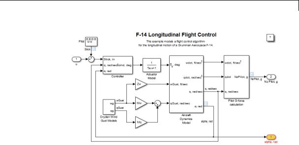
Examples Open the example model sldemo_f14, and use the block path to highlight the Controller block.
hilite_system('sldemo_f14/Controller')
4-221

hilite_system
In the model diagram, the Controller block is highlighted yellow.
If you have a Simulink Coder license, you can trace generated code to the corresponding source system or block in a model:
1Open the example model sldemo_f14. Open the Configuration Parameters dialog box, go to the Solver pane, and set solver parameters as follows:
•Set the solver Type to Fixed-step.
•Set Fixed step size to 0.1.
2Generate code for the sldemo_f14 model.
3In an editor or within an HTML code generation report, open a generated source or header file.
4As you review lines of code, note traceability tags that correspond to code of interest. To highlight a block using a traceability tag, enter:
hilite_system('<Root>/alpha, rad')
The following figure shows block alpha, rad highlighted.
4-222
hilite_system
You can also use the hilite_system command to highlight a block within a subsystem. Specify the Aircraft Dynamics Model subsystem using its traceability tag.
hilite_system('<S1>/Vertical Channel')
4-223

hilite_system
See Also |
rtwtrace |
4-224
intersect
Purpose |
Returns intersection of two vectors of Simulink.VariableUsage objects |
Syntax |
VarsOut = intersect (VarsIn1, VarsIn2) |
|
VarsOut = VarsIn1.intersect (VarsIn2) |
Description |
VarsOut = intersect (VarsIn1, VarsIn2) inputs two vectors of |
|
Simulink.VariableUsage objects and returns a vector containing a |
|
Simulink.VariableUsage object for each variable that is represented in |
|
both input vectors. The function compares input objects by comparing |
|
their Name, Workspace, and WorkspaceType values. If all three value |
|
are the same in both objects, the two objects match. Any returned object |
|
is a new object having the same field values as the matching input |
|
objects, except that its UsedByBlocks field contains the union of the |
|
values in the UsedByBlocks fields of the two matching objects. |
|
VarsOut = VarsIn1.intersect (VarsIn2) is the equivalent method |
|
syntax (Simulink.VariableUsage.intersect) and gives identical |
|
results. |
Input |
VarsIn1 |
Arguments |
A vector of Simulink.VariableUsage objects |
|
|
|
VarsIn2 |
|
Another vector of Simulink.VariableUsage objects |
Output |
VarsOut |
Arguments |
A vector of Simulink.VariableUsage objects containing a copy of any |
|
object in VarsIn1 that matches an object in VarsIn2. Two objects match |
|
if their Name, Workspace, and WorkspaceType values are the same. The |
|
UsedByBlocks field of each returned object is the union of the values of |
|
that field in the matching input objects. |
Examples |
Given two models, discover which variables are needed by the first |
|
model, the second model, or both models: |
4-225

intersect
|
model1Vars = Simulink.findVars('model1'); |
||
|
model2Vars |
= |
Simulink.findVars('model2'); |
|
commonVars |
= |
intersect(model1Vars, model2Vars); |
See Also |
Simulink.findVars | Simulink.VariableUsage | setdiff |
||
4-226

legacy_code
Purpose
Syntax
Description
Use Legacy Code Tool
legacy_code('help')
specs = legacy_code('initialize') legacy_code('sfcn_cmex_generate', specs) legacy_code('compile', specs, compilerOptions) legacy_code('generate_for_sim', specs, modelname) legacy_code('slblock_generate', specs, modelname) legacy_code('sfcn_tlc_generate', specs) legacy_code('rtwmakecfg_generate', specs) legacy_code('backward_compatibility')
The legacy_code function creates a MATLAB structure for registering the specification for existing C or C++ code and the S-function being generated. In addition, the function can generate, compile and link, and create a masked block for the specified S-function. Other options include generating
•A TLC file for simulation in Accelerator mode or code generation
•An rtwmakecfg.m file that you can customize to specify dependent source and header files that reside in a different directory than that of the generated S-function
legacy_code('help') displays instructions for using Legacy Code Tool.
specs = legacy_code('initialize') initializes the Legacy Code Tool data structure, specs, which registers characteristics of existing C or C++ code and properties of the S-function that the Legacy Code Tool generates.
legacy_code('sfcn_cmex_generate', specs) generates an S-function source file as specified by the Legacy Code Tool data structure, specs.
legacy_code('compile', specs, compilerOptions) compiles and links the S-function generated by the Legacy Code Tool based on the data structure, specs, and any compiler options that you might specify. The following examples show how to specify no options, one option, and multiple options:
4-227

legacy_code
legacy_code('compile', s);
legacy_code('compile', s, '-DCOMPILE_VALUE1=1');
legacy_code('compile', s,...
{'-DCOMPILE_VALUE1=1', '-DCOMPILE_VALUE2=2',...
'-DCOMPILE_VALUE3=3'});
legacy_code('generate_for_sim', specs, modelname) generates, compiles, and links the S-function in a single step. If the Options.useTlcWithAccel field of the Legacy Code Tool data structure is set to logical 1 (true), the function also generates a TLC file for accelerated simulations.
legacy_code('slblock_generate', specs, modelname) generates a masked S-Function block for the S-function generated by the Legacy Code Tool based on the data structure, specs. The block appears in the Simulink model specified by modelname. If you omit modelname, the block appears in an empty model editor window.
legacy_code('sfcn_tlc_generate', specs) generates a TLC file for the S-function generated by the Legacy Code Tool based on the data structure, specs. This option is relevant if you want to:
•Force Accelerator mode in Simulink software to use the TLC inlining code of the generated S-function. See the description of the ssSetOptions SimStruct function and
SS_OPTION_USE_TLC_WITH_ACCELERATOR S-function option for more information.
•Use Simulink Coder software to generate code from your Simulink model. For more information, see “Integrate External Code Using Legacy Code Tool”.
legacy_code('rtwmakecfg_generate', specs) generates an rtwmakecfg.m file for the S-function generated by the Legacy Code Tool based on the data structure, specs. This option is relevant only if you use Simulink Coder software to generate code from your Simulink model. For more information, see “Use rtwmakecfg.m API to Customize Generated Makefiles” and “Integrate External Code Using Legacy Code Tool” in the Simulink Coder documentation.
4-228

legacy_code
Input
Arguments
legacy_code('backward_compatibility') automatically updates syntax for using Legacy Code Tool, as made available from MATLAB Central in releases before R2006b, to the supported syntax described in this reference page and in “Integrate C Functions Using Legacy Code Tool”.
specs
A structure with the following fields:
Name the S-function
SFunctionName (Required) — A string specifying a name for the S-function to be generated by the Legacy Code Tool.
Define Legacy Code Tool Function Specifications
•InitializeConditionsFcnSpec — A nonempty string specifying a reentrant function that the S-function calls to initialize and reset states. You must declare this function by using tokens that Simulink software can interpret as explained in “Declaring Legacy Code Tool Function Specifications”.
•OutputFcnSpec — A nonempty string specifying the function that the S-function calls at each time step. You must declare this function by using tokens that Simulink software can interpret as explained in “Declaring Legacy Code Tool Function Specifications”.
•StartFcnSpec — A string specifying the function that the S-function calls when it begins execution. This function can access S-function parameter arguments only. You must declare this function by using tokens that Simulink software can interpret as explained in “Declaring Legacy Code Tool Function Specifications”.
•TerminateFcnSpec — A string specifying the function that the S-function calls when it terminates execution. This function can access S-function parameter arguments only. You must declare this function by using tokens that Simulink software
4-229

legacy_code
can interpret as explained in “Declaring Legacy Code Tool Function Specifications”.
Define Compilation Resources
•HeaderFiles — A cell array of strings specifying the file names of header files required for compilation.
•SourceFiles — A cell array of strings specifying source files required for compilation. You can specify the source files using absolute or relative path names.
•HostLibFiles — A cell array of strings specifying library files required for host compilation. You can specify the library files using absolute or relative path names.
•TargetLibFiles — A cell array of strings specifying library files required for target (that is, standalone) compilation. You can specify the library files using absolute or relative path names.
•IncPaths — A cell array of strings specifying directories containing header files. You can specify the directories using absolute or relative path names.
•SrcPaths — A cell array of strings specifying directories containing source files. You can specify the directories using absolute or relative path names.
•LibPaths — A cell array of strings specifying directories containing host and target library files. You can specify the directories using absolute or relative path names.
Specify a Sample Time
SampleTime — One of the following:
•'inherited' (default) — Sample time is inherited from the source block.
4-230

legacy_code
•'parameterized' — Sample time is represented as a tunable parameter. Generated code can access the parameter by calling MEX API functions, such as mxGetPr or mxGetData.
•Fixed — Sample time that you explicitly specify. For information on how to specify sample time, see “Specify Sample Time”.
If you specify this field, you must specify it last.
Define S-Function Options
Options — A structure that controls S-function options. The structure’s fields include:
•isMacro — A logical value specifying whether the legacy code is a C macro. By default, the value is false (0).
•isVolatile — A logical value specifying the setting of the S-function SS_OPTION_NONVOLATILE option. By default, the value is true (1).
•canBeCalledConditionally — A logical value specifying the setting of the S-function
SS_OPTION_CAN_BE_CALLED_CONDITIONALLY option. By default, the value is true (1).
•useTlcWithAccel — A logical value specifying the setting of the S-function SS_OPTION_USE_TLC_WITH_ACCELERATOR option. By default, the value is true (1).
•language — A string specifying either 'C' or 'C++' as the target language of the S-function that Legacy Code Tool will produce. By default, the value is 'C'.
Note The Legacy Code Tool can interface with C++ functions, but not C++ objects. For a work around, see “Legacy Code Tool Limitations” in the Simulink documentation.
4-231

legacy_code
•singleCPPMexFile — A logical value that, if true, specifies that generated code:
—Requires you to generate and manage an inlined S-function as only one file (.cpp) instead of two (.c and .tlc).
—Maintains model code style (level of parentheses usage and preservation of operand order in expressions and condition expressions in if statements) as specified by model configuration parameters.
By default, the value is false.
Limitations You cannot set the singleCPPMexFile field to true if
—Options.language='C++'
—You use one of the following Simulink objects with the IsAlias property set to true:
Simulink.Bus
Simulink.AliasType
Simulink.NumericType
—The Legacy Code Tool function specification includes a void* or void** to represent scalar work data for a state argument
—HeaderFiles field of the Legacy Code Tool structure specifies multiple header files
•supportsMultipleExecInstances— A logical value specifying whether to include a call to the
ssSupportsMultipleExecInstances function. By default, the value is false (0).
4-232

legacy_code
modelname
The name of a Simulink model into which Legacy Code Tool is to insert the masked S-function block generated when you specify legacy_code with the action string 'slblock_generate'. If you omit this argument, the block appears in an empty model editor window.
How To |
• |
“Integrate C Functions Using Legacy Code Tool” |
|
• |
“Integrate External Code Using Legacy Code Tool” |
4-233

libinfo
Purpose
Syntax
Description
Input
Arguments
Output
Arguments
See Also
Get information about library blocks referenced by model
libdata = libinfo('system')
libdata = libinfo('system', constraint1, value1, ...)
libdata = libinfo('system') returns information about library blocks referenced by system and all the systems underneath it.
libdata = libinfo('system', constraint1, value1, ...)
restricts the search as indicated by the search constraint(s) c1, v1, ...
system
The system to search recursively for library blocks.
constraint1, value1, ...
One or more pairs, each consisting of a search constraint followed by a constraint value. You can specify any of the search constraints that you can use with find_system.
libdata
An array of structures that describes each library block referenced by system. Each structure has the following fields:
Block |
Path of the link to the library |
|
block |
Library |
Name of the library containing |
|
the referenced block |
ReferenceBlock |
Path of the library block |
LinkStatus |
Value of the LinkStatus |
|
parameter for the link to the |
|
library block |
find_system |
|
4-234
libinfo
How To |
• “About Block Libraries and Linked Blocks” |
4-235

linmod
Purpose |
Extract continuous-time linear state-space model around operating |
|
point |
Syntax |
argout = linmod('sys'); |
|
argout = linmod('sys',x,u); |
|
argout = linmod('sys', x, u, para); |
|
argout = linmod('sys', x, u, 'v5'); |
|
argout = linmod('sys', x, u, para, 'v5'); |
|
argout = linmod('sys', x, u, para, xpert, upert, 'v5'); |
Arguments sys
x and u
Ts
Name of the Simulink system from which the linear model is extracted.
State (x) and the input (u) vectors. If specified, they set the operating point at which the linear model is extracted. When a model has model references using the Model block, you must use the Simulink structure format to specify x. To extract the x structure from the model, use the following command:
x = Simulink.BlockDiagram.getInitialState('sys');
You can then change the operating point values within this structure by editing x.signals.values.
If the state contains different data types (for example, 'double' and 'uint8'), then you cannot use a vector to specify this state. You must use
a structure instead. In addition, you can only specify the state as a vector if the state data type
is 'double'.
Sample time of the discrete-time linearized model
4-236

linmod
'v5' |
An optional argument that invokes the perturbation |
|
algorithm created prior to MATLAB 5.3. Invoking |
|
this optional argument is equivalent to calling |
|
linmodv5. |
para |
A three-element vector of optional arguments: |
|
• para(1) — Perturbation value of delta, the value |
|
used to perform the perturbation of the states |
|
and the inputs of the model. This is valid for |
|
linearizations using the 'v5' flag. The default |
|
value is 1e-05. |
|
• para(2) — Linearization time. For blocks that |
|
are functions of time, you can set this parameter |
|
with a nonnegative value that gives the time (t) |
|
at which Simulink evaluates the blocks when |
|
linearizing a model. The default value is 0. |
|
• para(3) — Set para(3)=1 to remove extra states |
|
associated with blocks that have no path from |
|
input to output. The default value is 0. |
xpert and |
The perturbation values used to perform the |
upert |
perturbation of all the states and inputs of the |
|
model. The default values are |
|
xpert = para(1) + 1e-3*para(1)*abs(x) |
|
upert = para(1) + 1e-3*para(1)*abs(u) |
|
When a model has model references using the Model |
|
block, you must use the Simulink structure format |
|
to specify xpert. To extract the xpert structure, use |
|
the following command: |
|
xpert = Simulink.BlockDiagram.getInitialState('sys'); |
4-237

linmod
Description
|
You can then change the perturbation values within |
|
this structure by editing xpert.signals.values. |
|
The perturbation input arguments are only available |
|
when invoking the perturbation algorithm created |
|
prior to MATLAB 5.3, either by calling linmodv5 or |
|
specifying the 'v5' input argument to linmod. |
argout |
linmod, dlinmod, and linmod2 return state-space |
|
representations if you specify the output (left-hand) |
|
side of the equation as follows: |
|
• [A,B,C,D] = linmod('sys', x, u) obtains the |
|
linearized model of sys around an operating |
|
point with the specified state variables x and the |
|
input u. If you omit x and u, the default values |
|
are zero. |
|
linmod and dlinmod both also return a |
|
transfer function and MATLAB data structure |
|
representations of the linearized system, depending |
|
on how you specify the output (left-hand) side of the |
|
equation. Using linmod as an example: |
|
• [num, den] = linmod('sys', x, u) returns |
|
the linearized model in transfer function form. |
|
• sys_struc = linmod('sys', x, u) returns a |
|
structure that contains the linearized model, |
|
including state names, input and output names, |
|
and information about the operating point. |
linmod compute a linear state-space model by linearizing each block in a model individually.
4-238

linmod
|
linmod obtains linear models from systems of ordinary differential |
|
equations described as Simulink models. Inputs and outputs are |
|
denoted in Simulink block diagrams using Inport and Outport blocks. |
|
The default algorithm uses preprogrammed analytic block Jacobians |
|
for most blocks which should result in more accurate linearization |
|
than numerical perturbation of block inputs and states. A list of |
|
blocks that have preprogrammed analytic Jacobians is available in the |
|
Simulink Control Design documentation along with a discussion of the |
|
block-by-block analytic algorithm for linearization. |
|
The default algorithm also allows for special treatment of problematic |
|
blocks such as the Transport Delay and the Quantizer. See the mask |
|
dialog of these blocks for more information and options. |
Notes |
By default, the system time is set to zero. For systems that are |
|
dependent on time, you can set the variable para to a two-element |
|
vector, where the second element is used to set the value of t at which |
|
to obtain the linear model. |
|
The ordering of the states from the nonlinear model to the linear model |
|
is maintained. For Simulink systems, a string variable that contains |
|
the block name associated with each state can be obtained using |
|
[sizes,x0,xstring] = sys |
|
where xstring is a vector of strings whose ith row is the block name |
|
associated with the ith state. Inputs and outputs are numbered |
|
sequentially on the diagram. |
|
For single-input multi-output systems, you can convert to transfer |
|
function form using the routine ss2tf or to zero-pole form using ss2zp. |
|
You can also convert the linearized models to LTI objects using ss. This |
|
function produces an LTI object in state-space form that can be further |
|
converted to transfer function or zero-pole-gain form using tf or zpk. |
|
The default algorithms in linmod handle Transport Delay blocks by |
|
replacing the linearization of the blocks with a Pade approximation. For |
|
the 'v5' algorithm, linearization of a model that contains Derivative |
4-239

linmod
|
or Transport Delay blocks can be troublesome. For more information, |
|
see “Linearizing Models”. |
See Also |
linmod | dlinmod | linmod2 | linmodv5 |
4-240

linmod2
Purpose
Syntax
Arguments
Extract continuous-time linear state-space model around operating point
argout = linmod2('sys', x, u); argout = linmod2('sys', x, u, para);
sys |
Name of the Simulink system from which the linear |
|
model is extracted. |
x, u |
State (x) and the input (u) vectors. If specified, |
|
they set the operating point at which the linear |
|
model is extracted. When a model has model |
|
references using the Model block, you must use the |
|
Simulink structure format to specify x. To extract |
|
the x structure from the model, use the following |
|
command: |
|
x = Simulink.BlockDiagram.getInitialState('sys'); |
|
You can then change the operating point values |
|
within this structure by editing x.signals.values. |
|
If the state contains different data types (for |
|
example, 'double' and 'uint8'), then you cannot |
|
use a vector to specify this state. You must use |
|
a structure instead. In addition, you can only |
|
specify the state as a vector if the state data type |
|
is 'double'. |
4-241

linmod2
para
argout
A three-element vector of optional arguments:
•para(1) — Perturbation value of delta, the value used to perform the perturbation of the states and the inputs of the model. This is valid for linearizations using the 'v5' flag. The default value is 1e-05.
•para(2) — Linearization time. For blocks that are functions of time, you can set this parameter with a nonnegative value that gives the time (t) at which Simulink evaluates the blocks when linearizing a model. The default value is 0.
•para(3) — Set para(3)=1 to remove extra states associated with blocks that have no path from input to output. The default value is 0.
linmod, dlinmod, and linmod2 return state-space representations if you specify the output (left-hand) side of the equation as follows:
•[A,B,C,D] = linmod('sys', x, u) obtains the linearized model of sys around an operating point with the specified state variables x and the input u. If you omit x and u, the default values are zero.
linmod and dlinmod both also return a transfer function and MATLAB data structure
representations of the linearized system, depending on how you specify the output (left-hand) side of the equation. Using linmod as an example:
•[num, den] = linmod('sys', x, u) returns the linearized model in transfer function form.
4-242

linmod2
Description
Notes
•sys_struc = linmod('sys', x, u) returns a structure that contains the linearized model, including state names, input and output names, and information about the operating point.
linmod2 computes a linear state-space model by perturbing the model inputs and model states, and uses an advanced algorithm to reduce truncation error.
linmod2 obtains linear models from systems of ordinary differential equations described as Simulink models. Inputs and outputs are denoted in Simulink block diagrams using Inport and Outport blocks.
By default, the system time is set to zero. For systems that are dependent on time, you can set the variable para to a two-element vector, where the second element is used to set the value of t at which to obtain the linear model.
The ordering of the states from the nonlinear model to the linear model is maintained. For Simulink systems, a string variable that contains the block name associated with each state can be obtained using
[sizes,x0,xstring] = sys
where xstring is a vector of strings whose ith row is the block name associated with the ith state. Inputs and outputs are numbered sequentially on the diagram.
For single-input multi-output systems, you can convert to transfer function form using the routine ss2tf or to zero-pole form using ss2zp. You can also convert the linearized models to LTI objects using ss. This function produces an LTI object in state-space form that can be further converted to transfer function or zero-pole-gain form using tf or zpk.
The default algorithms in linmod and dlinmod handle Transport Delay blocks by replacing the linearization of the blocks with a Pade approximation. For more information, see “Linearizing Models”.
4-243

linmod2
See Also linmod | dlinmod | linmodv5
4-244
linmodv5
Purpose
Syntax
Arguments
Extract continuous-time linear state-space model around operating point
argout = linmodv5('sys'); argout = linmodv5('sys',x,u);
argout = linmodv5('sys', x, u, para);
argout = linmodv5('sys', x, u, para, xpert, upert);
sys |
Name of the Simulink system from which the linear |
|
model is extracted. |
x, u |
State (x) and the input (u) vectors. If specified, |
|
they set the operating point at which the linear |
|
model is extracted. When a model has model |
|
references using the Model block, you must use the |
|
Simulink structure format to specify x. To extract |
|
the x structure from the model, use the following |
|
command: |
|
x = Simulink.BlockDiagram.getInitialState('sys'); |
|
You can then change the operating point values |
|
within this structure by editing x.signals.values. |
|
If the state contains different data types (for |
|
example, 'double' and 'uint8'), then you cannot |
|
use a vector to specify this state. You must use |
|
a structure instead. In addition, you can only |
|
specify the state as a vector if the state data type |
|
is 'double'. |
4-245

linmodv5
para
xpert, upert
A three-element vector of optional arguments:
•para(1) — Perturbation value of delta, the value used to perform the perturbation of the states and the inputs of the model. This is valid for linearizations using the 'v5' flag. The default value is 1e-05.
•para(2) — Linearization time. For blocks that are functions of time, you can set this parameter with a nonnegative value that gives the time (t) at which Simulink evaluates the blocks when linearizing a model. The default value is 0.
•para(3) — Set para(3)=1 to remove extra states associated with blocks that have no path from input to output. The default value is 0.
The perturbation values used to perform the perturbation of all the states and inputs of the model. The default values are
xpert = para(1) + 1e-3*para(1)*abs(x) upert = para(1) + 1e-3*para(1)*abs(u)
When a model has model references using the Model block, you must use the Simulink structure format to specify xpert. To extract the xpert structure, use the following command:
xpert = Simulink.BlockDiagram.getInitialState('sys');
You can then change the perturbation values within this structure by editing xpert.signals.values.
The perturbation input arguments are only available when invoking the perturbation algorithm created
4-246

linmodv5
Description
Notes
|
prior to MATLAB 5.3, either by calling linmodv5 or |
|
specifying the 'v5' input argument to linmod. |
argout |
linmod, dlinmod, and linmod2 return state-space |
|
representations if you specify the output (left-hand) |
|
side of the equation as follows: |
|
• [A,B,C,D] = linmod('sys', x, u) obtains the |
|
linearized model of sys around an operating |
|
point with the specified state variables x and the |
|
input u. If you omit x and u, the default values |
|
are zero. |
|
linmod and dlinmod both also return a |
|
transfer function and MATLAB data structure |
|
representations of the linearized system, depending |
|
on how you specify the output (left-hand) side of the |
|
equation. Using linmod as an example: |
|
• [num, den] = linmod('sys', x, u) returns |
|
the linearized model in transfer function form. |
|
• sys_struc = linmod('sys', x, u) returns a |
|
structure that contains the linearized model, |
|
including state names, input and output names, |
|
and information about the operating point. |
linmodv5 computes a linear state space model using the full model perturbation algorithm created prior to MATLAB 5.3.
linmodv5 obtains linear models from systems of ordinary differential equations described as Simulink models. Inputs and outputs are denoted in Simulink block diagrams using Inport and Outport blocks.
By default, the system time is set to zero. For systems that are dependent on time, you can set the variable para to a two-element
4-247

linmodv5
vector, where the second element is used to set the value of t at which to obtain the linear model.
The ordering of the states from the nonlinear model to the linear model is maintained. For Simulink systems, a string variable that contains the block name associated with each state can be obtained using
[sizes,x0,xstring] = sys
where xstring is a vector of strings whose ith row is the block name associated with the ith state. Inputs and outputs are numbered sequentially on the diagram.
For single-input multi-output systems, you can convert to transfer function form using the routine ss2tf or to zero-pole form using ss2zp. You can also convert the linearized models to LTI objects using ss. This function produces an LTI object in state-space form that can be further converted to transfer function or zero-pole-gain form using tf or zpk.
The default algorithms in linmod and dlinmod handle Transport Delay blocks by replacing the linearization of the blocks with a Pade approximation. For the 'v5' algorithm, linearization of a model that contains Derivative or Transport Delay blocks can be troublesome. For more information, see “Linearizing Models”.
See Also linmod | dlinmod | linmod2
4-248

load_system
Purpose
Syntax
Description
Examples
See Also
Invisibly load Simulink model
load_system('sys')
load_system('sys') loads sys, where sys is the name of a Simulink model, into memory without making its model window visible.
You cannot use load_system to load MATLAB file models last saved in Simulink Version 1.3 (for example: load_system mymodel.m). If you have a MATLAB file model, you must upgrade to Simulink model file format as follows:
1Execute the model as a function: mymodel
2Save the model as a Simulink model file: save_system mymodel
The command
load_system('vdp')
loads the vdp sample model into memory.
close_system | open_system
4-249

model
Purpose
Syntax
Description
Arguments
Execute particular phase of simulation of model
[sys,x0,str,ts] = model([],[],[],'sizes'); [sys,x0,str,ts] = model([],[],[],'compile'); outputs = model(t,x,u,'outputs');
derivs = model(t,x,u,'derivs'); dstates = model(t,x,u,'update'); model([],[],[],'term');
The model command executes a specific phase of the simulation of a Simulink model whose name is model. The command’s last (flag) argument specifies the phase of the simulation to be executed. See “Simulating Dynamic Systems” for a description of the steps that Simulink software uses to simulate a model.
This command is intended to allow linear analysis and other MATLAB program-based tools to run a simulation step-by-step, gathering information about the states and outputs of a model, at each step. It is not intended to be used to run a model step-by-step, for example, to debug a model. Use the Simulink debugger if you need to examine intermediate results to debug a model.
sys |
Vector of model size data: |
|
• sys(1) = number of continuous states |
|
• sys(2) = number of discrete states |
|
• sys(3) = number of outputs |
|
• sys(4) = number of inputs |
|
• sys(5) = reserved |
|
• sys(6) = direct-feedthrough flag (1 = yes, |
|
0 = no) |
|
|
4-250

model
|
• sys(7) = number of sample times (= |
|
number of rows in ts) |
x0 |
Vector containing the initial conditions of the |
|
system’s states |
str |
Vector of names of the blocks associated with |
|
the model’s states. The state names and |
|
initial conditions appear in the same order in |
|
str and x0, respectively. |
ts |
An m-by-2 matrix containing the sample time |
|
(period, offset) information |
outputs |
Outputs of the model at time step t. |
derivs |
Derivatives of the continuous states of the |
|
model at time t. |
dstates |
Discrete states of the model at time t. |
t |
Time step |
x |
State vector |
u |
Inputs |
flag |
String that indicates the simulation phase to |
|
be executed: |
|
• 'sizes' executes the size computation |
|
phase of the simulation. This phase |
|
determines the sizes of the model’s inputs, |
|
outputs, state vector, etc. |
|
• 'compile' executes the compilation |
|
phase of the simulation. The compilation |
|
phase propagates signal and sample time |
|
attributes. |
|
• 'update' computes the next values of the |
|
model’s discrete states. |
|
|
4-251

model
Examples
See Also
This command executes |
• ' utputs' computes the outputs of the |
|
the compilation phase of the vdp model that |
||
|
|
model’s blocks at time t. |
comes with Simulink software. |
||
|
• 'derivs'computes the derivatives of the |
|
vdp([], [], [], 'compile') |
||
|
|
model’s continuous states at time step t. |
|
• |
'term' causes Simulink software to |
The following command terminates the simulation initiated in the |
||
previous example. |
terminate simulation of the model. |
|
vdp([], [], [], 'term')
Note You must always terminate simulation of the model by invoking the model command with the 'term' command. Simulink software does not let you close the model until you have terminated the simulation.
sim
4-252

modeladvisor
Purpose |
Open Model Advisor |
Syntax |
modeladvisor('model') |
Arguments |
model |
|
A string specifying the name or handle to the model or subsystem. |
Description |
modeladvisor('model') opens the Model Advisor on the model or |
|
subsystem specified by model. If the specified model or subsystem is |
|
not open, this command opens it. |
Examples
How To
The command
modeladvisor('vdp')
opens the Model Advisor on the vdp example model. The command
modeladvisor('f14/Aircraft Dynamics Model')
opens the Model Advisor on the Aircraft Dynamics Model subsystem of the f14 example model.
The command
modeladvisor(gcs)
opens the Model Advisor on the currently selected subsystem. The command
modeladvisor(bdroot)
opens the Model Advisor on the currently selected model.
• “Consult the Model Advisor”
4-253

new_system
Purpose
Syntax
Description
Examples
Create empty Simulink system
new_system('sys') new_system('sys', 'model')
new_system('sys', 'model', 'subsystem_path') new_system('sys', 'model', 'ErrorIfShadowed') new_system('sys', 'Library')
new_system('sys') or new_system('sys', 'model') creates an empty system where sys is the name of the new system. This command displays an error if sys is a MATLAB keyword, 'simulink', or more than 63 characters long.
new_system('sys', 'model', 'subsystem_path') creates a system from a subsystem where subsystem_path is the full path of the subsystem. The model that contains the subsystem must be open when this command is executed.
new_system('sys', 'model', 'ErrorIfShadowed') creates an empty system having the specified name. This command generates an error if another model, MATLAB file, or variable of the same name exists on the MATLAB path or workspace.
new_system('sys', 'Library') creates an empty library.
Note The new_system command does not open the window of the system or library that it creates.
See “Model Parameters” on page 8-2 and “Block-Specific Parameters” on page 8-109 for a list of the default parameter values for the new system.
This command creates a new system named 'mysys'.
new_system('mysys')
4-254
new_system
|
The command |
|
new_system('mysys','Library') |
|
creates, but does not open, a new library named 'sys'. |
|
The command |
|
new_system('vdp','Model','ErrorIfShadowed') |
|
returns an error because 'vdp' is the name of a model on the MATLAB |
|
path. |
|
The commands |
|
load_system('f14') |
|
new_system('mycontroller','Model','f14/Controller') |
|
create a new model named mycontroller that has the same contents as |
|
does the subsystem named Controller in the f14 model. |
See Also |
close_system | open_system | save_system |
4-255

num2fixpt
Purpose
Syntax
Description
Convert number to nearest value representable by specified fixed-point data type
outValue = num2fixpt(OrigValue, FixPtDataType, FixPtScaling, RndMeth, DoSatur)
num2fixpt(OrigValue, FixPtDataType, FixPtScaling, RndMeth, DoSatur) returns the result of converting OrigValue to the nearest value representable by the fixed-point data type FixPtDataType. Both OrigValue and outValue are of data type double. As illustrated in the example that follows, you can use num2fixpt to investigate quantization error that might result from converting a number to a fixed-point data type. The arguments of num2fixpt include:
OrigValue Value to be converted to a fixed-point representation. Must be specified using a double data type.
FixPtDataType The fixed-point data type used to convert
OrigValue.
FixPtScaling Scaling of the output in either Slope or [Slope Bias] format. If FixPtDataType does not specify a generalized fixed-point data type using the sfix or ufix command, FixPtScaling is ignored.
4-256

num2fixpt
Examples
RndMeth |
Rounding technique used if the fixed-point data |
|
type lacks the precision to represent OrigValue. If |
|
FixPtDataType specifies a floating-point data type |
|
using the float command, RndMeth is ignored. |
|
Valid values are Zero, Nearest, Ceiling, or Floor |
|
(the default). |
DoSatur |
Indicates whether the output should be saturated |
|
to the minimum or maximum representable value |
|
upon underflow or overflow. If FixPtDataType |
|
specifies a floating-point data type using the float |
|
command, DoSatur is ignored. Valid values are |
|
on or off (the default). |
Suppose you wish to investigate the quantization effect associated with representing the real-world value 9.875 as a signed, 8-bit fixed-point number. The command
num2fixpt(9.875, sfix(8), 2^-1)
ans =
9.50000000000000
reveals that a slope of 2^-1 results in a quantization error of 0.375. The command
num2fixpt(9.875, sfix(8), 2^-2)
ans =
9.75000000000000
4-257

num2fixpt
demonstrates that a slope of 2^-2 reduces the quantization error to 0.125. But a slope of 2^-3, as used in the command
num2fixpt(9.875, sfix(8), 2^-3)
ans =
9.87500000000000
eliminates the quantization error entirely.
See Also fixptbestexp | fixptbestprec
4-258

open_system
Purpose
Syntax
Description
Open Simulink system window or block dialog box
open_system('sys') open_system('blk') open_system('blk', 'force') open_system('blk', 'parameter') open_system('blk', 'mask') open_system('blk', 'OpenFcn') open_system('sys', 'window') open_system('sys', 'tab')
open_system('sys') opens the specified system or subsystem in a Simulink Editor model window, where sys is the name of a model on the MATLAB path, the fully qualified path name of a model, or the relative path name of a subsystem of an already opened system (for example, engine/Combustion). On UNIX systems, the fully qualified path name of a model can start with a tilde (~), signifying your home directory.
Note Use load_system to load a model before you use open_system to open a subsystem in that model. If you use the open_system command to open a subsystem without first opening or loading the model that contains the subsystem, Simulink gives an error.
open_system('blk'), where 'blk' is a full block path name, opens the dialog box associated with the specified block. If the block OpenFcn callback parameter is defined, the routine is evaluated.
open_system('blk', 'force'), where blk is a full block path name or a masked system (looks under the mask of the specified system). The system opens in a new Simulink Editor tab. For a masked system, this command is equivalent to using the Look Under Mask menu item.
open_system('blk', 'parameter') opens the block parameter dialog box, or for masked subsystems, the Mask Parameters dialog box.
4-259

open_system
|
open_system('sys', 'mask') opens the block mask. |
|
open_system('blk', 'OpenFcn') runs the block open function. |
|
open_system('sys', 'window') opens a new Simulink Editor instance |
|
to display the contents of the subsystem sys opened by this command. |
|
open_system('sys', 'tab') opens a new Simulink Editor tab to |
|
display the contents of the subsystem sys opened by this command. |
|
|
|
Note To insert carriage return or line feed characters into paths |
|
passed to the open_system command, use the MATLAB sprintf |
|
command . For example, the path to the Aircraft Dynamics Model |
|
subsystem of the f14 model contains line feeds. To open the subsystem, |
|
enter the following command at the MATLAB command line: |
|
open_system(['f14/Aircraft' sprintf('\n') 'Dynamics' sprintf('\n') 'Model']) |
Examples |
|
Open a Model |
|
|
Open the f14 model. |
|
open_system('f14') |
|
bdclose all |
|
Open Subsystem |
|
Open the Controller subsystem of the f14 model. |
|
load_system('f14') |
|
open_system('f14/Controller') |
|
bdclose all |
|
Open Subsystem in Existing Tab |
|
Open the Aircraft Dynamics Model subsystem in the same tab that |
|
the Controller subsystem had used. |
|
load_system('f14') |
4-260

open_system
open_system('f14') open_system('f14/Controller') open_system('f14/Aircraft Dynamics Model') bdclose all
Open Subsystem in Separate Window
Open a subsystem in its own Simulink Editor window.
load_system('f14') open_system('f14')
open_system('f14/Controller','window') bdclose all
Open a Referenced Model
Open the model sldemo_mdlref_counter, which is referenced by the CounterA Model block in sldemo_mdlref_basic. Note that a separate Simulink Editor opens.
open_system('sldemo_mdlref_basic') open_system('sldemo_mdlref_basic/CounterA') bdclose all
Open Block Dialog Box
Open the block parameters dialog box for the first Gain block that is in the Controller subsystem.
load_system('f14') open_system('f14/Controller/Gain') bdclose_all
Run Block Open Callback Function
This example defines an OpenFcn callback for a block and executes that callback when you open that block.
load_system('f14') set_param('f14/Controller/Gain','OpenFcn','open_system(''sf_car'')') open_system('f14/Controller/Gain','OpenFnc')
bdclose_all
4-261

open_system
Open Masked Subsystem
This example shows a model that contains a masked subsystem, and a block that contains an OpenFcn callback that causes both the parameter dialog box for the block and the mask dialog box for the masked subsystem to appear.
load_system('sf_car') set_param('sf_car/transmission','OpenFcn',['open_system(''sf_car/transmis
'''parameter'');open_system(''sf_car/Vehicle'',''mask'')']) open_system('sf_car')
open_system('sf_car/transmission') bdclose all
Open Multiple Systems with One Command
This example shows how you can use a multiple systems with one open_system
vector = 'f14', vdp' open_system('vector') bdclose_all
vector of systems to open command.
See Also |
close_system | load_system | new_system | save_system |
4-262

openDialog
Purpose
Syntax
Arguments
Description
Examples
See Also
How To
Open configuration parameters dialog
openDialog(configObj)
configObj
A configuration set (Simulink.ConfigSet) or configuration reference (Simulink.ConfigSetRef)
openDialog opens a configuration parameters dialog box. If configObj is a configuration set, the dialog box displays the configuration set.
If configObj is a configuration reference, the dialog box displays the referenced configuration set, or generates an error if the reference does not specify a valid configuration set. If the dialog box is already open, its window becomes selected.
The following example opens a configuration parameters dialog box that shows the current parameters for the current model. The parameter values derive from the active configuration set or configuration reference (configuration object). The code is the same in either case; the only difference is which type of configuration object is currently active.
myConfigObj = getActiveConfigSet(gcs); openDialog(myConfigObj);
attachConfigSet | attachConfigSetCopy | closeDialog | detachConfigSet | getActiveConfigSet | getConfigSet | getConfigSets | setActiveConfigSet
•“Manage a Configuration Set”
•“Manage a Configuration Reference”
4-263

replace_block
Purpose
Syntax
Description
Examples
Replace blocks in Simulink model
replace_block('sys', 'old_blk', 'new_blk') replace_block('sys', 'parameter', 'value', ..., 'blk')
replace_block('sys', 'old_blk', 'new_blk') replaces all blocks in sys having the block or mask type old_blk with new_blk.
•If new_blk is a Simulink built-in block, only the block name is necessary.
•If old_blk or new_blk is in another system, its full block pathname is required.
•If noprompt is omitted, Simulink software displays a dialog box that asks you to select matching blocks before making the replacement. Specifying the noprompt argument suppresses the dialog box from being displayed.
•If a return variable is specified, the paths of the replaced blocks are stored in that variable.
replace_block('sys', 'parameter', 'value', ..., 'blk') replaces all blocks in sys having the specified values for the specified parameters with blk. You can specify any number of parameter name/value pairs. You can also specify find_system parameter/value pairs followed by any number of block parameter/value pairs. For example, to replace blocks inside links, specify 'FollowLinks', 'on' to follow links into library blocks. For information on block parameters, see “Block-Specific Parameters” on page 8-109.
Note Because it may be difficult to undo the changes this command makes, it is a good idea to save your Simulink model first.
This command replaces all Gain blocks in the f14 system with Integrator blocks and stores the paths of the replaced blocks in
4-264
replace_block
RepNames. Simulink software lists the matching blocks in a dialog box before making the replacement.
RepNames = replace_block('f14','Gain','Integrator')
This command replaces all blocks in the Unlocked subsystem in the sldemo_clutch system having a Gain of 'bv' with the Integrator block. Simulink software displays a dialog box listing the matching blocks before making the replacement.
replace_block('sldemo_clutch/Locked','Gain','bv','Integrator')
This command replaces the Gain blocks in the f14 system with
Integrator blocks but does not display the dialog box.
replace_block('f14','Gain','Integrator','noprompt')
This command replaces the Lockup Detection subsystem in the sldemo_clutch model with a Gain block.
replace_block('sldemo_clutch','Name','Lockup Detection','built-in/Gain')
This command from the mask initialization of a linked block replaces blocks inside itself:
replace_block(gcb, 'FollowLinks', 'on', 'BlockType', 'Gain', 'Integrator', 'noprompt')
See Also find_system | set_param
4-265

save_system
Purpose
Syntax
Description
Save Simulink system
save_system save_system('sys')
save_system('sys', 'newsysname') save_system('sys', 'newsysname.slx')
save_system('sys', 'newsysname', 'BreakAllLinks', true) save_system('sys', 'newsysname', 'BreakUserLinks', true) save_system('sys', 'newsysname',
'SaveModelWorkspace', true)
save_system('sys', 'newsysname', 'ErrorIfShadowed', true) save_system('sys', 'newsysname', 'ExportToVersion',
'version')
save_system('sys', 'newsysname', 'OverWriteIfChangedOnDisk',
true)
save_system('sys', 'exported_file_name.xml','ExportToXML', true)
save_system('sys', 'newsysname', 'SaveModelWorkspace', true,
'BreakUserLinks', true, 'OverwriteIfChangedOnDisk', true)
save_system saves the current top-level system. If the system has not previously been saved, save_system creates a new file in the current folder.
save_system('sys') saves the top-level system that you specify in sys to a file using the current system name. sys must be a system name with no file extension. The system must be loaded. sys can be a string, a cell array of strings, a numeric handle, or an array of numeric handles. If you specify any options they apply to all the systems that you save.
save_system('sys', 'newsysname') saves the top-level system that you specify to a file using the new system name newsysname. The system must be loaded. 'newsysname' can be a system name, or a filename with file extension and optional path, or empty. If you do not
4-266

save_system
specify a file extension (.slx or .mdl) then save_system uses the file format specified in your Simulink preferences.
save_system('sys', 'newsysname.slx') saves the top-level system sys to a new file newsysname in the SLX file format.
save_system('sys', 'newsysname', 'BreakAllLinks', true) replaces links to library blocks with copies of the library blocks in the saved file. See compatibility note in the “Input Arguments” on page 4-268 table for BreakAllLinks.
save_system('sys', 'newsysname', 'BreakUserLinks', true) replaces links to user-defined library blocks with copies of the library blocks in the saved file.
save_system('sys', 'newsysname', 'SaveModelWorkspace',
true) saves the system using a new name and, source is a MAT-file, saves the contents of the the data source is not a MAT-file, save_system workspace. See “Specify Data Sources”.
if the workspace Data model workspace. If does not save the
save_system('sys', 'newsysname', 'ErrorIfShadowed', true) generates an error if the new name already exists on the MATLAB path or workspace.
save_system('sys', 'newsysname', 'ExportToVersion', 'version') saves the system in a form that the Simulink version can load.
save_system('sys', 'newsysname', 'OverWriteIfChangedOnDisk', true) overwrites the file on disk even if it has been externally modified since the system was loaded.
save_system('sys', 'exported_file_name.xml','ExportToXML', true) exports the system to a file in a simple XML format. Do not use
ExportToXML with any other save_system options.
save_system('sys', 'newsysname', 'SaveModelWorkspace',
true, 'BreakUserLinks', true, 'OverwriteIfChangedOnDisk', true) combines additional arguments as name-value pairs, in any order.
4-267

save_system
save_system can save only entire systems. To save a subsystem,
use the Simulink.SubSystem.copyContentsToBlockDiagram function to copy the subsystem contents to a new
block diagram and then save it using save_system. See
Simulink.SubSystem.copyContentsToBlockDiagram.
If you set the UpdateHistory property of the model to UpdateHistoryWhenSave, you see the following behavior:
•When you save interactively, you see a dialog prompting for a comment to include in the model history.
•When you save using save_system, you do not see a prompt for a comment. save_system reuses the previous comment, unless you set
'ModifiedComment' before saving: set_param(mymodel,'ModifiedComment',mycomment)
Input |
’sys’ |
Arguments |
Top-level system to save. 'sys' must be a system name, not a file |
|
name, i.e., without a file extension. |
|
The system must be open. 'sys' can be a string, a cell array of strings, |
|
a numeric handle, or an array of numeric handles. |
|
’newsysname’ |
|
New system name. |
|
'newsysname' can be a system name, or a filename with file extension |
|
and optional path. If you do not specify a file extension (.slx or .mdl) |
|
then save_system uses the file format specified in your Simulink |
|
preferences. |
|
'newsysname' can be empty ([]), in which case the current name is |
|
used. You must specify a newsysname argument before any name-value |
|
pair arguments even when you don’t want to name a new sys, and in |
|
that case you leave it empty. |
|
If 'sys' refers to more than one block diagram, 'newsysname' must be |
|
a cell array of new names. |
4-268

save_system
Name-Value
Pair
Arguments
This command displays an error if you enter any of the following as the new system name:
•A MATLAB keyword
•'simulink'
•More than 63 characters
BreakAllLinks
Logical value that indicates whether the function replaces links to library blocks with copies of the library blocks in the saved file. The 'BreakAllLinks' option affects any linked block, including user-defined and Simulink library blocks. Also accepts on or off.
true
false (default)
4-269

save_system
Note
The 'BreakAllLinks' option can result in compatibility issues when upgrading to newer versions of Simulink software. For example:
•Any masks on top of library links to Simulink S-functions will not upgrade to the new version of the S-function.
•Any library links to masked subsystems in a Simulink library will not upgrade to the new subsystem behavior.
•Any broken links prevent the automatic library forwarding mechanism from upgrading the link.
If you have saved a model with broken links, use the Check model,
local libraries, and referenced models for known upgrade issues option in the Model Advisor to scan the model for out-of-date blocks. You can then use the slupdate command to upgrade the Simulink blocks to their current versions. Subsequently running the Model Advisor lists any remaining third-party library and optional Simulink blockset blocks that are still out of date and need manual upgrading.
BreakUserLinks
Logical value that indicates whether the function replaces links to user-defined library blocks with copies of the library blocks in the saved file. Also accepts on or off.
true
false (default)
Default: false
ErrorIfShadowed
Logical value that indicates whether the function generates an error if the new name already exists on the MATLAB path or workspace. Also accepts on or off.
4-270

save_system
true
false (default)
ExportToXML
Logical value that indicates whether the function exports the specified block diagram to a file in a simple XML format. Specify the full name of the file, including an extension. The block diagram in memory does not change and no callbacks execute. Do not use this option with any other save_system options. Also accepts on or off.
true
false (default)
ExportToVersion
MATLAB version name, which specifies the version of Simulink software for which to save the system. Valid values include: Simulink 6 (Release 14, Release 14SP1, Release 14SP2, Release 14SP3, Release 2006a, Release 2006b, and Release 2007a), and Simulink® 7 (Release 2007b, Release 2008a, Release 2008b, Release 2009a, Release 2009b, and Release 2010a). These version names are not case sensitive. If the system to be saved contains functionality not supported by the specified Simulink software version, the command removes the functionality and replaces any unsupported blocks with empty masked subsystem blocks colored yellow. As a result, the converted system may generate incorrect results.
To export to Release 2012a and use SLX format, specify R2012a_slx.
SaveAsVersion is a legacy option for this argument that is also supported.
Default: Your current version
OverwriteIfChangedOnDisk
Logical value that indicates whether to overwrite the file on disk (true). To save the model regardless of whether the file has been changed on disk, supply the OverwriteIfChangedOnDisk option with value true.
4-271

save_system
If the file has changed on disk since the model was loaded, save_system displays an error to prevent the changes on disk from being overwritten, unless you use the OverwriteIfChangedOnDisk option set to true. Also accepts on or off.
true
false (default)
|
You can control whether save_system displays an error if the file has |
|
changed on disk by using the Saving the model option in the Model |
|
File Change Notification section of the Simulink Preferences dialog |
|
box. This preference is on by default. |
|
SaveModelWorkspace |
|
Logical value that indicates whether the function saves the contents of |
|
the model workspace. The model workspace DataSource must be a |
|
MAT-file. Also accepts on or off. |
|
true |
|
false (default) |
Output |
filename |
Arguments |
save_system returns the full name of the file that you saved, as a string. |
|
If you saved multiple files, the return value is a cell array of strings. |
Examples |
The following examples assume prerequisites such as: you have loaded |
|
a model and the folder where you want to save is writeable. |
|
Save the current system. |
|
save_system |
|
Save the vdp system with the name vdp. |
|
save_system('vdp') |
4-272

save_system
Save the vdp system to a file with the name 'myvdp'. If you do not specify a file extension in the second argument (.slx or .mdl), then save_system uses the file format specified in your Simulink preferences.
save_system('vdp', 'myvdp')
Save the vdp system to another folder.
save_system('vdp', 'C:\TMP\vdp.slx')
Save an existing model mymodel to a different file and specifying the SLX file format:
save_system('mymodel', 'newsysname.slx')
Save the vdp system to a file with the name 'myvdp' and replace links to library blocks with copies of the library blocks in the saved file.
save_system('vdp','myvdp','BreakAllLinks', true)
Save the current model (with its current name), and break any library links in it:
save_system('mymodel','mymodel','BreakAllLinks',true)
or
save_system('mymodel',[],'BreakAllLinks',true)
Save the current model with a new name, but display an error (instead of saving) if something with this name already exists on the MATLAB path:
save_system('mymodel','mynewmodel','ErrorIfShadowed',true)
4-273

save_system
|
Prevent saving the vdp system with a new name if something with this |
|
name already exists on the MATLAB path. In this case save_system |
|
displays an error (instead of saving) because 'max' is the name of a |
|
MATLAB function. |
|
save_system('vdp', 'max', 'ErrorIfShadowed', true) |
|
|
|
Save the vdp system to Simulink Version R2008a with the name |
|
'myvdp'. It does not replace links to library blocks with copies of the |
|
library blocks. |
|
save_system('vdp','myvdp','SaveAsVersion','R2008a') |
|
Save the current model with a new name, save the model workspace, |
|
break any library links, and overwrite if the file has changed on disk: |
|
save_system('mymodel', 'mynewmodel', 'SaveModelWorkspace', |
|
true, 'BreakAllLinks',true, 'OverwriteIfChangedOnDisk', true) |
|
Return the full path name of the file that you saved, as a string. If you |
|
saved multiple files, the return value is a cell array of strings. |
|
filename = save_system('mymodel') |
See Also |
close_system | new_system | open_system |
How To |
• “Save a Model” |
4-274
set_param
Purpose
Syntax
Description
Input
Arguments
Set Simulink system and block parameter values
set_param(object, paramName1, Value1, ..., paramNameN, ValueN)
set_param(object, paramName1, Value1, ..., paramNameN, ValueN) sets the specified parameter(s) to the specified value(s). Case is ignored for parameter names. Value strings are case-sensitive.
Most block parameter values must be specified as strings. Two exceptions are the Position and UserData parameters, which are common to all blocks. All parameters that correspond to dialog box entries have string values.
To change block parameter values in the workspace and then update the block diagram with the changes:
1Use set_param to make the changes at the command prompt.
2Make the model window the current window.
3Select Simulation > Update Diagram.
When you set multiple parameters on the same model or block, use a single set_param command with multiple pairs of arguments, rather than multiple set_param commands. This technique is more efficient because using a single call requires evaluating parameters only once, and more robust because it prevents dependency errors by setting all parameter values before checking the legality of the results.
object
The model or block for which set_param is to set one or more parameter values.
paramName1, Value1 ...
One or more pairs, each consisting of a parameter name and a value to which set_param is to set that parameter in object.
4-275

set_param
Examples
See Also
How To
Set the Solver and StopTime parameters of the vdp system:
set_param('vdp', 'Solver', 'ode15s', 'StopTime', '3000')
Set the Gain parameter of the Mu block in the vdp system to 1000:
set_param('vdp/Mu', 'Gain', '1000')
Set the position of the Fcn block in the vdp system:
set_param('vdp/Fcn', 'Position', [50 100 110 120])
Set the Zeros and Poles parameters for the Zero-Pole block in the mymodel system:
set_param('mymodel/Zero-Pole','Zeros','[2 4]','Poles','[1 2 3]')
Set the Gain parameter k for a block in a masked subsystem.
set_param('mymodel/Subsystem', 'k', '10')
Set the OpenFcn callback parameter of the block named Compute in system mymodel.
set_param('mymodel/Compute', 'OpenFcn', 'my_open_fcn')
find_system | gcb | get_param
•“Associating User Data with Blocks”
•“Model Parameters” on page 8-2
4-276

set_param
•“Block-Specific Parameters” on page 8-109
•“Common Block Parameters” on page 8-96
•“Callback Functions”
•“Use MATLAB Commands to Change Workspace Data”
4-277

setActiveConfigSet
Purpose
Syntax
Arguments
Description
Examples
See Also
How To
Specify model’s active configuration set or configuration reference
setActiveConfigSet('model', 'configObjName')
model
The name of an open model, or gcs to specify the current model
configObjName
The name of a configuration set (Simulink.ConfigSet) or configuration reference (Simulink.ConfigSetRef)
setActiveConfigSet specifies the active configuration set or configuration reference (configuration object) of model to be the configuration object specified by configObjName. If no such configuration object is attached to the model, an error occurs. The previously active configuration object becomes inactive.
The following example makes DevConfig the active configuration object of the current model. The code is the same whether DevConfig is a configuration set or configuration reference.
setActiveConfigSet(gcs, 'DevConfig');
attachConfigSet | attachConfigSetCopy | closeDialog | detachConfigSet | getActiveConfigSet | getConfigSet | getConfigSets | openDialog
•“Manage a Configuration Set”
•“Manage a Configuration Reference”
4-278

setdiff
Purpose
Syntax
Description
Input
Arguments
Output
Arguments
Examples
Returns difference between two vectors of Simulink.VariableUsage objects
VarsOut = setdiff (VarsIn1, VarsIn2)
VarsOut = VarsIn1.setdiff (VarsIn2)
VarsOut = setdiff (VarsIn1, VarsIn2) inputs two vectors of
Simulink.VariableUsage objects and returns a vector containing a Simulink.VariableUsage object for each workspace variable that is represented in the first vector but not the second. The function compares input objects by comparing their Name, Workspace, and
WorkspaceType values. If all three value are the same in both objects, the two objects match. Any returned object is a new object having the same field values as the source input object.
VarsOut = VarsIn1.setdiff (VarsIn2) is the equivalent method syntax (Simulink.VariableUsage.setdiff) and gives identical results
VarsIn1
A vector of Simulink.VariableUsage objects
VarsIn2
Another vector of Simulink.VariableUsage objects
VarsOut
A vector of Simulink.VariableUsage objects containing a copy of any object in VarsIn1 that does not match any object in VarsIn2. Two objects match if their Name, Workspace, and WorkspaceType values are the same.
Given two models, discover which variables are needed by the first model but not the second model:
model1Vars = Simulink.findVars('model1'); model2Vars = Simulink.findVars('model2');
4-279

setdiff
commonVars = setdiff(model1Vars, model2Vars);
|
Locate all variables in the base workspace that are not being used by |
|
any recently-compiled open model: |
|
models = find_system('type', 'block_diagram', 'LibraryType', 'None'); |
|
base_vars = Simulink.VariableUsage(who); |
|
used_vars = Simulink.findVars(models, 'WorkspaceType', 'base'); |
|
unusedVars = setdiff(base_vars, used_vars); |
See Also |
Simulink.findVars | Simulink.VariableUsage | intersect |
4-280

sfix
Purpose
Syntax
Description
Examples
See Also
Create MATLAB structure describing signed generalized fixed-point data type
a = sfix(TotalBits)
sfix(TotalBits) returns a MATLAB structure that describes the data type of a signed generalized fixed-point number with a word size given
by TotalBits.
sfix is automatically called when a signed generalized fixed-point data type is specified in a block dialog box.
Note A default binary point is not included in this data type description. Instead, the scaling must be explicitly defined in the block dialog box.
Define a 16-bit signed generalized fixed-point data type:
a = sfix(16) a =
Class: 'FIX' IsSigned: 1 MantBits: 16
fixdt | float | sfrac | sint | ufix | ufrac | uint
4-281

sfrac
Purpose
Syntax
Description
Create MATLAB structure describing signed fractional data type
a = sfrac(TotalBits)
a = sfrac(TotalBits, GuardBits)
sfrac(TotalBits) returns a MATLAB structure that describes the data type of a signed fractional number with a word size given by
TotalBits.
sfrac(TotalBits, GuardBits) returns a MATLAB structure that describes the data type of a signed fractional number. The total word size is given by TotalBits with GuardBits bits located to the left of the binary point.
sfrac is automatically called when a signed fractional data type is specified in a block dialog box.
The most significant (leftmost) bit is the sign bit. The default binary point for this data type is assumed to lie immediately to the right of the sign bit. If guard bits are specified, they lie to the left of the binary point and to right of the sign bit. For example, the structure for an 8–bit signed fractional data type with 4 guard bits is:
TotalBits=8
|
b7 |
b6 |
|
b5 |
b4 |
|
b3 |
b2 |
b1 |
b0 |
|
|
MSB |
|
GuardBits=4 |
|
|
|
|
LSB |
|||
signbit |
|
|
|
|
|
|
|
|
|
|
|
|
|
|
|
|
|
|
binary |
|
|
||
|
|
|
|
|
|
|
point |
|
|
||
Examples Define an 8-bit signed fractional data type with 4 guard bits. Note that the range of this number is -24 = -16 to (1 - 2(1 - 8)).24 = 15.875:
a = sfrac(8,4) a =
Class: 'FRAC' IsSigned: 1
4-282

sfrac
MantBits: 8
GuardBits: 4
See Also |
fixdt | float | sfix | sint | ufix | ufrac | uint |
4-283

signalbuilder
Purpose
Syntax
Description
Create and access Signal Builder blocks
[time, data] = signalbuilder(block)
[time, data, signames] = signalbuilder(block)
[time, data, signames, groupnames] = signalbuilder(block) block = signalbuilder([], 'create', time, data, signames,
groupnames)
block = signalbuilder(path, 'create', time, data, signames, groupnames)
block = signalbuilder(path,'create', time, data, signames, groupnames, vis)
block = signalbuilder(path,'create', time, data, signames, groupnames, vis, pos)
block = signalbuilder(block, 'append', time, data, signames,
groupnames)
block = signalbuilder(block, 'appendgroup', time, data, signames, groupnames)
signalbuilder(block,'appendsignal', time, data, signames) signalbuilder(block, 'showsignal', signal, group) signalbuilder(block, 'hidesignal', signal, group)
[time, data] = signalbuilder(block, 'get', signal, group) signalbuilder(block, 'set', signal, group, time, data) index = signalbuilder(block, 'activegroup')
[index, activeGroupLabel]= signalbuilder(block, 'activegroup')
signalbuilder(block, 'activegroup', index) signalbuilder(block, 'annotategroup', onoff) signalbuilder(block, 'print', []) signalbuilder(block, 'print', config, printArgs)
figh = signalbuilder(block, 'print', config, 'figure')
Use the signalbuilder command to interact programmatically with Signal Builder blocks.
•“Creating and Accessing Signal Builder Blocks” on page 4-285
•“Adding New Groups” on page 4-287
4-284
signalbuilder
•“Working with Signals” on page 4-287
•“Using Get/Set Methods for Specific Signals and Groups” on page 4-288
•“Querying, Labelling, and Setting the Active Group” on page 4-289
•“Enabling Current Group Display” on page 4-289
•“Printing Signal Groups” on page 4-290
Note When you use the signalbuilder command to interact with a Signal Builder block, the Undo last edit and Redo last edit buttons on the block dialog box are grayed out. You cannot undo the results of using the signalbuilder command.
Creating and Accessing Signal Builder Blocks
[time, data] = signalbuilder(block) returns the time (x-coordinate) and amplitude (y-coordinate) data of the Signal Builder block, block.
The output arguments, time and data, take different formats depending on the block configuration:
|
Configuration |
Time/Data Format |
|
|
1 signal, 1 group |
Row vector of break points. |
|
|
>1 signal, 1 group |
Column cell vector where each element |
|
|
|
corresponds to a separate signal and |
|
|
|
contains a row vector of points. |
|
|
1 signal, >1 group |
Row cell vector where each element |
|
|
|
corresponds to a separate group and |
|
|
|
contains a row vector of points. |
|
|
>1 signal, >1 group |
Cell matrix where each element (i, j) |
|
|
|
corresponds to signal i and group j. |
|
4-285

signalbuilder
[time, data, signames] = signalbuilder(block) returns the signal names, signames, in a string or a cell array of strings.
[time, data, signames, groupnames] = signalbuilder(block) returns the group names, groupnames, in a string or a cell array of strings.
block = signalbuilder([], 'create', time, data, signames, groupnames) creates a Signal Builder block in a new Simulink model using the specified values. The preceding table describes the allowable formats of time and data. If data is a cell array and time is a vector, the time values are duplicated for each element of data. Each vector in time and data must be the same length and have at least two elements. If time is a cell array, all elements in a column must have the same initial and final value. Signal names, signames, and group names, groupnames, can be omitted to use default values. The function returns the path to the new block, block. Always provide time and data when using the create command. These two parameters are always required.
block = signalbuilder(path, 'create', time, data, signames, groupnames) creates a new Signal Builder block at path using the specified values. If path is empty, the function creates a block in a new model, which has a default name. If data is a cell array and time is a vector, the time values are duplicated for each element of data. Each vector within time and data must be the same length and have at least two elements. If time is a cell array, all elements in a column must have the same initial and final value. Signal names, signames, and group names, groupnames, can be omitted to use default values. The function returns the path to the new block, block. Always provide time and data when using the create command. These two parameters are always required.
block = signalbuilder(path,'create', time, data, signames, groupnames, vis) creates a new Signal Builder block and sets the visible signals in each group based on the values of the matrix vis. This matrix must be the same size as the cell array, data. Always provide time and data when using the create command. These two parameters are always required. You cannot create Signal Builder blocks in which
4-286

signalbuilder
all signals are invisible. For example, if you set the vis parameter for all signals to 0, the first signal is still visible.
block = signalbuilder(path,'create', time, data, signames, groupnames, vis, pos) creates a new Signal Builder block and sets the block position to pos. Always provide time and data when using the create command. These two parameters are always required. You cannot create Signal Builder blocks in which all signals are invisible. For example, if you set the vis parameter for all signals to 0, the first signal is still visible.
If you create signals that are smaller than the display range or do not start from 0, the Signal Builder block extrapolates the undefined signal data. It does so by holding the final value.
Adding New Groups
block = signalbuilder(block, 'append', time, data, signames, groupnames) or block = signalbuilder(block,
'appendgroup', time, data, signames, groupnames) appends new groups to the Signal Builder block, block. The time and data arguments must have the same number of signals as the existing block.
Note
•If you specify a value of ' ' or {} for signames, the function uses existing signal names for the new groups.
•If you do not specify a value for groupnames, the function creates the new signal groups with the default group name pattern, GROUP #n.
Working with Signals
signalbuilder(block,'appendsignal', time, data, signames) appends new signals to all signal groups in the Signal Builder block, block. You can append either the same signals to all groups, or append different signals to different groups. Regardless of which signals you append, append the same number of signals to all the groups. Append signals to all the groups in the block; you cannot append signals
4-287

signalbuilder
to a subset of the groups. Correspondingly, provide time and data arguments for either one group (append the same information to all groups) or different time and data arguments for different groups. To use default signal names, omit the signal names argument, signames.
signalbuilder(block, 'showsignal', signal, group) makes signals that are hidden from the Signal Builder block visible. By default, signals in the current active group are visible when created. You control the visibility of a signal at creation with the vis parameter. signal can be a unique signal name, a signal scalar index, or an array of signal indices. group is the list of one or more signal groups that contains the affected signals. group can be a unique group name, a scalar index, or an array of indices.
signalbuilder(block, 'hidesignal', signal, group) makes signals, signal, hidden from the Signal Builder block. By default, all signals are visible when created. signal can be a unique signal name, a signal scalar index, or an array of signal indices. group is the list of one or more signal groups that contains the affected signals. group can be a unique group name, a scalar index, or an array of indices.
Note For the showsignal and hidesignal methods, if you do not specify a value for the group argument, signalbuilder applies the operation to all the signals and groups.
Using Get/Set Methods for Specific Signals and Groups
[time, data] = signalbuilder(block, 'get', signal, group) gets the time and data values for the specified signal(s) and group(s). The signal argument can be the name of a signal, a scalar index of a signal, or an array of signal indices. The group argument can be a group name, a scalar index, or an array of indices.
signalbuilder(block, 'set', signal, group, time, data) sets the time and data values for the specified signal(s) and group(s). Use empty values of time and data to remove groups and signals. To remove
4-288

signalbuilder
a signal group, you must also remove all the signals in that group in the same command.
Note For the set method, if you do not specify a value for the group argument, signalbuilder applies the operation to all signals and groups.
When removing signals, you remove all signals from all groups. You cannot select a subset of groups from which to remove signals, unless you are also going to also remove that group.
Note The signalbuilder function does not allow you to alter and delete data in the same invocation. It also does not allow you to delete all the signals and groups from the application.
If you set signals that are smaller than the display range or do not start from 0, the Signal Builder block extrapolates the undefined signal data by holding the final value.
Querying, Labelling, and Setting the Active Group
index = signalbuilder(block, 'activegroup') gets the index of the active group.
[index, activeGroupLabel]= signalbuilder(block, 'activegroup') gets the label value of the active group.
signalbuilder(block, 'activegroup', index) sets the active group index to index.
Enabling Current Group Display
signalbuilder(block, 'annotategroup', onoff) controls the display of the current group name on the mask of the Signal Builder block.
4-289

signalbuilder
|
onoff |
Description |
|
|
Value |
|
|
|
'on' |
Default. Displays the current group name on the block |
|
|
|
mask. |
|
|
'off' |
Does not display the current group name on the block |
|
|
|
mask. |
|
Printing Signal Groups
signalbuilder(block, 'print', []) prints the currently active signal group.
signalbuilder(block, 'print', config, printArgs) prints the currently active signal group or the signal group that config specifies. The argument config is a structure that allows you to customize
the printed appearance of a signal group. The config structure may contain any of the following fields:
|
Field |
Description |
Example |
|
|
|
|
Value |
|
|
groupIndex |
Scalar specifying index of signal |
2 |
|
|
|
group to print |
|
|
|
timeRange |
Two-element vector specifying |
[3 6] |
|
|
|
the time range to print (must not |
|
|
|
|
exceed the block’s time range) |
|
|
|
visibleSignals |
Vector specifying index of signals |
[1 2] |
|
|
|
to print |
|
|
|
yLimits |
Cell array specifying limits for each |
{[-1 1], |
|
|
|
signal’s y-axis |
[0 1]} |
|
4-290

signalbuilder
|
Field |
Description |
Example |
|
|
|
|
Value |
|
|
extent |
Two-element vector of the form: |
[500 300] |
|
|
|
[width, height] |
|
|
|
|
specifying the dimensions (in |
|
|
|
|
pixels) of the area in which to print |
|
|
|
|
the signals |
|
|
|
showTitle |
Logical value specifying whether to |
false |
|
|
|
print a title; true (1) prints the title |
|
|
Set up the structure with one or more of these fields before you print. For example, if you want to print just group 2 using a configuration structure, configstruct, set up the structure as follows. You do not need to specify any other fields.
configstruct.groupIndex=2
|
The optional argument printArgs allows you to configure print options |
|
(see print in the MATLAB Function Reference). |
|
figh = signalbuilder(block, 'print', config, 'figure') prints |
|
the currently active signal group or the signal group that config |
|
specifies to a new hidden figure handle, figh. |
Examples |
Example 1 |
|
Create a Signal Builder block in a new model editor window: |
|
block = signalbuilder([], 'create', [0 5], {[2 2];[0 2]}); |
|
The Signal Builder block contains two signals in one group. Alter the |
|
second signal in the group: |
|
signalbuilder(block, 'set', 2, 1, [0 5], [2 0]) |
|
Delete the first signal from the group: |
4-291

signalbuilder
signalbuilder(block, 'set', 1, 1, [], [])
Append the group with a new signal:
signalbuilder(block, 'append', [0 2.5 5], [0 2 0], 'Signal 2', 'Group 2');
Append another group with a new signal using appendgroup:
signalbuilder(block, 'appendgroup', [0 2.5 5], [0 2 0], 'Signal 2', 'Group 3');
Example 2
Create a Signal Builder block in a new model editor window:
block = signalbuilder([], 'create', [0 2], {[0 1],[1 0]});
The Signal Builder block has two groups, each of which contains a signal. To delete the second group, also delete its signal:
signalbuilder(block, 'set', 1, 2, [], [])
Example 3
Create a Signal Builder block in a new model editor window:
block = signalbuilder([], 'create', [0 1], ...
{[0 0],[1 1];[1 0],[0 1];[1 1],[0 0]});
The Signal Builder block has two groups, each of which contains three signals.
Example 4
Create a Signal Builder block in a new model editor window:
block = signalbuilder([],'create',{[0 10],[0 20]},{[6 -6],...
[2 5]});
The Signal Builder block has two groups. Each group contains one signal.
Append a new signal group to the existing block.
4-292

signalbuilder
block = signalbuilder(block,'append',[0 30],[10 -10]);
Append a new signal, sig3, to all groups.
signalbuilder(block,'appendsignal',[0 30],[0 10],'sig3');
Example 5
Create a Signal Builder block in a new model editor window:
time = [0 1];
data = {[0 0],[1 1];[1 0],[0 1];[1 1],[0 0]}; block = signalbuilder([], 'create', time, data);
The Signal Builder block has two groups. Each group contains three signals.
Delete the second group. To delete a signal group, also delete all the signals in the group.
signalbuilder(block, 'set',[1,2,3],'Group 2',[]);
Example 6
Create a Signal Builder block in a new model editor window:
block = signalbuilder([], 'create', [0 5], {[2 2];[0 2]});
The Signal Builder block has one group that contains two signals. Hide the signal, Signal 1.
signalbuilder(block,'hidesignal','Signal 1', 'Group 1')
Signal 1 is no longer visible in the Signal Builder block.
Make Signal 1 visible again.
signalbuilder(block,'showsignal','Signal 1', 'Group 1')
Example 7
Create a Signal Builder block in a new model editor window:
4-293

signalbuilder
block = signalbuilder([], 'create', [0 5], {[2 2] [0 2]});
The Signal Builder block has two groups, each with one signal.
Create a structure, configstruct, to customize the Signal Builder block that you want to print.
configstruct.groupIndex = 2; configstruct.timeRange = [0 2]; configstruct.visibleSignals = 1; configstruct.yLimits = {[0 1]}; configstruct.extent = [500 300]; configstruct.showTitle = true;
This sequence fills all the fields of the configstruct structure.
Print a view of the Signal Builder block to the default printer. The configstruct structure defines the view to print.
signalbuilder(block,'print',configstruct)
Print with print options, for example -dps.
signalbuilder(block,'print',configstruct,'-dps')
Print a view of the Signal Builder block as defined by the configstruct structure to a new hidden figure handle, figH.
figH = signalbuilder(block,'print',configstruct,'figure') figure(figH)
4-294
sim
Purpose
Syntax
Description
Input
Arguments
Simulate dynamic system
simOut = sim('model', 'ParameterName1',Value1, 'ParameterName2', Value2...);
simOut = sim('model', ParameterStruct); simOut = sim('model', ConfigSet);
simOut = sim('model',
'ParameterName1',Value1,'ParameterName2', Value2...); causes Simulink software to simulate the block diagram, model, using parameter name-value pairs ParameterName1, Value1 and
ParameterName2, Value2.
simOut = sim('model', ParameterStruct); causes Simulink software to simulate the block diagram, model, using the parameter values specified in the structure ParameterStruct.
simOut = sim('model', ConfigSet); causes Simulink software to simulate the block diagram, model, using the configuration settings specified in the model configuration set, ConfigSet.
model
Name of model to simulate.
ParameterName
Name of a simulation parameter. Get a list of simulation parameters for the model vdp by enter the following in the MATLAB Command Window:
configSet = getActiveConfigSet('vdp')
configSetNames = get_param(configSet, 'ObjectParameters')
This command lists several object parameters, including simulation parameters such as `StopTime', `SaveTime', `SaveState',
`SaveOutput', and `SignalLogging'.
In addition, the sim command accepts the following parameters:
4-295

sim
|
Parameter |
Description |
|
|
ConcurrencyResolvingTo- |
(Rapid Accelerator mode only) Appends this suffix string |
|
|
FileSuffix |
to the filename of a model (before the file extension) if: |
|
|
|
• The model contains a To File block |
|
|
|
• You call the sim command from parfor. |
|
|
Debug 'on' | {'off'} | |
Starts the simulation in debug mode (see “Debugger |
|
|
cmds |
Graphical User Interface” for more information). The |
|
|
|
value of this option can be a cell array of commands to |
|
|
|
be sent to the debugger after it starts. |
|
|
|
Default is 'off'. |
|
|
RapidAccelerator- |
(Rapid Accelerator mode only) Returns structure |
|
|
ParameterSets |
that contains run-time parameters for running Rapid |
|
|
|
Accelerator simulations in parfor. See “sim in parfor |
|
|
|
with Rapid Accelerator Mode”. |
|
|
RapidAcceleratorUpTo- |
(Rapid Accelerator mode only) Enables/disables |
|
|
DateCheck {'on'} | 'off' |
up-to-date check. If you set this value to 'off', the |
|
|
|
software does not perform an up-to-date check. If you |
|
|
|
call the sim command from parfor, set this value to |
|
|
|
'off'. |
|
|
|
Default is 'on'. |
|
|
SrcWorkspace {base} | |
Specifies the workspace in which to evaluate MATLAB |
|
|
current | parent |
expressions defined in the model. Setting SrcWorkspace |
|
|
|
has no effect on a referenced model that executes in |
|
|
|
Accelerator mode. |
|
|
|
Default is the base workspace. |
|
|
|
|
|
4-296

sim
|
Parameter |
Description |
|
|
TimeOut timeout |
Specify the time, in seconds, to allow the simulation to |
|
|
|
run. If you run your model for a period longer than the |
|
|
|
value of TimeOut, the software issues an error. |
|
|
Trace 'minstep', |
Enables simulation tracing facilities (specify one or |
|
|
'siminfo', 'compile' {''} |
more as a comma-separated list): |
|
|
|
• 'minstep' specifies that simulation stops when the |
|
|
|
solution changes so abruptly that the variable-step |
|
|
|
solvers cannot take a step and satisfy the error |
|
|
|
tolerances. |
|
|
|
• 'siminfo' provides a short summary of the |
|
|
|
simulation parameters in effect at the start of |
|
|
|
simulation. |
|
|
|
• 'compile' displays the compilation phases of a block |
|
|
|
diagram model. |
|
|
|
By default, Simulink software issues a warning message |
|
|
|
and continues the simulation. |
|
Value
Value of the simulation parameter. Get the value of the simulation parameter StopTime by entering:
configSetParamValue = get_param(configSet, 'StopTime')
ParameterStruct
A structure containing parameter settings
ConfigSet
A configuration set
4-297

sim
Output |
simOut |
Arguments |
Simulink.SimulationOutput object containing the simulation |
|
outputs—logged time, states, and signals |
Definitions |
For all three formats of the sim command, the input(s) are parameter |
|
specifications that override those defined on the Configuration |
|
Parameters dialog box. The software restores the original configuration |
|
values at the end of simulation. |
|
In the case of a model with a Model block, the parameter specifications |
|
are applied to the top model. |
|
For additional details about the sim command, see “Run Simulation |
|
Using the sim Command”. |
Examples |
Simulate the model, vdp, in Rapid Accelerator mode for an absolute |
|
tolerance of 1e-5 and save the states in xoutNew and the output in |
|
youtNew. |
|
Simulate Model with sim Command Line Options |
|
Specify parameter name value-pairs to the sim command: |
|
simOut = sim('vdp','SimulationMode','rapid','AbsTol','1e-5',... |
|
'StopTime', '30', ... |
|
'ZeroCross','on', ... |
|
'SaveTime','on','TimeSaveName','tout', ... |
|
'SaveState','on','StateSaveName','xoutNew',... |
|
'SaveOutput','on','OutputSaveName','youtNew',... |
|
'SignalLogging','on','SignalLoggingName','logsout') |
|
Simulink.SimulationOutput: |
|
tout: [95x1 double] |
|
xoutNew: [95x2 double] |
|
youtNew: [95x2 double] |
4-298

sim
Simulate Model with sim Command Line Options in Structure
Specify parameter name-value pairs structure paramNameValStruct for the sim command:
paramNameValStruct.SimulationMode = 'rapid';
paramNameValStruct.AbsTol |
= '1e-5'; |
|
paramNameValStruct.SaveState |
= 'on'; |
|
paramNameValStruct.StateSaveName |
= |
'xoutNew'; |
paramNameValStruct.SaveOutput |
= |
'on'; |
paramNameValStruct.OutputSaveName = 'youtNew'; simOut = sim('vdp',paramNameValStruct)
Simulink.SimulationOutput: xoutNew: [65x2 double] youtNew: [65x2 double]
Simulate Model with sim Command Line Options in
Configuration Set
Specify parameter name-value pairs in configuration set mdl_cs for the sim command:
mdl = 'vdp'; load_system(mdl)
simMode = get_param(mdl, 'SimulationMode'); set_param(mdl, 'SimulationMode', 'rapid') cs = getActiveConfigSet(mdl);
mdl_cs = cs.copy; set_param(mdl_cs,'AbsTol','1e-5',...
'SaveState','on','StateSaveName','xoutNew',...
'SaveOutput','on','OutputSaveName','youtNew') simOut = sim(mdl, mdl_cs);
set_param(mdl, 'SimulationMode', simMode)
See Also parfor | Rapid Accelerator Simulations Using PARFOR | “sim in parfor with Rapid Accelerator Mode” | sldebug | “Backwards
Compatible Syntax” | “Configuration Parameters Dialog Box Overview”
4-299

simplot
Purpose |
Plot simulation data in figure window |
Syntax simplot(data); simplot(time, data); simplot(data, ports); simplot(data, 'diff')
simplot(time, data, ports, 'diff')
Description The simplot command plots output from a simulation in a Handle Graphics figure window. The plot looks like the display on the screen of a Scope block. Plotting the output on a figure window allows you to annotate and print the output.
The data to be plotted can be either a data structure or a matrix of the form produced by Simulink output blocks.
Specifying a Separate Time Vector
If data is a matrix or a structure without time, you can specify a separate time vector. time must be a vector with the same length as
data.
For example:
simplot(time,data)
Specifying Specific Ports to Display
If data is a structure produced by a multi-port Scope block, the data from each port is displayed in a separate subplot. You can select specific ports to display by supplying a vector of port indices.
For example:
ports = [1,3]; simplot(data,ports)
plots the data from the first and third ports.
4-300

simplot
Overlaying Plots from Multiple Runs
If data is a cell array of structures or matrices, Simulink software overlays the plots from each element so that you can compare multiple runs. Each run is assumed to have identical structure. Line styles are used to differentiate between runs.
For example:
data = {run1, run2}; simplot(data)
overlays the data from run1 and run2.
Note If data contains Matrices or Structures without time, the data sets for all runs must be the same size.
You can use the 'diff' flag to display the differences between multiple runs. When you specify the 'diff' flag, Simulink software subtracts the first run from subsequent runs, and plots the results with the line style of the final run being compared.
For example:
data = {run1,run2}; simplot(data, 'diff')
plots run2 — run 1 using the line style of run2.
Note Simulink software uses linear interpolation if the time vectors are not identical.
If the start and stop times differ between runs, the difference is only plotted for the region of overlap.
4-301

simplot
Combining Input Argument Options:
The options described above can be used in various combinations. All input arguments except for data are optional but when included must be entered in the following order:
simplot(time, data, ports, 'diff')
Obtaining Object Handles
You can obtain the handles for the plotted figure, its axes and lines using the simplot command:
•hfig = simplot(data) — returns the figure handles.
•haxes = simplot(data) — returns the handles for the figure axes.
•hlins = simplot(data) — returns the handles for the lines in the figure.
Arguments data
time
Data produced by one of the Simulink output blocks (for example, a root-level Outport block or a To Workspace block) or in one of the output formats used by those blocks: Array, Structure, Structure with time (see “Data Import/Export Pane”).
The vector of sample times produced by an output block when you have selected Array or Structure as the simulation’s output format.
The simplot command ignores this argument if the format of the data is Structure with time.
4-302

simplot
Examples
ports |
The vector of port indices from which to display |
|
data. If the data is a structure produced by a |
|
multi-port Scope block, the data from each port is |
|
displayed in a separate subplot. |
'diff' |
Displays the differences between multiple runs. |
|
When you specify the ’diff’ flag, Simulink software |
|
subtracts the first run from subsequent runs, and |
|
plots the results with the line style of the final run |
|
being compared. |
The following sequence of commands
vdp
set_param(gcs, 'SaveOutput', 'on')
set_param(gcs, 'SaveFormat', 'StructureWithTime') sim(gcs)
simplot(yout)
4-303

simplot
plots the output of the vdp example model on a figure window as follows.
See Also sim | set_param | plot
4-304
simulink
Purpose |
Open Simulink block library |
Syntax simulink simulink('open') simulink('close')
Description simulink or simulink('open') opens the Simulink Library Browser. simulink('close') closes the Library Browser.
4-305

simulinkproject
Purpose |
Open Simulink Project Tool |
Syntax simulinkproject
Description simulinkproject opens the Simulink Project Tool or brings focus to the tool if it is already open. After you open the tool, you can create new projects or access recent projects using the Simulink Project tab.
Alternatives To open the Simulink Project Tool, you can use the following alternatives:
•From the MATLAB Desktop, select Home > New > Simulink Project. Select from the submenu to create a Blank project, retrieve files From Source Control , or open a previously zipped project From Archive. Select Home > Open to open recent projects.
•From the Simulink Editor, select File > New > Simulink Project. From the Simulink Editor or Simulink Library Browser, select
View > Simulink Project.
See
• “Create a New Project to Manage Existing Files”
See Also
Related
Examples
Concepts
•“Open Recent Projects”
•“Retrieve a Working Copy of a Project from Source Control”
Simulink.ModelManagement.Project.CurrentProject |
•“Try Simulink Project Tools with the Airframe Project”
•“Simulink Projects”
4-306

Simulink.Block.getSampleTimes
Purpose |
Return sample time information for a block |
Syntax |
ts = Simulink.Block.getSampleTimes(block) |
Input |
block |
Arguments |
Full name or handle of a Simulink block |
Output |
ts |
Arguments |
The command returns ts which is a 1xn array of |
|
Simulink.SampleTime objects associated with the model passed to |
|
Simulink.Block.getSampleTimes. Here n is the number of sample |
|
times associated with the block. The format of the returns is: |
|
1xn Simulink.SampleTime |
|
Package: Simulink |
|
value: [1x2 double] |
|
Description: [char string] |
|
ColorRGBValue: [1x3 double] |
|
Annotation: [char string] |
|
OwnerBlock: [char string] |
|
ComponentSampleTimes: [1x2 struct] |
|
Methods |
|
• value — A two-element array of doubles that contains the sample |
|
time period and offset |
|
• Description — A character string that describes the sample time |
|
type |
|
• ColorRGBValue — A 1x3 array of doubles that contains the red, green |
|
and blue (RGB) values of the sample time color |
|
• Annotation — A character string that represents the annotation of a |
|
specific sample time (e.g., ’D1’) |
4-307

Simulink.Block.getSampleTimes
Description
See Also
•OwnerBlock — For asynchronous and variable sample times, a string containing the full path to the block that controls the sample time. For all other types of sample times, an empty string.
•ComponentSampleTimes — A structure array of elements of the same type as Simulink.BlockDiagram.getSampleTimes if the sample time is an async union or if the sample time is hybrid and the component sample times are available.
ts = Simulink.Block.getSampleTimes(block) performs an update diagram and then returns the sample times of the block connected to the input argument mdl/signal. This method performs an update diagram to ensure that the sample time information returned is up-to-date. If the model is already in the compiled state via a call to the model API, then an update diagram is not necessary.
Using this method allows you to access all information in the Sample Time Legend programmatically.
Simulink.BlockDiagram.getSampleTimes
4-308

Simulink.BlockDiagram.addBusToVector
Purpose
Syntax
Description
Add Bus to Vector blocks to convert virtual bus signals into vector signals
[DstBlocks,
BusToVectorBlocks] = Simulink.BlockDiagram.addBusToVector(' model')
[DstBlocks,
BusToVectorBlocks] = Simulink.BlockDiagram.addBusToVector(' model', includeLibs)
[DstBlocks,
BusToVectorBlocks] = Simulink.BlockDiagram.addBusToVector(' model', includeLibs, reportOnly)
[DstBlocks, BusToVectorBlocks] =
Simulink.BlockDiagram.addBusToVector('model') searches a model, excluding any library blocks, for bus signals used implicitly as vectors, and returns the results of the search. Before executing this function, you must do the following:
1 Set Simulation > Model Configuration Parameters >
Diagnostics > Connectivity > Buses > Mux blocks used to create bus signals to error, or equivalently, execute set_param
(model, 'StrictBusMsg', 'ErrorLevel1').
2Ensure that the model compiles without error.
3Save the model.
[DstBlocks, BusToVectorBlocks] =
Simulink.BlockDiagram.addBusToVector('model', includeLibs) is equivalent to [DstBlocks, BusToVectorBlocks] =
Simulink.BlockDiagram.addBusToVector(model) if includeLibs is false.
If includeLibs is true, the function searches library blocks rather than excluding them.
4-309

Simulink.BlockDiagram.addBusToVector
Input
Arguments
[DstBlocks, BusToVectorBlocks] =
Simulink.BlockDiagram.addBusToVector('model', includeLibs, reportOnly) is equivalent to [DstBlocks, BusToVectorBlocks] =
Simulink.BlockDiagram.addBusToVector(model, includeLibs) if reportOnly is true.
If reportOnly is false, the function inserts a Bus to Vector block into each bus that is used as a vector in any block that it searches. The search excludes or includes library blocks as specified by includeLibs. The insertion replaces the implicit use of a bus as a vector with an explicit conversion of the bus to a vector. The signal’s source and destination blocks are unchanged by this insertion.
If Simulink.BlockDiagram.addBusToVector adds Bus to Vector blocks to the model or any library, the function permanently changes the saved copy of the diagram. Be sure to back up the model and any libraries before calling the function with reportOnly specified as false.
If Simulink.BlockDiagram.addBusToVector changes a library block, the change affects every instance of that block in every Simulink model that uses the library. To preview the effects of the change on blocks in all models, call Simulink.BlockDiagram.addBusToVector with includeLibs = true and reportOnly = true, then examine the information returned in DstBlocks.
The Bus to Vector block is intended only for use in existing models to facilitate the elimination of implicit conversion of buses into vectors. New models and new parts of existing models should avoid implicitly using buses as vectors, and should not use Bus to Vector blocks for any purpose. See Avoiding Mux/Bus Mixtures for more information about
using Simulink.BlockDiagram.addBusToVector.
model
Model name or handle
includeLibs
Boolean specifying whether to search library blocks (true) or only the top-level model (false).
4-310

Simulink.BlockDiagram.addBusToVector
Output
Arguments
Examples
Default: false
reportOnly
Boolean specifying whether to change the model (false) or just generate a report (true).
Default: true
DstBlocks
An array of structures that contain information about blocks that are connected to buses but treat the buses as vectors. If no such blocks exist the array has 0 length. Each structure in the array contains the following fields:
BlockPath |
String specifying the path to the |
|
block to which the bus connects |
InputPort |
Integer specifying the input port |
|
to which the bus connects |
LibPath |
If the block is a library block |
|
instance, and includeLibs |
|
is true, the path to the source |
|
library block. Otherwise, LibPath |
|
is empty ([]). |
BusToVectorBlocks
If reportOnly is false, and model contains any buses used as vectors, a cell array containing the path to each Bus to Vector block that was added to the model. Otherwise, BusToVectorBlocks is empty ([]).
The following model simulates correctly, but the input to the Gain block is a bus, while the output is a vector. Thus the Gain block uses a block as a vector.
4-311

Simulink.BlockDiagram.addBusToVector
If the model shown is open as the current model, you can eliminate the implicit conversion with the following command:
Simulink.BlockDiagram.addBusToVector(gcs, false, false)
Rebuilding and simulating the model then gives this result:
The Gain block no longer implicitly converts the bus to a vector; the inserted Bus to Vector block performs the conversion explicitly. Note that the results of simulation are the same for both models. The Bus to Vector block is virtual, and never affects simulation results, code generation, or performance.
See Also |
Bus Assignment | Bus Creator | Bus Selector | Bus to |
|
|
Vector | Simulink.Bus | Simulink.Bus.cellToObject | |
|
|
Simulink.Bus.createObject | Simulink.BusElement | |
|
|
Simulink.Bus.objectToCell | Simulink.Bus.save |
|
How To |
• |
“Mux Signals” |
|
• |
“Composite Signals” |
|
• |
Avoiding Mux/Bus Mixtures |
4-312

Simulink.BlockDiagram.buildRapidAcceleratorTarget
|
Purpose |
Build Rapid Accelerator target for model and return run-time parameter |
|
|
|
|
set |
|
|
|
Syntax |
rtp = |
|
|
|
|
Simulink.BlockDiagram.buildRapidAcceleratorTarget(mdl) |
|
|
|
Description |
rtp = |
|
|
|
|
Simulink.BlockDiagram.buildRapidAcceleratorTarget(mdl) builds |
|
|
|
|
a Rapid Accelerator target for model, mdl, and returns run-time |
|
|
|
|
parameter set, rtp. |
|
|
|
Input |
mdl |
|
|
|
Arguments |
Name or handle of a Simulink model |
|
|
|
|
|
||
|
Output |
rtp |
|
|
|
Arguments |
Run-time parameter set that contains two elements: |
|
|
|
|
|
||
|
|
|
|
|
|
Element |
Description |
|
|
|
modelChecksum |
1x4 vector that encodes the structure of the model. |
|
|
|
parameters |
A structure of the tunable parameters in the model. This structure |
|
|
|
|
contains the following fields. |
|
|
|
|
Field |
Description |
|
|
|
dataTypeName |
The data type name, for example, double. |
|
|
|
dataTypeId |
Internal data type identifier for use by Simulink |
|
|
|
|
Coder. |
|
|
|
complex |
Complex type or real type specification. Value is 0 |
|
|
|
|
if real, 1 if complex. |
|
|
|
dtTransIdx |
Internal data type identifier for use by Simulink |
|
|
|
|
Coder. |
|
|
|
values |
All values associated with this entry in the |
|
|
|
|
parameters substructure. |
|
4-313

Simulink.BlockDiagram.buildRapidAcceleratorTarget
|
Element |
Description |
|
|
|
|
|
map |
Mapping structure information that correlates |
|
|
|
|
|
the values to the model tunable parameters. This |
|
|
|
|
|
structure contains the following fields. |
|
|
|
|
|
Field |
Description |
|
|
|
|
Identifier |
Tunable parameter name. |
|
|
|
|
ValueIndices |
Start and end indices into the values |
|
|
|
|
|
field, [startIdx, endIdx]. |
|
|
|
|
Dimensions |
Dimension of this tunable parameter |
|
|
|
|
|
(matrices are generally stored in |
|
|
|
|
|
column-major format). |
|
Examples Build Rapid Accelerator Target for Model
In the MATLAB Command Window, type:
rtp = Simulink.BlockDiagram.buildRapidAcceleratorTarget('f14')
###Building the rapid accelerator target for model: vdp
###Successfully built the rapid accelerator target for model: vdp
rtp =
modelChecksum: [2.6812e+09 2.7198e+09 589261472 4.0180e+09] parameters: [1x1 struct]
Concepts • “How Acceleration Modes Work”
•“Choosing a Simulation Mode”
•“Design Your Model for Effective Acceleration”
4-314
Simulink.BlockDiagram.copyContentsToSubSystem
Purpose
Syntax
Description
Input
Arguments
Examples
Copy contents of block diagram to empty subsystem
Simulink.BlockDiagram.copyContentsToSubSystem(bdiag, subsys)
Simulink.BlockDiagram.copyContentsToSubSystem(bdiag, subsys) copies the contents of the block diagram bdiag to the subsystem subsys. The block diagram and subsystem must have already been loaded. The subsystem cannot be part of the block diagram.
The function affects only blocks, lines, and annotations; it does not affect nongraphical information such as configuration sets. You can use this function to convert a referenced model derived from an atomic subsystem into an atomic subsystem that is equivalent to the original subsystem.
This function cannot be used if the destination subsystem contains any blocks or signals. Other types of information can exist in the destination subsystem and are not affected by the function. Use Simulink.SubSystem.deleteContents if necessary to empty the subsystem before using
Simulink.BlockDiagram.copyContentsToSubSystem.
bdiag
Block diagram name or handle
subsys
Subsystem name or handle
Copy the contents of vdp to an empty subsystem named vdp_subsystem that is in the model named new_model_with_vdp:
open_system('vdp'); new_system('new_model_with_vdp') open_system('new_model_with_vdp');
4-315

Simulink.BlockDiagram.copyContentsToSubSystem
add_block('built-in/Subsystem', 'new_model_with_vdp/vdp_subsystem')
Simulink.BlockDiagram.copyContentsToSubSystem...
('vdp', 'new_model_with_vdp/vdp_subsystem')
See Also Simulink.BlockDiagram.deleteContents |
Simulink.SubSystem.convertToModelReference |
Simulink.SubSystem.copyContentsToBlockDiagram |
Simulink.SubSystem.deleteContents
How To |
• |
“Systems and Subsystems” |
|
• |
“Create a Subsystem” |
4-316

Simulink.BlockDiagram.createSubSystem
Purpose |
Create subsystem containing specified set of blocks |
Syntax |
Simulink.BlockDiagram.createSubSystem(blocks) |
|
Simulink.BlockDiagram.createSubSystem() |
Description |
Simulink.BlockDiagram.createSubSystem(blocks) creates a new |
|
subsystem and moves the specified blocks into the subsystem. All of the |
|
specified blocks must originally reside at the top level of the model or in |
|
the same existing subsystem within the model. |
|
If any of the blocks have unconnected input ports, the command creates |
|
input port blocks for each unconnected input port in the subsystem |
|
and connects the input port block to the unconnected input port. |
|
The command similarly creates and connects output port blocks for |
|
unconnected output ports on the specified blocks. If any of the specified |
|
blocks is an input port, the command creates an input port block in the |
|
parent system and connects it to the corresponding input port of the |
|
newly created subsystem. The command similarly creates and connects |
|
output port blocks for each of the specified blocks that is an output |
|
port block. |
|
Simulink.BlockDiagram.createSubSystem() creates a new subsystem |
|
in the currently selected model and moves the currently selected blocks |
|
within the current model to the new subsystem. |
Input |
blocks |
Arguments |
An array of block handles |
|
|
|
Default: [] |
Examples |
The following function converts the contents of a model or subsystem |
|
into a subsystem. |
|
function convert2subsys(sys) |
blocks = find_system(sys, 'SearchDepth', 1); bh = [];
for i = 2:length(blocks)
4-317
Simulink.BlockDiagram.createSubSystem
bh = [bh get_param(blocks{i}, 'handle')]; end Simulink.BlockDiagram.createSubSystem(bh);
end
For example, suppose you create the following model and save it as initial_model.slx.
Executing
convert2subsys('initial_model');
converts this model to create a subsystem:
See Also Simulink.BlockDiagram.copyContentsToSubSystem
| Simulink.BlockDiagram.deleteContents |
Simulink.SubSystem.convertToModelReference |
Simulink.SubSystem.copyContentsToBlockDiagram
4-318

Simulink.BlockDiagram.createSubSystem
How To |
• |
“Systems and Subsystems” |
|
• |
“Create a Subsystem” |
4-319

Simulink.BlockDiagram.deleteContents
Purpose
Syntax
Description
Input
Arguments
Examples
See Also
How To
Delete contents of block diagram
Simulink.BlockDiagram.deleteContents(bdiag)
Simulink.BlockDiagram.deleteContents(bdiag) deletes the contents of the block diagram bdiag. The block diagram must have already been loaded. The function affects only blocks, lines, and annotations. It does not affect nongraphical information such as configuration sets.
bdiag
Block diagram name or handle
Delete the graphical content of an open block diagram named f14, including all subsystems:
Simulink.BlockDiagram.deleteContents('f14');
Simulink.BlockDiagram.copyContentsToSubSystem
| Simulink.SubSystem.convertToModelReference |
Simulink.SubSystem.copyContentsToBlockDiagram |
Simulink.SubSystem.deleteContents
•“Modeling”
•“Create a Subsystem”
4-320

Simulink.BlockDiagram.getChecksum
Purpose
Syntax
Description
Return checksum of model
[checksum,details] = Simulink.BlockDiagram.getChecksum('model')
[checksum,details] =
Simulink.BlockDiagram.getChecksum('model') returns the checksum of the specified model. Simulink software computes the checksum based on attributes of the model and the blocks the model contains.
One use of this command is to determine why the Accelerator mode in Simulink software regenerates code. For an example, see
slAccelDemoWhyRebuild.
Note Simulink.BlockDiagram.getChecksum compiles the specified model, if the model is not already in a compiled state.
This command accepts the argument model, which is the full name or handle of the model for which you are returning checksum data.
This command returns the following output:
•checksum — Array of four 32-bit integers that represents the model’s 128-bit checksum.
•details — Structure of the form
ContentsChecksum: [1x1 struct]
InterfaceChecksum: [1x1 struct]
ContentsChecksumItems: [nx1 struct]
InterfaceChecksumItems: [mx1 struct]
-ContentsChecksum — Structure of the following form that represents a checksum that provides information about all blocks in the model.
4-321

Simulink.BlockDiagram.getChecksum
Value: [4x1 uint32]
MarkedUnique: [bool]
•Value — Array of four 32-bit integers that represents the model’s 128-bit checksum.
•MarkedUnique — True if any blocks in the model have a property that prevents code reuse.
-InterfaceChecksum — Structure of the following form that represents a checksum that provides information about the model.
Value: [4x1 uint32] MarkedUnique: [bool]
•Value — Array of four 32-bit integers that represents the model’s 128-bit checksum.
•MarkedUnique — Always true. Present for consistency with
ContentsChecksum structure.
-ContentsChecksumItems and InterfaceChecksumItems —
Structure arrays of the following form that contain information that Simulink software uses to compute the checksum for
ContentsChecksum and InterfaceChecksum, respectively:
Handle: [char array] Identifier: [char array] Value: [type]
•Handle — Object for which Simulink software added an item to the checksum. For a block, the handle is a full block path. For a block port, the handle is the full block path and a string that identifies the port.
•Identifier — Descriptor of the item Simulink software added to the checksum. If the item is a documented parameter, the identifier is the parameter name.
4-322

Simulink.BlockDiagram.getChecksum
|
• Value — Value of the item Simulink software added to the |
|
checksum. If the item is a parameter, Value is the value |
|
returned by |
|
get_param(handle, identifier) |
Tip |
The structural checksum reflects changes to the model that can affect |
|
the simulation results, including: |
|
• Changing the solver type, for example from Variable-step to |
|
Fixed-step |
|
• Adding or deleting blocks or connections between blocks |
|
• Changing the values of nontunable block parameters, for example, |
|
the Seed parameter of the Random Number block |
|
• Changing the number of inputs or outputs of blocks, even if the |
|
connectivity is vectorized |
|
• Changing the number of states or the initial states in the model |
|
• Selecting a different function in the Trigonometric Function block |
|
• Changing signs used in a Sum block |
|
• Adding a Target Language Compiler (TLC) file to inline an S-function |
|
Examples of model changes that do not affect the structural checksum |
|
include: |
|
• Changing the position of a block |
|
• Changing the position of a line |
|
• Resizing a block |
|
• Adding, removing, or changing a model annotation |
See Also |
Simulink.SubSystem.getChecksum |
4-323

Simulink.BlockDiagram.getInitialState
Purpose
Syntax
Description
Return initial state structure of block diagram
x0 = Simulink.BlockDiagram.getInitialState('model')
x0 = Simulink.BlockDiagram.getInitialState('model') returns the initial state structure of the block diagram specified by the input argument model. This state structure can be used to specify the initial state vector in the Configuration Parameters dialog box or to provide an initial state condition to the linearization commands.
The command returns x0, a structure of the form
time: 0
signals: [1xn struct]
where n is the number of states contained in the model, including any models referenced by Model blocks. The signals field is a structure of the form
values: [1xm double] dimensions: [1x1 double] label: [char array] blockName: [char array] inReferencedModel: [bool] sampleTime: [1x2 double]
•values — Numeric array of length m, where m is the number of states in the signal
•dimensions — Length of the values vector
•label — Indication of whether the state is continuous (CSTATE) or discrete. If the state is discrete:
The name of the discrete state will be shown for S-function blocks
The name of the discrete state will be shown for those built-in blocks that assign their own names to discrete states
DSTATE is used in all other cases
4-324
Simulink.BlockDiagram.getInitialState
•blockName — Full path to block associated with this state
•inReferencedModel — Indication of whether the state originates in a model referenced by a Model block (1) or in the top model (0)
•sampleTime — Array containing the sample time and offset of the state
Using the state structure simplifies specifying initial state values for models with multiple states, as each state is associated with the full path to its parent block.
See Also |
linmod |
4-325

Simulink.BlockDiagram.getSampleTimes
Purpose |
Return all sample times associated with model |
Syntax |
ts = Simulink.BlockDiagram.getSampleTimes('model') |
Input |
model |
Arguments |
Name or handle of a Simulink model |
Output |
ts |
Arguments |
The command returns ts which is a 1xn array of |
|
Simulink.SampleTime objects associated with the model passed to |
|
Simulink.BlockDiagram.getSampleTimes. Here n is the number |
|
of sample times associated with the block diagram. The format of |
|
the returns is as follows: |
|
1xn Simulink.SampleTime |
|
Package: Simulink |
|
value: [1x2 double] |
|
Description: [char string] |
|
ColorRGBValue: [1x3 double] |
|
Annotation: [char string] |
|
OwnerBlock: [char string] |
|
ComponentSampleTimes: [1x2 struct] |
|
Methods |
|
• value — A two-element array of doubles that contains the sample |
|
time period and offset |
|
• Description — A character string that describes the sample time |
|
type |
|
• ColorRGBValue — A 1x3 array of doubles that contains the red, green |
|
and blue (RGB) values of the sample time color |
|
• Annotation — A character string that represents the annotation of a |
|
specific sample time (e.g., ’D1’) |
4-326

Simulink.BlockDiagram.getSampleTimes
Description
See Also
•OwnerBlock — For asynchronous and variable sample times, a string containing the full path to the block that controls the sample time. For all other types of sample times, an empty string.
•ComponentSampleTimes — A structure array of elements of the same type as Simulink.BlockDiagram.getSampleTimes if the sample time is an async union or if the sample time is hybrid and the component sample times are available.
ts = Simulink.BlockDiagram.getSampleTimes('model') performs an update diagram and then returns the sample times associated with the block diagram specified by the input argument model. The update diagram ensures that the sample time information returned is up-to-date. If the model is already in the compiled state via a call to the model API, then an update diagram is not necessary.
Using this method allows you to access all information in the Sample Time Legend programmatically.
Simulink.Block.getSampleTimes
4-327

Simulink.BlockDiagram.loadActiveConfigSet
Purpose
Syntax
Description
Tips
Examples
Load, associate, and activate configuration set with model
Simulink.BlockDiagram.loadActiveConfigSet('model',
'filename')
Simulink.BlockDiagram.loadActiveConfigSet('model', 'filename') loads a configuration set, associates it with a model, and makes it the active configuration set. model is the name or handle of a model. filename is the name of the file (.m or .mat) that creates or contains a configuration set object to load. If you do not provide a file extension, it defaults to .m. If the file name is the same as a model name on the MATLAB path, the software cannot determine which file contains the configuration set object and displays an error message.
•If you load a configuration set with the same name as the active configuration set, the software overwrites the active configuration set.
•If you load a configuration set with the same name as an inactive configuration set associated with the model, the software detaches the inactive configuration from the model.
•If you load a configuration set object that contains an invalid custom target, the software sets the “System target file” parameter to ert.tlc.
Save the configuration set from the sldemo_counters model to my_config_set.m.
%Open the sldemo_counters model sldemo_counters
%Save the active configuration set to my_config_set.m Simulink.BlockDiagram.saveActiveConfigSet('sldemo_counters', 'my_config_set.m')
Load the configuration set from my_config_set.m, associate it with the vdp model, and make it the active configuration set.
% Open the vdp model
4-328

Simulink.BlockDiagram.loadActiveConfigSet
vdp
%Load the configuration set from my_config_set.m, making it the active
%configuration set for vdp. Simulink.BlockDiagram.loadActiveConfigSet('vdp', 'my_config_set.m')
See Also Simulink.BlockDiagram.saveActiveConfigSet | Simulink.ConfigSet | attachConfigSet | attachConfigSetCopy | detachConfigSet | getActiveConfigSet | getConfigSet | getConfigSets | setActiveConfigSet
How To |
• “Load a Saved Configuration Set” |
4-329

Simulink.BlockDiagram.saveActiveConfigSet
Purpose
Syntax
Description
Examples
Save active configuration set of model
Simulink.BlockDiagram.saveActiveConfigSet('model',
'filename')
Simulink.BlockDiagram.saveActiveConfigSet('model', 'filename') saves the active configuration set of a model to a .m or
.mat file. model is the name or handle of the model. filename is the name of the file to save the model configuration set. If you specify a .m extension, the file contains a function that creates a configuration set object. If you specify a .mat extension, the file contains a configuration set object. If you do not provide a file extension, the active configuration set is saved to a file with a .m extension. Do not specify filename to be the same as a model name; otherwise the software cannot determine which file contains the configuration set object when loading the file.
Save the configuration set from the sldemo_counters model to my_config_set.m.
%Open the sldemo_counters model sldemo_counters
%Save the active configuration set to my_config_set.m Simulink.BlockDiagram.saveActiveConfigSet('sldemo_counters', 'my_config_set.m')
See Also Simulink.BlockDiagram.loadActiveConfigSet | Simulink.ConfigSet | attachConfigSet | attachConfigSetCopy | detachConfigSet | getActiveConfigSet | getConfigSet | getConfigSets | setActiveConfigSet
How To |
• “Save a Configuration Set” |
4-330

Simulink.Bus.cellToObject
Purpose
Syntax
Description
Input
Arguments
See Also
How To
Convert cell array containing bus information to bus objects
Simulink.Bus.cellToObject(busCells)
Simulink.Bus.cellToObject(busCells) creates a set of bus objects in the MATLAB base workspace from a cell array of bus information. The inverse function is Simulink.Bus.objectToCell.
busCells
A cell array of cell arrays in which each subordinate array represents a bus object and contains the following data:
{BusName, HeaderFile, Description, DataScope,
Alignment, Elements}
The Elements field is an array containing the following data for each element:
{ElementName, Dimensions, DataType,
SampleTime, Complexity, SamplingMode, DimensionsMode,
Min, Max, DocUnits, Description}
Bus Assignment | Bus Creator | Bus Selector | Bus to Vector | Simulink.Bus | Simulink.Bus.createMATLABStruct | Simulink.Bus.createObject | Simulink.BusElement | Simulink.Bus.objectToCell | Simulink.Bus.save
• “Composite Signals”
4-331

Simulink.Bus.createMATLABStruct
Purpose
Syntax
Description
Tips
Create MATLAB structure with same shape and attributes as bus signal
mStruct = Simulink.Bus.createMATLABStruct('busObjectName', partialStruct)
mStruct = Simulink.Bus.createMATLABStruct(portHandle, partialStruct)
cellArrayOfStructures = Simulink.Bus.createMATLABStruct(arrayO
fPortHandles, cellArrayOfPartialStructs)
mStruct = Simulink.Bus.createMATLABStruct('busObjectName', partialStruct) creates a full structure for the Simulink.Bus object that you specify with 'busObjectName'. Optionally, use a partial structure (partialStruct) to specify a set of values for matching fields in the bus. If you specify a partialStruct, the values of the fields of the partial structure must have the same attributes as the corresponding fields in the bus object.
mStruct = Simulink.Bus.createMATLABStruct(portHandle, partialStruct) creates a full structure for the port that you associate with the bus. Specify that port with portHandle.
cellArrayOfStructures =
Simulink.Bus.createMATLABStruct(arrayOfPortHandles, cellArrayOfPartialStructs) creates a cell array of full structures, for the port handles and partial structures that you specify. Using this syntax when you want to create initialization structures for multiple bus ports improves performance, compared to using separate
Simulink.Bus.createMATLABStruct calls to create the structures.
•If you use a port handle, the model must compile successfully before you use the Simulink.Bus.createMATLABStruct command.
•The value of a field in the resulting structure is the ground value of the corresponding signal in the bus or bus object, unless you override that field in the resulting output structure by:
4-332

Simulink.Bus.createMATLABStruct
- Specifying as an input argument a partial structure that assigns a value for that signal
- Explicitly setting the value for a field in the structure after you create the structure
• You can use the Bus Editor to invoke the
Simulink.Bus.createMATLABStruct function. Use one of these approaches:
- Select the File > Create a MATLAB structure menu item.
- Select the bus object for which you want to create a full MATLAB structure. Then, in the toolbar, click the Create a MATLAB structure icon ( ).
).
You can then edit the MATLAB structure in the MATLAB Editor and evaluate the code to create or update the values in this structure.
|
• You can use the Simulink.Bus.createMATLABStruct function to |
|
specify the initial value of the output of a referenced model. For |
|
details, see the “Referenced Model: Setting Initial Value for Bus |
|
Output” section of the Detailed Workflow for Managing Data with |
|
Model Reference example. |
Input |
’busObjectName’ |
Arguments |
Name of a bus object that is in the MATLAB base workspace |
|
|
|
partialStruct |
|
MATLAB structure or cell array of MATLAB structures |
|
Each field that you specify in partial structure must match the data |
|
attributes (such as type and dimension) of the corresponding bus |
|
element exactly. For details, see “Match IC Structure Values to |
|
Corresponding Bus Element Data Characteristics”. |
|
Optionally use partialStruct with the busObjectName or portHandle |
|
arguments. |
|
portHandle |
4-333

Simulink.Bus.createMATLABStruct
Handle to block input or output port
The model that contains the port handle must compile successfully before you use the Simulink.Bus.createMATLABStruct command.
arrayOfPortHandles
Array of handles to block input or output ports
cellArrayOfPartialStructs
Cell array of MATLAB structures of subsets of initial condition values
•The first partial structure in the cell array applies to the first port handle to produce the first element of the cell array of the full structure.
•Specify an equal number of port handles and partial structures.
•Use port handles of input or output ports. Do not include port handles of action, trigger, or enable ports.
•If you use only one port and one partial structure, you do not need to specify the port handle in an array or in the structure in the cell array.
Output |
mStruct |
Arguments |
MATLAB structure having the same shape and attributes as the |
|
specified bus signal |
|
cellArrayOfStructures |
|
MATLAB cell array of structures corresponding to cell array of port |
|
handles |
Examples |
MATLAB Structure From Bus Object |
|
Create a MATLAB structure based on a bus object. |
|
Open Simulink model and simulate it. |
4-334
Simulink.Bus.createMATLABStruct
run([docroot '/toolbox/simulink/ug/examples/signals/busic_example.mdl sim('busic_example')
The simulated busic_example looks like this:
Create a MATLAB structure using the bus object Top, which the busic_example model loads.
mStruct = Simulink.Bus.createMATLABStruct('Top');
Set a value for the field of the structure that you created that corresponds to bus element A1 of bus A.
4-335

Simulink.Bus.createMATLABStruct
mStruct.A.A1 = 3;
Simulink sets the other fields in the structure to the ground value for the bus object Top.
You could specify mStruct as the initial condition structure for the Unit Delay block.
MATLAB Structure From Bus Port and Partial Structure
Create a MATLAB structure based on a port that connects to a bus signal. Use a partial structure to specify values for a subset of bus elements of the bus signal that connects to the port.
Open Simulink model.
run([docroot '/toolbox/simulink/ug/examples/signals/busic_example.mdl']); sim('busic_example')
The simulated busic_example looks like this:
4-336

Simulink.Bus.createMATLABStruct
Find the port handle for the Bus Creator block port that produces the Top bus signal.
ph = get_param('busic_example/TopBus','PortHandles');
Create a partial structure, which is a MATLAB structure that specifies values for a subset of bus elements for the bus signal created by the
TopBus block.
PartialStructForK = struct('A',struct('A1',4),'B',3)
4-337

Simulink.Bus.createMATLABStruct
Bus element represented by structure fields Top.B and Top.A are at the same nesting level in the bus. You can use this partial structure to override the ground values for the B and A bus signal elements.
You can use a partial structure as an optional argument when creating a MATLAB structure from a bus object or from a bus port.
Create a MATLAB structure using the port handle (ph) for the TopBus block. Override the ground values for the A.A1 and B bus elements.
mStruct = Simulink.Bus.createMATLABStruct(ph, PartialStructForK);
See Also Bus Assignment | Bus Creator | Bus to Vector | Simulink.Bus
| Simulink.Bus.cellToObject | Simulink.Bus.createObject | Simulink.BusElement | Simulink.Bus.objectToCell | Simulink.Bus.save
Tutorials • “Composite Signals”
• “Specify Initial Conditions for Bus Signals”
4-338

Simulink.Bus.createObject
Purpose
Syntax
Description
Create bus objects for blocks
busInfo = Simulink.Bus.createObject('modelName', blks) busInfo = Simulink.Bus.createObject('modelName', blks,
fileName)
busInfo = Simulink.Bus.createObject('modelName', blks, fileName, 'format')
busInfo = Simulink.Bus.createObject(structVar, fileName, 'format')
busInfo = Simulink.Bus.createObject('modelName', blks) creates bus objects (instances of Simulink.Bus class in the MATLAB base workspace) for specified blocks, and returns information about the objects that it created.
busInfo = Simulink.Bus.createObject('modelName', blks, fileName) saves the bus objects in a MATLAB file that contains a cell array of cell arrays. Each subordinate array represents a bus object and contains the following data:
{BusName, HeaderFile, Description, DataScope,
Alignment, Elements}
The Elements field is an array containing the following data for each element:
{ElementName, Dimensions, DataType,
SampleTime, Complexity, SamplingMode, DimensionsMode,
Min, Max,DocUnits, Description}
busInfo = Simulink.Bus.createObject('modelName', blks, fileName, 'format') saves the bus objects in a file that contains either a cell array of bus information, or the bus objects themselves.
busInfo = Simulink.Bus.createObject(structVar, fileName, 'format') creates bus objects in the MATLAB workspace from the numeric MATLAB structure and optionally saves the bus objects in the specified file.
4-339

Simulink.Bus.createObject
Tips |
If you specify a model name, the model must compile successfully before |
|
you use the Simulink.Bus.createObject command. |
Input |
modelName |
Arguments |
Name or handle of a model |
|
|
|
blks |
|
List of subsystem-level Inport blocks, root-level or subsystem-level |
|
Outport blocks or Bus Creator blocks in the specified model. If only one |
|
block needs to be specified, this argument can be the full pathname |
|
of the block. Otherwise, this argument can be either a cell array |
|
containing block pathnames or a vector of block handles. |
|
fileName |
|
Name of the file in which to save the bus objects created by this function. |
|
If this argument is omitted, this function does not save the created bus |
|
objects in a file. By default, the function saves the objects in a cell array. |
|
format |
|
Format used to store the bus objects. The value can be 'cell' or |
|
'object'. Use cell array format to save the objects in a compact form. |
|
Default: 'cell' |
|
structVar |
|
Numeric structure variable used to create bus objects |
Output |
busInfo |
Arguments |
A structure array containing bus information for the specified blocks. |
|
Each element of the structure array corresponds to one block and |
|
contains the following fields: |
4-340

Simulink.Bus.createObject
block |
Handle of the block |
busName |
Name of the bus object associated |
|
with the block |
See Also Bus Assignment | Bus Creator | Bus Selector | Bus to Vector | Simulink.Bus | Simulink.Bus.cellToObject | Simulink.Bus.createMATLABStruct | Simulink.BusElement | Simulink.Bus.objectToCell | Simulink.Bus.save
How To |
• “Composite Signals” |
4-341

Simulink.Bus.objectToCell
Purpose
Syntax
Description
Input
Arguments
Output
Arguments
See Also
How To
Convert bus objects to cell array containing bus information
busCells = Simulink.Bus.objectToCell(busNames)
busCells = Simulink.Bus.objectToCell(busNames) inputs a cell array of names of bus objects in the MATLAB base workspace, and returns a cell array of cell arrays in which each subordinate array contains the bus information defined by one of the bus objects. The order of the elements in the output array corresponds to the order of the names in the input array. If busNames is empty, the function converts all bus objects in the base workspace. The inverse function
is Simulink.Bus.cellToObject.
busNames
A cell array of names of bus objects in the MATLAB base workspace
busCells
A cell array of cell arrays in which each subordinate array represents a bus object and contains the following data:
{BusName, HeaderFile, Description, DataScope,
Alignment, Elements}
The Elements field is an array containing the following data for each element:
{ElementName, Dimensions, DataType,
SampleTime, Complexity, SamplingMode, DimensionsMode,
Min, Max, DocUnits, Description}
Bus Assignment | Bus Creator | Bus Selector | Bus to Vector | Simulink.Bus | Simulink.Bus.cellToObject |
Simulink.Bus.createMATLABStruct | Simulink.Bus.createObject | Simulink.BusElement | Simulink.Bus.save
• “Composite Signals”
4-342

Simulink.Bus.save
Purpose
Syntax
Description
Input
Arguments
Save bus objects in MATLAB file
Simulink.Bus.save(fileName) Simulink.Bus.save(fileName, format) Simulink.Bus.save(fileName, format, busNames)
Simulink.Bus.save(fileName) saves all bus objects (instances of Simulink.Bus class residing in the MATLAB base workspace) in a MATLAB file that contains a cell array of cell arrays. Each subordinate array represents a bus object and contains the following data:
{BusName, HeaderFile, Description, DataScope,
Alignment, Elements}
The Elements field is an array containing the following data for each element:
{ElementName, Dimensions, DataType,
SampleTime, Complexity, SamplingMode, DimensionsMode,
Min, Max,DocUnits, Description}
Executing a MATLAB file created by Simulink.Bus.save in cell array format calls Simulink.Bus.cellToObject to recreate the bus objects and returns the new bus objects in the cell array. To suppress the creation of bus objects, specify the optional argument 'false' when you execute the MATLAB file.
Simulink.Bus.save(fileName, format) saves the bus objects in a MATLAB file that contains either a cell array of bus information or the bus objects themselves.
Simulink.Bus.save(fileName, format, busNames) saves only those bus objects whose names appear in busNames.
fileName
Name of the file in which to store the bus objects
format
4-343

Simulink.Bus.save
Format used to store the bus objects. The value can be 'cell' or 'object'. Use cell array format to save the objects in a compact form.
Default: 'cell'
busNames
A cell array containing names of bus objects to be saved. If the cell array is empty or omitted, this function saves all bus objects in the MATLAB workspace.
Default: { }
See Also Bus Assignment | Bus Creator | Bus Selector | Bus to Vector | Simulink.Bus | Simulink.Bus.cellToObject |
Simulink.Bus.createMATLABStruct | Simulink.Bus.createObject | Simulink.BusElement | Simulink.Bus.objectToCell
How To |
• “Composite Signals” |
4-344
Simulink.defineIntEnumType
Purpose
Syntax
Description
Define enumerated data type
Simulink.defineIntEnumType(ClassName,
CellOfEnums, IntValues)
Simulink.defineIntEnumType(ClassName,
CellOfEnums, IntValues,
'Description', ClassDesc)
Simulink.defineIntEnumType(ClassName,
CellOfEnums, IntValues,
'DefaultValue', DefValue)
Simulink.defineIntEnumType(ClassName,
CellOfEnums, IntValues,
'HeaderFile', FileName)
Simulink.defineIntEnumType(ClassName,
CellOfEnums, IntValues,
'AddClassNameToEnumNames', Flag)
Simulink.defineIntEnumType(ClassName, CellOfEnums,
IntValues) defines an enumeration named ClassName with enumeration values specified with CellOfEnums and underlying numeric values specified by IntValues.
Simulink.defineIntEnumType(ClassName, CellOfEnums,
IntValues, 'Description', ClassDesc) defines the enumeration with a description (string).
Simulink.defineIntEnumType(ClassName, CellOfEnums,
IntValues, 'DefaultValue', DefValue) defines a default value for the enumeration, which is one of the strings you specify for
CellOfEnums.
Simulink.defineIntEnumType(ClassName, CellOfEnums,
IntValues, 'HeaderFile', FileName) specifies a header file into which the code generator places the enumeration class definition.
Simulink.defineIntEnumType(ClassName, CellOfEnums,
IntValues, 'AddClassNameToEnumNames', Flag) specifies whether the code generator applies the class name as a prefix to the enumeration values that you specify for CellOfEnums. For Flag, specify true or
4-345

Simulink.defineIntEnumType
|
false. For example, if you specify true, the code generator would use |
|
BasicColors.Red instead of Red to represent an enumerated value. |
Input |
ClassName |
Arguments |
The name of the enumerated data type. |
|
|
|
CellOfEnums |
|
A cell array of strings that defines the enumerations for the data type. |
|
IntValues |
|
An array of numeric values that correspond to enumerations of the |
|
data type. |
|
’Description’, ClassDesc |
|
Specifies a string that describes the enumeration data type. |
|
’DefaultValue’, DefValue |
|
Specifies the default enumeration value. |
|
’HeaderFile’, FileName |
|
Specifies a string naming the header file that is to contain the data |
|
type definition. |
|
’DataScope’, ’Auto’ | ’Exported’ | ’Imported’ |
|
Specifies whether the data type definition should be imported from, or |
|
exported to, a header file during code generation. |
4-346

Simulink.defineIntEnumType
Examples
|
Value |
Action |
|
|
Auto (default) |
If no value is specified for |
|
|
|
Headerfile, export the type |
|
|
|
definition to model_types.h, |
|
|
|
where model is the model name. |
|
|
|
If a value is specified for |
|
|
|
Headerfile, import the data |
|
|
|
type definition from the specified |
|
|
|
header file. |
|
|
Exported |
Export the data type definition to |
|
|
|
a header file. |
|
|
|
If no value is specified for |
|
|
|
Headerfile, the header file name |
|
|
|
defaults to type.h, where type is |
|
|
|
the data type name. |
|
|
Imported |
Import the data type definition |
|
|
|
from a header file. |
|
|
|
If no value is specified for |
|
|
|
Headerfile, the header file name |
|
|
|
defaults to type.h, where type is |
|
|
|
the data type name. |
|
’AddClassNameToEnumNames’, Flag
A logical flag that specifies whether code generator applies the class name as a prefix to the enumerations.
Assume an external data dictionary includes the following enumeration:
BasicColors.Red(0), BasicColors.Yellow(1), BasicColors.Blue(2)
Import the enumeration class definition into the MATLAB workspace:
Simulink.defineIntEnumType('BasicColors', ...
4-347

Simulink.defineIntEnumType
{'Red', 'Yellow', 'Blue'}, ...
[0;1;2], ...
'Description', 'Basic colors', ...
'DefaultValue', 'Blue', ...
'HeaderFile', 'mybasiccolors.h', ...
'DataScope', 'Imported', ...
'AddClassNameToEnumNames', true);
See Also |
enumeration |
|
How To |
• |
“Import Enumerations Defined Externally to MATLAB” |
|
• |
“Define Simulink Enumerations” |
4-348

Simulink.findVars
Purpose
Syntax
Description
Input
Arguments
Returns information about workspace variables used or not used by models and blocks.
[VarsOut] = Simulink.findVars (context)
[VarsOut] = Simulink.findVars (context, Options, VarProps)
[VarsOut] = Simulink.findVars (context, VarsIn, Options,
VarProps)
[VarsOut] = Simulink.findVars (context) returns one or more
Simulink.VariableUsage objects. Each object describes a workspace variable used by context, which is the name of a model, the name of a block (possibly masked) specified as modelname/blockname, or a cell
array of model and/or block names. The search for variables includes all subsystems and referenced models in context. The returned VarsOut includes an object for every variable referenced directly or indirectly by context, except as noted in the “Limitations” on page 4-352 below.
[VarsOut] = Simulink.findVars (context, Options, VarProps) searches context as specified by Options and includes in VarsOut only
Simulink.VariableUsage objects that satisfy the Options and match the specification(s) in VarProps. See “Input Arguments” on page 4-349 for more information.
[VarsOut] = Simulink.findVars (context, VarsIn, Options, VarProps) limits the results to the variables specified in VarsIn,
where VarsIn may be a Simulink.VariableUsage object or an array of
Simulink.VariableUsage objects.
context
The name of a model, the name of a block specified as modelname/blockname, or a cell array containing any number of model names and/or block names.
Options
Specifications that control the search for variables. You can omit any or all Options. The possible Options are:
4-349

Simulink.findVars
•'SearchMethod', SearchType
Searches context using the search technique specified by SearchType, which can be one of the following:
-'compiled' — Compile every model involved in the search before searching. Data returned from this search is guaranteed to be up to date.
-'cached' — Do not compile any models, just search the results cached by the previous compilation (diagram update). This technique is faster but may return outdated information.
Default: 'compiled'
•'RegExp', 'on' or 'off'
Enables or disables the use of regular expressions in VarProps. See “Regular Expressions” for more information.
Default: 'off' — Do not enable regular expressions.
•'FindUsedVars', boolean
Finds used or unused workspace variables in a given block or model context. If the context is a model, it should be open.
-
-
true — Find used variables in the given context. false — Find unused variables in the given context.
Default: true
VarProps
One or more fieldname/value pairs used to filter the results. Only
Simulink.VariableUsage objects in which the field called fieldname has the value value appear in the output argument list VarsOut. A fieldname can be:
•Name — The name of the variable represented by the
Simulink.VariableUsage object.
4-350

Simulink.findVars
• Workspace — The name of the workspace that contains the variable represented by the Simulink.VariableUsage object.
• WorkspaceType — The type of the workspace that contains the variable represented by the Simulink.VariableUsage object.
• UsedByBlocks — The names of the blocks that use the variable
|
represented by the Simulink.VariableUsage object. |
|
|
Default: Return all Simulink.VariableUsage objects, subject |
|
|
to the specifications in Options, that match whatever VarProps |
|
|
specifications are provided. Omitting a VarProps pair effectively |
|
|
wildcards that Simulink.VariableUsage field value. |
|
Output |
VarsOut |
|
Arguments |
A vector containing zero or more Simulink.VariableUsage objects. |
|
|
Each element describes a workspace variable that meets the criteria |
|
|
defined by the input arguments. The vector is empty if no variables |
|
|
match the specifications. |
|
Examples |
Find all variables that MyModel uses, recompiling first: |
|
|
[VarsOut]=Simulink.findVars('MyModel') |
|
|
|
|
|
Find all uses of the base workspace variable k by MyModel without |
|
|
recompiling the model: |
|
|
[VarsOut]=Simulink.findVars('MyModel', 'Name', 'k', 'SearchMethod', 'cached', 'WorkspaceT |
|
|
|
|
|
Find in any workspace any uses of a variable whose names match a |
|
|
regular expression: |
|
|
[VarsOut]=Simulink.findVars('MyModel', 'Regexp', 'on', 'Name', '^tra |
|
|
|
|
4-351

Simulink.findVars
Given two models, discover which variables are needed by the first model, the second model, or both models:
model1Vars = Simulink.findVars('model1'); model2Vars = Simulink.findVars('model2'); commonVars = intersect(model1vars, model2Vars);
Locate all variables in the base workspace that are not being used by
MyModel:
unusedVars = Simulink.findVars('MyModel', 'FindUsedVars', false, 'Workspa
Determine if the base workspace variable k is not used by MyModel:
varObj = Simulink.VariableUsage('k', 'base workspace');
unusedVar = Simulink.findVars('MyModel', varObj, 'FindUsedVars', false);
Find the variables that are used by the Gain1 block in MyModel:
[VarsOut] = Simulink.findVars('MyModel', 'UsedByBlocks', 'MyModel/Gain1')
Limitations Simulink.findVars does not work with the following constructs:
•MATLAB code in scripts, initialization and callback functions, etc.
•Libraries and blocks within libraries
•MATLAB Function blocks, except for input arguments
•Calls directly to MATLAB from the Stateflow action language
•S-functions that use data type variables registered via
ssRegisterDataType.
(To make the variables findable, use ssRegisterTypeFromNamedObject instead.)
•Variables of enumerated classes
4-352

Simulink.findVars
|
• Variables that are used by inactive variant subsystems |
See Also |
find_system | intersect | Simulink.VariableUsage |
4-353

Simulink.ModelDataLogs.convertToDataset
Purpose |
Convert logging data from Simulink.ModelDataLogs format to |
|
|
Simulink.SimulationData.Dataset format |
|
Syntax |
convertedDataset = |
|
|
sourceModelDataLogsObject.convertToDataset( |
|
|
convertedDatasetName) |
|
Description |
|
|
|
Note The ModelDataLogs format is supported for backwards |
|
|
compatibility. The ModelDataLogs format will be removed in a future |
|
|
release. For an existing model that uses the ModelDataLogs format, |
|
|
you should migrate the model to use Dataset format. For details, see “ |
|
|
Migrate from ModelDataLogs to Dataset Format”. |
|
|
For new models, use the Dataset logging format, which stores logged |
|
|
data in Simulink.SimulationData.Dataset objects. |
|
|
convertedDataset = |
|
|
sourceModelDataLogsObject.convertToDataset(convertedDatasetName) |
|
|
converts the sourceModelDataLogsObject to a |
|
|
Simulink.SimulationData.Dataset object. The name of the converted |
|
|
object is based on convertedDatasetName. |
|
|
The resulting Simulink.SimulationData.Dataset object is a flat |
|
|
list. This list has one element for each Simulink.Timeseries or |
|
|
Simulink.TsArray object in the Simulink.ModelDataLogs object. |
|
4-354
Simulink.ModelDataLogs.convertToDataset
Limitations
|
Source of |
Conversion Limitation |
|
|
Simulink.ModelDataLogs |
|
|
|
Logged Data |
|
|
|
Referenced model |
Loads all ancestors of the |
|
|
|
referenced model not previously |
|
|
|
loaded. If any ancestor model |
|
|
|
does appear not on the MATLAB |
|
|
|
path, the conversion fails. |
|
|
|
If the model has changed, or the |
|
|
|
model’s ancestors have changed, |
|
|
|
after Simulink logged the data, |
|
|
|
the conversion may fail. For |
|
|
|
example, adding, deleting, or |
|
|
|
renaming a block after logging |
|
|
|
can cause conversion failure. |
|
|
Variant model or subsystem |
The current active variant must |
|
|
|
be the same one that was activeas |
|
|
|
when Simulink logged the data. |
|
|
|
Otherwise, the conversion fails. |
|
|
Frame signal |
The conversion fails. |
|
|
Mux block |
The conversion |
|
|
|
produces a different |
|
|
|
Simulink.SimulationData.Dataset |
|
|
|
object as the dataset than |
|
|
|
Simulink creates when you |
|
|
|
simulate the model using the |
|
|
|
Dataset format for the logged |
|
|
|
data . |
|
|
Stateflow chart |
Not supported. |
|
|
|
|
|
4-355

Simulink.ModelDataLogs.convertToDataset
Input |
sourceModelDataLogsObject |
Arguments |
A Simulink.ModelDataLogs object that you want to convert to a |
|
Simulink.SimulationData.Dataset object. |
|
convertedDatasetName |
|
Name of the dataset that the conversion process creates. |
Output |
convertedDataset |
Arguments |
The Simulink.SimulationDataset object that the |
|
Simulink.ModelDataLogs.convertToDataset function |
|
creates. |
|
For details about the converted dataset, see |
|
Simulink.SimulationData.Dataset. |
Example |
Log signal data, simulate the model, and then convert the logged |
|
dataset to the Simulink.SimulationData.Dataset format. |
1Open the vdp model by typing: vdp
2Right-click the x1 signal and select the Signal Properties menu item.
3Select the Log signal data property.
4Repeat steps 2 and 3 for the x2 signal.
5Simulate the model.
The vdp model has the Configuration Parameters > Data Import/Export > Signal logging parameter selected, and the signal logging object name set to logsout. Also, the Signal Logging Format parameter is set to ModelDataLogs.
4-356

Simulink.ModelDataLogs.convertToDataset
Simulink generates a warning about the use of the ModelDataLogs format.
6At the MATLAB command line, type: logsout
logsout =
Simulink.ModelDataLogs (vdp): |
|
|
Name |
Elements |
Simulink Class |
x1 |
1 |
Timeseries |
x2 |
1 |
Timeseries |
7 Convert the logged dataset to use the Simulink.SimulationDataset format:
dataset = logsout.convertToDataset('vdp_dataset')
dataset = Simulink.SimulationData.Dataset Package: Simulink.SimulationData
Characteristics:
Name: 'vdp_dataset'
|
Total Elements: 2 |
|
Elements: |
|
1: 'x1' |
|
2: 'x2' |
|
Use getElement to access elements by index, name or block path. |
|
Methods, Superclasses |
See Also |
Simulink.ModelDataLogs | Simulink.SimulationData.Dataset | |
|
Simulink.SimulationData.updateDatasetFormatLogging |
4-357

Simulink.ModelDataLogs.convertToDataset
How To |
• |
“Export Signal Data Using Signal Logging” |
|
• |
“Specify the Signal Logging Data Format” |
4-358

Simulink.SimState.ModelSimState.getBlockSimState
Purpose
Syntax
Description
Input
Arguments
Output
Arguments
Examples
See Also
Access SimState of individual Stateflow Chart, MATLAB Function, or S-function block
blockSimState = getBlockSimState(x, 'blockpath')
blockSimState = getBlockSimState(x, 'blockpath') returns the SimState of the block specified as blockpath. blockpath must be either a Stateflow Chart, MATLAB Function, or S-function block. For other types of blocks, see the loggedStates property of the Simulink.SimState.ModelSimState class.
x
The x argument is a Simulink.SimState.ModelSimState object.
blockpath
The path to the block for which you are requesting the SimState values.
blockSimState
The SimState of the block specified.
chartState = getBlockSimState(x, 'mymodel/chart')
Simulink.SimState.ModelState.setBlockSimState
4-359

Simulink.SimState.ModelSimState.setBlockSimState
Purpose
Syntax
Description
Input
Arguments
Examples
See Also
Set SimState of individual Stateflow Chart, MATLAB Function, or S-function block
setBlockSimState(x,'blockpath', blockSimState)
setBlockSimState(x,'blockpath', blockSimState) sets the SimState of the block specified as blockpath. blockpath must be either a Stateflow Chart, MATLAB Function, or S-function block. For other types of blocks, see the loggedStates property of the Simulink.SimState.ModelSimState class.
x
The argument x is a Simulink.SimState.ModelSimState object.
blockpath
The path to the block for which you are setting the SimState values
blockSimState
The SimState of the block specified.
newObj = setBlockSimState(obj, 'mymodel/chart', newChartState);
Simulink.SimState.ModelState.getBlockSimState
4-360

Simulink.saveVars
Purpose
Syntax
Description
Save workspace variables and their values in MATLAB code format
Simulink.saveVars(filename)
Simulink.saveVars(filename, VarNames)
Simulink.saveVars(filename, '-regexp', RegExps)
Simulink.saveVars(filename, Specifications, UpdateOption)
Simulink.saveVars(filename, Specifications, Configuration)
Simulink.saveVars(filename, Specifications, MatlabVer)
[r1, r2] = Simulink.saveVars(filename, Specifications)
Simulink.saveVars(filename) saves all variables in the current workspace for which MATLAB code can be generated to a MATLAB file named filename.m. If MATLAB code cannot be generated for a variable, the variable is saved into a companion MAT-file named
filename.mat, and a warning is generated. If either file already exists, it is overwritten. The filename cannot match the name of any variable in the current workspace, and can optionally include the suffix .m. Using Simulink.saveVars has no effect on the contents of any workspace.
Executing the MATLAB file restores the variables saved in the file to the current workspace. If a companion MAT-file exists, code in the MATLAB file loads the MAT-file, restoring its variables also. When both a MATLAB file and a MAT-file exist, do not load the MATLAB file unless the MAT file is available, or an error will occur. Do not load a MAT-file directly, or incomplete data restoration will result. No warning occurs if loading a file overwrites any existing variables.
You can edit a MATLAB file that Simulink.saveVars creates. You can insert comments between or within the MATLAB code sections for saved variables. However, if you later use Simulink.saveVars to update or append to the file, only comments between MATLAB code sections will be preserved. Internal comments should therefore be used only in files that you do not expect to change any further.
You must not edit the header section in the MATLAB file, which comprises the first five comment lines. Simulink does not check that a manually edited MATLAB file is syntactically correct. MathWorks
4-361

Simulink.saveVars
recommends not editing any MATLAB code in the file. You cannot edit a MAT-file and should never attempt to do so.
Simulink.saveVars(filename, VarNames) saves only the variables specified in VarNames, which is a comma-separated list of variable names. You can use the wildcard character * to save all variables that match a pattern. The * matches one or more characters, including non-alphanumeric characters.
Simulink.saveVars(filename, '-regexp', RegExps) saves only variables whose names match one of the regular expressions in RegExps, which is a comma-separated list of expressions. See “Regular Expressions” for more information. A call to the function can specify both VarNames and -regexps RegExps, in that order and comma-separated.
Simulink.saveVars(filename, Specifications, UpdateOption) saves the variables described by Specifications (which represents the variable specifications in any of the above syntaxes) as directed by UpdateOption, which can be any one of the following:
•'-create' — Create a new MATLAB file (and MAT-file if needed) as directed by the Specifications. If either file already exists, it is overwritten. This is the default behavior.
•'-update' — Update the existing MATLAB file (and MAT-file if needed) specified by filename by changing only variables that match the Specifications and already exist in any files. The order of the variables in files is preserved. Comments within MATLAB code sections are not preserved.
•'-append' — Update the existing MATLAB file (and MAT-file if needed) specified by filename by:
-Updating variables that match the Specifications and already exist in the file or files, preserving the existing order in the file or files. Comments within MATLAB code sections are not preserved.
-Appending variables that match the Specifications and do not exist in the file or files by appending the variables to the file or files. These new sections initially have no comments.
4-362

Simulink.saveVars
Simulink.saveVars(filename, Specifications, Configuration) saves the variables described by Specifications (which represents the variable specifications in any of the above syntaxes) according to the specified Configuration. The Configuration can contain any or all of the following options, in any order, separated by commas if more than one appears:
•'-maxnumel' MaxNum — Limits the number of elements saved for an array to MaxNum, which must be an integer between 1 and 10000. For a character array, the upper limit is set to twice the value that you specify with MaxNum. If an array is larger than MaxNum, the whole array appears in the MAT-file rather than the MATLAB file, generating a warning. Default: 1000
•'-maxlevels' MaxLevels limits the number of levels of hierarchy saved for a structure or cell array to MaxLevels, which must be an integer between 1 and 200. If a structure or cell array is deeper than MaxLevels, the whole entity appears in the MAT-file rather than the MATLAB file, generating a warning. Default: 20
•'-textwidth' TextWidth sets the text wrap width in the MATLAB file to TextWidth, which must be an integer between 32 and 256. Default: 76
•'-2dslice' — Sets two dimensions for 2-D slices that represent n-D (where n is greater than 2) char, logic, or numeric array data. Simulink.saveVars uses the first two dimensions of the n-D array to specify the size of the 2-D slice, unless you supply two positive integer arguments after the -2dslice option. If you specify two integer arguments:
-The two integers must be positive.
-The two integers must be less than or equal to the number of dimensions of the n-D array.
-The second integer must be greater than the first.
Simulink.saveVars(filename, Specifications, MatlabVer) acts as described by Specifications (which represents the specifications after filename in any of the above syntaxes) saving any MAT-file that
4-363

Simulink.saveVars
Tips
Input
Arguments
it creates in the format required by the MATLAB version specified by MatlabVer. Possible values:
•'-v7.3' — 7.3 or later
•'-v7.0' — 7.0 or later
•'-v6' — Version 6 or later
•'-v4' — Any MATLAB version
[r1, r2] = Simulink.saveVars(filename, Specifications) acts as described by Specifications (which represents the specifications after filename in any of the above syntaxes) and reports what variables it has saved:
•r1 — A cell array of strings. The strings name all variables (if any) that were saved to a MATLAB file.
•r2 — A cell array of strings. The strings name all variables (if any) that were saved to a MAT-file.
•If you do not need to save variables in an easily-understood form, see the save function.
•If you need to save only bus objects, use the Simulink.Bus.save function.
•If you need to save only a configuration set, use the
Simulink.ConfigSet.saveAs method.
filename
The name of the file or names of the files that the function creates or updates. The filename cannot match the name of any variable in the current workspace. The filename can have the suffix .m, but the function ignores it.
VarNames
A variable or sequence of comma-separated variables. The function saves only the specified variables to the output file. You can use
4-364
Simulink.saveVars
the wildcard character * to save all variables that match a pattern. The * matches one or more characters, including non-alphanumeric characters.
’-regexp’, RegExps
After the keyword, a regular expression or sequence of comma-separated regular expressions. The function saves to the output file only those variables whose names match one of the expressions. See “Regular Expressions” for more information A call to the function can specify both VarNames and -regexps RegExps, in that order and comma-separated.
UpdateOption
Any of three keywords that control the action of the function. The possible values are:
•'-create' — Create a new MATLAB file (and MAT-file if needed) as directed by the Specifications.
•'-update' — Update the existing MATLAB file (and MAT-file if needed) specified by filename by changing only variables that match the Specifications and already exist in the file or files. The order of the variables in the file or files is preserved.
•'-append' — Update the existing MATLAB file (and MAT-file if needed) specified by filename by:
-Updating variables that match the Specifications and already exist in the file or files, preserving the existing order in the file or files.
-Appending variables that match the Specifications and do not exist in the file or files by appending the variables that match the Specifications to the file or files.
Default: '-create'
Configuration
4-365

Simulink.saveVars
Any or all of the following options, in any order, separated by commas if more than one appears:
•'-maxnumel' MaxNum — Limits the number of elements saved for an array to MaxNum, which must be an integer between 0 and 10000. If an array is larger than that, the whole array appears in the MAT-file rather than the MATLAB script file, generating a warning. Default: 1000
•'-maxlevels' MaxLevels — Limits the number of levels saved for a structure or cell array to MaxLevels, which must be an integer between 0 and 200. If a structure or cell array is deeper than that, the whole entity appears in the MAT-file rather than the MATLAB script file, generating a warning. Default: 20
•'-textwidth' TextWidth — Sets the text wrap width in the MATLAB script file to TextWidth, which must be an integer between 32 and 256. Default: 76
•'-2dslice' — Sets two dimensions for 2-D slices that represent n-D (where n is greater than 2) arrays of char, logic, or numeric data. Using the '-2dslice' option produces more readable generated code that is consistent with how MATLAB displays n-D array data.
Simulink.saveVars uses the first two dimensions of the n-D array to specify the size of the 2-D slice, unless you supply two positive integer arguments after the -2dslice option. If you specify two integer arguments:
-
-
-
The two integers must be positive.
The two integers must be less than or equal to the number of dimensions of the n-D array.
The second integer must be greater than the first.
4-366

Simulink.saveVars
Output
Arguments
Examples
Note You can use the Simulink Preferences pane to change the defaults for the -maxnumel, -maxlevels, '-2dslice', and -textwidth configuration options. In the tree view section of the Simulink Preferences pane, select the Variable Export Defaults pane.
MatlabVer
Specifies the MATLAB version whose syntax will be used by any MAT-file saved by the function.
•'-v7.3' — 7.3 or later
•'-v7.0' — 7.0 or later
•'-v6' — Version 6 or later
•'-v4' — Any MATLAB version
Default: '-v7.3'
r1
A list of the names of all variables (if any) that were saved to a MATLAB file.
r2
A list of the names of all variables (if any) that were saved to a MAT-file.
Define some base workspace variables, then save them all to a new MATLAB file named MyVars.m using the default values for all input arguments except the filename.
a = 1;
b = 2.5;
c = 'A string'; d = {a, b, c};
Simulink.saveVars('MyVars');
4-367

Simulink.saveVars
Define additional base workspace variables, then append them to the existing file MyVars.m without changing the values previously saved in the file:
K = Simulink.Parameter;
MyType = fixdt (1,16,3);
Simulink.saveVars('MyVars', '-append', 'K', 'MyType');
Update the variables V1 and V2 with their values in a MATLAB file, or for any whose value cannot be converted to MATLAB code, in a MAT-file. The file must already exist. Any array with more than 10 elements will be saved to a MAT-file that can be loaded on any version of MATLAB. The return argument r1 lists the names of any variables saved to a MATLAB file; r2 lists any saved to a MAT-file.
[r1, r2] = Simulink.saveVars('MyFile', 'V1', 'V2', '-update', '-maxnumel'
Specify a 2-D slice for the output of the my3Dtable 3-D array. Specify that the 2-D slice expands along the first and third dimensions:
my3DTable = zeros(3, 4, 2, 'single'); Simulink.saveVars('mfile.m', 'my3DTable', '-2dslice', 1, 3);
The generated MATLAB code is:
my3DTable = zeros(3, 4, 2, 'single');
my3DTable (:,1,:) = single ( ...
[1 |
13; |
5 |
17; |
9 |
21]); |
my3DTable (:,2,:) = single( ...
[2 |
14; |
6 |
18; |
10 |
22]); |
my3DTable (:,3,:) = single( ...
[3 |
15; |
7 |
19; |
11 |
23]); |
4-368

Simulink.saveVars
my3DTable (:,4,:) = single( ...
[4 |
16; |
8 |
20; |
12 |
24]); |
Limitations The Simulink.saveVars function:
•Does not preserve shared references
•Ignores dynamic properties of objects
•Saves the following to the MAT-file although they could appear in the MATLAB file:
-fi objects
-Simulink.Timeseries and Simulink.SimulationData.Dataset objects
-Simulink.ConfigSet objects with custom target components. (Use the Simulink.ConfigSet method saveAs instead.)
See Also save | Simulink.Bus.save | Simulink.ConfigSet | Simulink.Bus.save
4-369

Simulink.sdi.addToRun
Purpose |
Add new simulation data to existing run |
Syntax |
signalIDs = |
|
Simulink.sdi.addToRun(runID,'base',{varName1,..., |
|
varNameN}) |
|
signalIDs = Simulink.sdi.addToRun(runID,'model', |
|
modelNameOrHandle) |
|
signalIDs = |
|
Simulink.sdi.addToRun(runID,'vars',var1,...,varN) |
|
signalIDs = Simulink.sdi.addToRun(runID,'namevalue',{Name1, |
|
...,NameN},{Value1,...,ValueN}) |
Description |
signalIDs = |
|
Simulink.sdi.addToRun(runID,'base',{varName1,...,varNameN}) |
|
creates a run with data from the base workspace. |
|
{var1Name,...,var2Name} is a cell array of strings, which are the |
|
names of variables in the base workspace. |
|
signalIDs = |
|
Simulink.sdi.addToRun(runID,'model',modelNameOrHandle) |
|
creates a run with the model simulation data, as specified on the Data |
|
Import/Export pane of the Configuration Parameters dialog box. |
|
modelNameOrHandle is a string, specifying the model name, or a |
|
model handle. When calling this function, the model must be open. |
|
signalIDs = |
|
Simulink.sdi.addToRun(runID,'vars',var1,...,varN) creates a |
|
run with data stored as variables, var1,...,varN. These variables are |
|
assumed to be in the calling workspace. |
|
signalIDs = |
|
Simulink.sdi.addToRun(runID,'namevalue',{Name1,...,NameN},{Value1,...,Val |
|
creates a run from simulation data, Value1, and provides the ability to |
|
specify a name, Name1, for the data in the run. |
4-370

Simulink.sdi.addToRun
Input
Arguments
Output
Arguments
Examples
runID
Run ID, a unique number identifying a run in the Simulation Data Inspector.
signalIDs
Array of numbers where each element is a unique ID for a signal added to the run.
Add simulation data from the base workspace:
% Configure model "sldemo_f14" for logging and simulate
simOut = sim('sldemo_f14','SaveOutput','on','SaveFormat','StructureWi 'ReturnWorkspaceOutputs','on');
%Create a Simulation Data Inspector run runID = Simulink.sdi.createRun('My Run')
%Add simulation output from the base workspace Simulink.sdi.addToRun(runID,'base',{'simOut'});
%See the results in Simulation Data Inspector Simulink.sdi.view;
Add simulation data as specified in a model:
sldemo_absbrake;
%Run simulation using the Simulink menu or the toolbar.
%Create a Data Inspector run
runID = Simulink.sdi.createRun('My Run'); Simulink.sdi.addToRun(runID, 'model', 'sldemo_absbrake');
% See the results in Simulation Data Inspector Simulink.sdi.view;
4-371

Simulink.sdi.addToRun
Add simulation data by passing variables directly to
Simulink.sdi.addToRun:
% Configure model "sldemo_f14" for logging and simulate
simOut = sim('sldemo_f14','SaveOutput','on','SaveFormat','StructureWithTi 'ReturnWorkspaceOutputs','on');
% Create a Simulation Data Inspector run runID = Simulink.sdi.createRun('My Run'); Simulink.sdi.addToRun(runID,'vars',simOut);
% See the results in Simulation Data Inspector Simulink.sdi.view;
Add simulation data and name the data:
% Configure model "sldemo_f14" for logging and simulate
simOut = sim('sldemo_f14','SaveOutput','on','SaveFormat','StructureWithTi
|
'ReturnWorkspaceOutputs','on'); |
|
% Create a Simulation Data Inspector run |
|
runID = Simulink.sdi.createRun('My Run'); |
|
% Name simulation output passed to Simulink.sdi.addToRun |
|
Simulink.sdi.addToRun(runID, 'namevalue', {'MyData'}, {simOut}); |
|
% See the results in Simulation Data Inspector |
|
Simulink.sdi.view; |
See Also |
Simulink.sdi.Run | Simulink.sdi.createRun | Simulink.sdi.view |
How To |
• “Record and Inspect Signal Data Programmatically” |
4-372

Simulink.sdi.clear
Purpose |
Clear all data from Simulation Data Inspector |
Syntax |
Simulink.sdi.clear |
Description |
Simulink.sdi.clear clears all run data from the Simulation Data |
|
Inspector. |
Examples |
Remove all runs from the Simulation Data Inspector. |
|
% Configure model "sldemo_f14" for logging and simulate |
|
simOut = sim('sldemo_f14','SaveOutput','on','SaveFormat','StructureWi |
|
% Create a Simulation Data Inspector run |
|
runID = Simulink.sdi.createRun('First Run','base',{'simOut'}); |
|
Simulink.sdi.clear; |
|
% The number of runs is now zero. |
|
runCount = Simulink.sdi.getRunCount() |
4-373

Simulink.sdi.compareRuns
Purpose |
Compare signal data between two simulation runs |
Syntax diff = Simulink.sdi.compareRuns(runID1,runID2) diff = Simulink.sdi.compareRuns(runID1,runID2,
alignmentMethods)
Description diff = Simulink.sdi.compareRuns(runID1,runID2) compares the matched signals between two simulation runs and returns their differences in a Simulink.sdi.DiffRunResult object.
diff =
Simulink.sdi.compareRuns(runID1,runID2,alignmentMethods) compares the matched signals between two simulation runs using specified alignment algorithms and returns their differences in a
Simulink.sdi.DiffRunResult object.
|
Input |
runID1 |
|
|
|
Arguments |
Run ID, a unique number identifying the first run for comparison. |
|
|
|
|
|
||
|
|
runID2 |
|
|
|
|
Run ID, a unique number identifying the second run for comparison. |
|
|
|
|
alignmentMethods |
|
|
|
|
An array specifying three alignment algorithms. Data is aligned by the |
|
|
|
|
value of the first element of the array, then by the second element, and |
|
|
|
|
then by the third element. Only the first three values in the array are |
|
|
|
|
considered. The array takes the following values. |
|
|
|
|
|
|
|
|
Value |
|
Align By |
|
|
Simulink.sdi.AlignType.BlockPath |
Path to the source block for the signal |
|
|
|
Simulink.sdi.AlignType.DataSource |
Data name (logsout.Stick.Data) |
|
|
|
Simulink.sdi.AlignType.SID |
“Simulink Identifier” on page 9-2 |
|
|
|
Simulink.sdi.AlignType.SignalName |
Signal name for the data (Stick) |
|
|
|
|
|
|
|
4-374
Simulink.sdi.compareRuns
Output
Arguments
Examples
diff
Instance of Simulink.sdi.DiffRunResult that describes the differences between two simulation runs.
Compare two simulation runs using the specified alignment algorithms. The function Simulink.sdi.compareRuns returns a Simulink.sdi.DiffRunResult object containing the comparison results.
% Configure model "sldemo_f14" for logging and simulate
simOut = sim('sldemo_f14', 'SaveOutput','on', ...
'SaveFormat', 'StructureWithTime', ...
'ReturnWorkspaceOutputs', 'on');
% Create a run and get signal IDs
run1ID = Simulink.sdi.createRun('My Run', 'namevalue',...
{'simOut'}, {simOut});
%Change one of the parameters of the model Mq = 3*Mq;
%Simulate again
simOut = |
sim('f14', 'SaveOutput','on', |
... |
|
'SaveFormat', 'StructureWithTime', ... |
|
|
'ReturnWorkspaceOutputs', 'on'); |
|
% Create |
another run and get signal IDs |
|
run2ID = |
Simulink.sdi.createRun('New Run', 'namevalue',... |
|
|
{'simOut'}, {simOut}); |
|
%Define the alignment algorithms for comparison.
%Align the data first by data name, then by block path, then by SID. algorithms = [Simulink.sdi.AlignType.DataSource
Simulink.sdi.AlignType.BlockPath
Simulink.sdi.AlignType.SID];
4-375

Simulink.sdi.compareRuns
% Compare the two runs
difference = Simulink.sdi.compareRuns(run1ID, run2ID, algorithms);
%Number of comparisons in result numComparisons = difference.count;
%Iterate through each result element for i = 1:numComparisons
%Get result at index i
resultAtIdx = difference.getResultByIndex(i);
%Get signal IDs for each comparison result sig1 = resultAtIdx.signalID1;
sig2 = resultAtIdx.signalID2;
%Display if signals match or not
displayStr = 'Signals with IDs %d and %d %s \n'; if resultAtIdx.match
fprintf(displayStr, sig1, sig2, 'match'); else
fprintf(displayStr, sig1, sig2, 'do not match');
end
% Plot tolerance and difference results in a figure f1 = figure;
plot(resultAtIdx.tol, 'Color', 'r'); hold on;
plot(resultAtIdx.diff, 'Color', 'g'); legend('Tolerance', 'Difference');
end
Compare normal mode simulation with code generation results for model sldemo_f14.
% Load the model 'sldemo_f14' load_system('sldemo_f14');
4-376

Simulink.sdi.compareRuns
% Configure model "sldemo_f14" for logging
set_param('sldemo_f14', 'SolverType', 'Fixed-Step', 'SaveOutput','on' 'SaveFormat', 'StructureWithTime', 'ReturnWorkspaceOutputs'
% CD to temporary directory and build cd(tempdir);
rtwbuild('sldemo_f14');
%Run the executable if ispc
system('sldemo_f14'); elseif unix
system('./sldemo_f14');
end
%Create a run using the sldemo_f14.mat placed in the current directo [run1ID, ~, ~] = Simulink.sdi.createRun('My Run','file','sldemo_f14.m
%Configure model "sldemo_f14" for logging and simulate
simOut = sim('sldemo_f14', 'SaveOutput','on',...
'SaveFormat', 'StructureWithTime', ...
'ReturnWorkspaceOutputs', 'on',...
'SolverType', 'Fixed-Step');
% Create another run from the simulation
[run2ID, ~, ~] = Simulink.sdi.createRun('My Run', 'namevalue',...
{'MyData'}, {simOut});
% Compare the two runs
difference = Simulink.sdi.compareRuns(run1ID, run2ID);
%Number of comparisons in result numComparisons = difference.count;
%Iterate through each result element for i = 1:numComparisons
4-377

Simulink.sdi.compareRuns
% Get result at index i
resultAtIdx = difference.getResultByIndex(i);
% Get signal IDs for each comparison result sig1 = resultAtIdx.signalID1;
sig2 = resultAtIdx.signalID2;
% Display if signals match or not
displayStr = 'Signals with IDs %d and %d %s \n'; if resultAtIdx.match
fprintf(displayStr, sig1, sig2, 'match.'); else
fprintf(displayStr, sig1, sig2, 'do not match.');
|
end |
|
% Plot tolerance and difference results in a figure |
|
f1 = figure; |
|
plot(resultAtIdx.tol, 'Color', 'r'); |
|
hold on; |
|
plot(resultAtIdx.diff, 'Color', 'g'); |
|
legend('Tolerance', 'Difference'); |
|
end |
See Also |
Simulink.sdi.createRun | Simulink.sdi.DiffRunResult |
How To |
• “Record and Inspect Signal Data Programmatically” |
4-378

Simulink.sdi.compareSignals
Purpose |
Compare data from two signals |
Syntax |
diff = Simulink.sdi.compareSignals(signalID1,signalID2) |
Description |
diff = Simulink.sdi.compareSignals(signalID1,signalID2) |
|
compares two signals and returns the results in a |
|
Simulink.sdi.DiffSignalsResult object. |
Input |
signalID1 |
Arguments |
Signal ID, a unique number identifying the first signal for comparison. |
|
|
|
signalID2 |
|
Signal ID, a unique number identifying the second signal for |
|
comparison. |
Output |
diff |
Arguments |
Simulink.sdi.diffSignalsResult object containing the results of |
|
the comparison. |
Examples |
Call Simulink.sdi.createRun to get signal IDs for a |
|
simulation run in the Simulation Data Inspector. |
|
The function Simulink.sdi.compareSignals returns a |
|
Simulink.sdi.DiffSignalResult object containing the result data of |
|
the comparison. From this object you can determine if the signals are |
|
different. |
|
Comparing two signals: |
|
% Configure model "f14" for logging and simulate |
|
simOut = sim('sldemo_f14', 'SaveOutput','on', ... |
|
'SaveFormat', 'StructureWithTime', ... |
|
'ReturnWorkspaceOutputs','on'); |
|
% Create a Simulation Data Inspector run and get signal IDs |
|
[~, ~, signalIDs] = Simulink.sdi.createRun('My Run', 'namevalue', {'M |
4-379

Simulink.sdi.compareSignals
sig1 = signalIDs(1); sig2 = signalIDs(2);
%Compare two signals, which returns the results in an instance of Simuli diff = Simulink.sdi.compareSignals(sig1, sig2);
%Find if the signal data match
match = diff.match;
% Get the tolerance used in Simulink.sdi.compareSignals tolerance = diff.tol;
Comparing signals from two different runs:
% Load the model 'f14' load_system('f14');
% Configure model "f14" for logging |
|
set_param('f14', 'SolverType', 'Fixed-Step', 'SaveOutput','on', |
... |
'SaveFormat', 'StructureWithTime', 'ReturnWorkspaceOutputs',...
'on');
% CD to temporary directory and build cd(tempdir);
rtwbuild('f14');
% Run the executable if ispc
system('f14'); elseif unix
system('./f14');
end
%Create a Data Inspector run using f14.mat created in the current
%directory
4-380

Simulink.sdi.compareSignals
|
[~, ~, signalIDs] = Simulink.sdi.createRun('My Run', 'file', 'f14.mat |
|
|
% Get first signal id to compare |
|
|
sig1 = signalIDs(1); |
|
|
% Configure model "f14" for logging and simulate |
|
|
simOut = sim('f14', 'SaveOutput','on', |
... |
|
'SaveFormat', 'StructureWithTime', ... |
|
|
'ReturnWorkspaceOutputs', 'on'); |
|
|
% Create a Data Inspector run and get signal IDs |
|
|
[~, ~, signalIDs] = Simulink.sdi.createRun('My Run', 'namevalue',... |
|
|
{'MyData'}, {simOut}); |
|
|
% Get second signal id to compare |
|
|
sig2 = signalIDs(1); |
|
|
% compare two signals |
|
|
result = Simulink.sdi.compareSignals(sig1, sig2); |
|
|
if result.match |
|
|
disp('****The signals match****'); |
|
|
else |
|
|
disp('****The signals did not match****'); |
|
|
end |
|
|
% Plot results in a figure |
|
|
plot(result.tol, 'Color', 'r'); |
|
|
hold on; |
|
|
plot(result.diff, 'Color', 'g'); |
|
|
legend('Tolerance', 'Difference'); |
|
See Also |
Simulink.sdi.createRun | Simulink.sdi.DiffSignalResult |
|
How To |
• “Record and Inspect Signal Data Programmatically” |
|
4-381

Simulink.sdi.copyRun
Purpose |
Create copy of run including simulation output data |
Syntax |
runIDcopy = Simulink.sdi.copyRun(runID) |
|
[runIDcopy, runIndex] = Simulink.sdi.copyRun(runID) |
|
[runIDcopy, runIndex, |
|
signalIDs] = Simulink.sdi.copyRun(runID) |
Description |
runIDcopy = Simulink.sdi.copyRun(runID) copies the run |
|
associated with runID and returns a run ID, runIDcopy, associated |
|
with the new run. The new run contains all of the simulation output |
|
data and metadata from the original run. |
|
[runIDcopy, runIndex] = Simulink.sdi.copyRun(runID) copies the |
|
run associated with runID and returns the run ID, runIDcopy, and the |
|
runIndex for the new run. |
|
[runIDcopy, runIndex, signalIDs] = |
|
Simulink.sdi.copyRun(runID) copies the run associated with runID |
|
and returns the run ID, run index, and array of new signal IDs, |
|
signalIDs, for signals in the new run. |
Input |
runID |
Arguments |
Run ID, a unique number identifying a run in the Simulation Data |
|
Inspector. |
Output |
runIDcopy |
Arguments |
Run ID, a unique number identifying the copied run. |
|
|
|
runIndex |
|
Number representing the new run’s index to the list of runs currently |
|
in the Simulation Data Inspector. |
|
signalIDs |
|
Vector of numbers, where each element is a unique ID for a signal in |
|
this run. The signal IDs are different in the new run. |
4-382

Simulink.sdi.copyRun
Examples
See Also
How To
Copy a Simulink.sdi.Run object representing a run currently in the Simulation Data Inspector.
% Configure model 'sldemo_f14' for logging and simulate
simOut = sim('sldemo_f14','SaveOutput','on',...
'SaveFormat','StructureWithTime',...
'ReturnWorkspaceOutputs', 'on');
% Create a Simulation Data Inspector run
runID = Simulink.sdi.createRun('First Run','base',{'simOut'});
[newRunID, runIndex, signalIDs] = Simulink.sdi.copyRun(runID);
% See the results in Simulation Data Inspector Simulink.sdi.view;
Simulink.sdi.createRun | Simulink.sdi.view
• “Record and Inspect Signal Data Programmatically”
4-383

Simulink.sdi.createRun
Purpose |
Create run in Simulation Data Inspector |
Syntax |
runID = Simulink.sdi.createRun() |
|
runID = Simulink.sdi.createRun(runName) |
|
runID = |
|
Simulink.sdi.createRun(runName,'base',{varName1,..., |
|
varNameN}) |
|
runID = Simulink.sdi.createRun(runName,'model', |
|
modelNameOrHandle) |
|
runID = Simulink.sdi.createRun(runName, 'vars', var1,..., |
|
varN) |
|
runID = |
|
Simulink.sdi.createRun(runName,'namevalue',{varName1, |
|
...,varNameN},{varValue1,...,varValueN}) |
|
runID = Simulink.sdi.createRun(runName,'file',fileName) |
|
[runID,runIndex] = Simulink.sdi.createRun(...) |
|
[runID,runIndex,signalIDs] = Simulink.sdi.createRun(...) |
Description |
runID = Simulink.sdi.createRun() creates an empty unnamed run |
|
in the Simulation Data Inspector and returns the corresponding run ID. |
|
runID = Simulink.sdi.createRun(runName) creates an empty run |
|
named runName in the Simulation Data Inspector repository and |
|
returns the corresponding run ID. |
|
runID = |
|
Simulink.sdi.createRun(runName,'base',{varName1,...,varNameN}) |
|
creates a run with data from the base workspace. var1Name to |
|
var2Name are names of variables in the base workspace. |
|
runID = |
|
Simulink.sdi.createRun(runName,'model',modelNameOrHandle) |
|
creates a run with the model simulation output data, as specified on the |
|
Data Import/Export pane of the Configuration Parameters dialog box. |
|
modelNameOrHandle is a string specifying the model name of a model |
|
handle. When calling this function, the model must be open. |
4-384
Simulink.sdi.createRun
|
runID = Simulink.sdi.createRun(runName, 'vars', |
|
var1,...,varN) creates a run with data stored in variables, |
|
var1,...,varN. These variables must be in the calling workspace. |
|
runID = |
|
Simulink.sdi.createRun(runName,'namevalue',{varName1,...,varNameN},{v |
|
creates a run from simulation data. varValue1 contains the data and |
|
varName1 specifies a name for the data. |
|
runID = Simulink.sdi.createRun(runName,'file',fileName) |
|
creates a run with data extracted from a MAT-file, fileName. |
|
[runID,runIndex] = Simulink.sdi.createRun(...) creates a run |
|
according to the input arguments specification and returns the run |
|
ID and the run index to the run currently stored in the Simulation |
|
Data Inspector. |
|
[runID,runIndex,signalIDs] = Simulink.sdi.createRun(...) |
|
creates a run according to the input arguments specification and |
|
returns the run ID, the run index, and the signal IDs. The signal IDs |
|
are stored in a vector of numbers, where each element is a unique signal |
|
ID for each signal in the new run. |
Tips |
• Before calling Simulink.sdi.createRun with either `base' or |
|
`model' as an input argument, you must configure the model for |
|
logging and simulate the model. |
|
• When you create and add a run, the Simulation Data Inspector |
|
maintains a list of these runs. The first run in the list is given |
|
a runIndex of 1. If you delete a run from the Simulation Data |
|
Inspector, the subsequent runs move up the list and each runIndex |
|
changes. However, the run IDs remain the same. |
Input |
runName |
Arguments |
A string specifying a name for the run. |
|
4-385

Simulink.sdi.createRun
Output
Arguments
Examples
runID
Run ID, a unique number identifying a run in the Simulation Data Inspector.
runIndex
Number representing an index to the list of runs currently in the Simulation Data Inspector.
signalIDs
Vector of numbers, where each element is a unique ID for a signal in a run.
Empty Run With No Name
Create an empty run in the Simulation Data Inspector.
runID = Simulink.sdi.createRun();
Empty Run With a Name
Create an empty run in the Simulation Data Inspector and give it a name.
runID = Simulink.sdi.createRun('My Run');
Simulation Output Data in the Base Workspace
Create a run in the Simulation Data Inspector from output data in the base workspace.
Configure the model, sldemo_f14, for logging and simulate.
simOut = sim('sldemo_f14','SaveOutput','on',...
'SaveFormat','StructureWithTime',...
'ReturnWorkspaceOutputs','on');
4-386

Simulink.sdi.createRun
Create a Simulation Data Inspector run from the simulation output data in the base workspace.
Simulink.sdi.createRun('My Run','base',{'simOut'});
Open the Simulation Data Inspector tool to view the data.
Simulink.sdi.view;
Simulation Output Data for a Model
Create a run from simulation output data as specified in the model. The model must be open to use this function signature.
Open the model sldemo_absbrake.
sldemo_absbrake;
Run the simulation using the model diagram menu or the toolbar. The model is already configured for signal logging.
Create a Simulation Data Inspector run named, My Run, using simulation output data from the model.
Simulink.sdi.createRun('My Run','model','sldemo_absbrake');
Open the Simulation Data Inspector tool to view the data.
Simulink.sdi.view;
A run named, My Run, appears in the Simulation Data Inspector.
Passed Variables
Create a run in the Simulation Data Inspector by directly passing data through variables.
Configure model sldemo_f14 for logging and simulate.
simOut = sim('sldemo_f14','SaveOutput','on', ...
4-387

Simulink.sdi.createRun
'SaveFormat','StructureWithTime', ...
'ReturnWorkspaceOutputs','on');
Create a Simulation Data Inspector run named, My Run, by passing the simulation output variable, simOut.
Simulink.sdi.createRun('My Run','vars',simOut);
Open the Simulation Data Inspector tool to view the data.
Simulink.sdi.view;
A run named, My Run, appears in the Simulation Data Inspector.
Include Name of Simulation Data in the Run
Create a Simulation Data Inspector run and provide a name for the passed data.
Configure model sldemo_f14 for logging and simulate.
simOut = sim('sldemo_f14','SaveOutput','on', ...
'SaveFormat','StructureWithTime', ...
'ReturnWorkspaceOutputs','on');
Create a Simulation Data Inspector run named, My Run, by passing the simulation output variable, simOut and a name for the data, MyData.
Simulink.sdi.createRun('My Run', 'namevalue', {'MyData'}, {simOut});
Open the Simulation Data Inspector tool to view the data.
Simulink.sdi.view;
A run named, My Run, appears in the Simulation Data Inspector.
4-388

Simulink.sdi.createRun
Logged MAT-file of a Code Generation Build (Requires Simulink Coder)
Create a run in the Simulation Data Inspector from data in a MAT-file, which includes data from a code generation build.
Load the model sldemo_f14.
load_system('sldemo_f14');
Configure the model for logging and simulate.
set_param('sldemo_f14','SolverType','Fixed-Step',...
'SaveOutput','on',...
'SaveFormat','StructureWithTime', ...
'ReturnWorkspaceOutputs','on');
Build the model to a temporary directory.
cd(tempdir); rtwbuild('sldemo_f14');
Run the executable.
if ispc system('sldemo_f14');
elseif unix system('./sldemo_f14');
end
A MAT-file is generated in the current directory.
Create a Simulation Data Inspector run using the data in the MAT-file.
Simulink.sdi.createRun('My Run','file','sldemo_f14.mat');
Open the Simulation Data Inspector tool to view the data.
Simulink.sdi.view;
4-389

Simulink.sdi.createRun
A run named, My Run, appears in the Simulation Data Inspector.
See Also Simulink.sdi.Run | Simulink.sdi.getRun |
Simulink.sdi.deleteRun
How To |
• “Record and Inspect Signal Data Programmatically” |
4-390

Simulink.sdi.deleteRun
Purpose
Syntax
Description
Input
Arguments
Examples
See Also
How To
Delete run from Simulation Data Inspector
Simulink.sdi.deleteRun(runID)
Simulink.sdi.deleteRun(runID) deletes a run associated with the run ID in the Simulation Data Inspector. Deleting the run removes all signal data included in the run. The Simulation Data Inspector maintains a list of runs. After deleting a run, the subsequent runs move up the list and the run index for each run changes. However, the run IDs remain the same.
runID
Run ID, a unique number identifying a run.
Remove a run from the Simulation Data Inspector.
% Configure model 'sldemo_f14' for logging and simulate
simOut = sim('sldemo_f14','SaveOutput','on','SaveFormat','StructureWi
% Create a Simulation Data Inspector run
runID = Simulink.sdi.createRun('First Run','base',{'simOut'});
Simulink.sdi.deleteRun(runID);
Simulink.sdi.Run | Simulink.sdi.createRun |
Simulink.sdi.copyRun | Simulink.sdi.clear
• “Record and Inspect Signal Data Programmatically”
4-391

Simulink.sdi.getRun
Purpose
Syntax
Description
Input
Arguments
Output
Arguments
Examples
See Also
How To
Return Simulink.sdi.Run object containing simulation output data
runObj = Simulink.sdi.getRun(runID)
runObj = Simulink.sdi.getRun(runID) returns a handle to the
Simulink.sdi.Run object for the run corresponding to runID in the Simulation Data Inspector.
runID
Run ID, a unique number identifying a run in the Simulation Data Inspector.
runObj
A handle to the Simulink.sdi.Run object containing the signal data and metadata.
Get the Simulink.sdi.Run object for a run in the Simulation Data Inspector.
% Configure model "sldemo_f14" for logging and simulate
simOut = sim('sldemo_f14','SaveOutput','on',...
'SaveFormat','StructureWithTime',...
'ReturnWorkspaceOutputs','on');
% Create a Simulation Data Inspector run
[runID, runIndex, signalIDs] = Simulink.sdi.createRun('My Run','base',{'s
runObj = Simulink.sdi.getRun(runID);
Simulink.sdi.Run | Simulink.sdi.createRun
• “Record and Inspect Signal Data Programmatically”
4-392

Simulink.sdi.getRunCount
Purpose |
Return number of runs in Simulation Data Inspector |
Syntax |
runCount = Simulink.sdi.getRunCount() |
Description |
runCount = Simulink.sdi.getRunCount() returns the number of |
|
runs that are in the Simulation Data Inspector. |
Output |
runCount |
Arguments |
Number of runs that exist in the Simulation Data Inspector. |
|
|
Examples |
Call Simulink.sdi.getRunCount to get the number of runs currently |
|
in the Simulation Data Inspector. |
|
runCount = Simulink.sdi.getRunCount(); |
See Also |
Simulink.sdi.Run | Simulink.sdi.createRun |
4-393

Simulink.sdi.getRunIDByIndex
Purpose |
Return the run ID corresponding to run index |
Syntax |
runID = Simulink.sdi.getRunIDByIndex(runIndex) |
Description |
runID = Simulink.sdi.getRunIDByIndex(runIndex) returns the run |
|
ID for the run corresponding to the run index. |
Input |
runIndex |
Arguments |
Number representing an index to the list of runs currently in the |
|
Simulation Data Inspector. |
Output |
runID |
Arguments |
Run ID, a unique number identifying a run in the Simulation Data |
|
Inspector. |
Examples |
Get the run IDs for all runs currently in the Simulation Data Inspector. |
|
% Configure model "sldemo_f14" for logging and simulate |
|
simOut = sim('sldemo_f14','SaveOutput','on', ... |
|
'SaveFormat','StructureWithTime', ... |
|
'ReturnWorkspaceOutputs','on'); |
|
% Create a Simulation Data Inspector run |
|
[runID, runIndex, signalIDs] = Simulink.sdi.createRun('Run1','base',{'sim |
|
% Get the ID of the previously created run by index |
|
runID2 = Simulink.sdi.getRunIDByIndex(runIndex); |
|
% Both runID and runID2 reference the same run and should be equal |
|
isequal(runID, runID2) |
See Also |
Simulink.sdi.createRun | Simulink.sdi.getRunCount | |
|
Simulink.sdi.isValidRunID |
How To |
• “Record and Inspect Signal Data Programmatically” |
4-394
Simulink.sdi.getSignal
Purpose |
Return Simulink.sdi.Signal object for signal in Simulation Data |
|
Inspector |
Syntax |
signal = Simulink.sdi.getSignal(signalID) |
Description |
signal = Simulink.sdi.getSignal(signalID) returns the |
|
Simulink.sdi.Signal object for the signal corresponding to the signal |
|
ID. The Simulink.sdi.Signal object manages the signal’s time series |
|
data and metadata. |
Input |
signalID |
Arguments |
Signal ID, a unique number identifying a signal in the Simulation |
|
Data Inspector. |
Output |
signal |
Arguments |
A handle to the Simulink.sdi.Signal object. |
|
|
Examples |
Get the Simulink.sdi.Signal object for a signal in the Simulation |
|
Data Inspector. With the signal object you can modify its comparison |
|
and visualization properties. |
|
% Configure model "sldemo_f14" for logging and simulate |
|
simOut = sim('sldemo_f14','SaveOutput','on','SaveFormat','StructureWi |
|
% Create a Simulation Data Inspector run |
|
[runID, runIndex, signalIDs] = Simulink.sdi.createRun('My Run','base' |
|
signalObj = Simulink.sdi.getSignal(signalIDs(1)); |
|
% Specify the comparison and visualization signal properties |
|
signalObj.absTol = .5; |
|
signalObj.syncMethod = 'intersection'; |
|
signalObj.interpMethod = 'linear'; |
|
signalObj.lineColor = [1,0.4,0.6]; |
|
signalObj.lineDashed = '-'; |
4-395

Simulink.sdi.getSignal
signalObj.checked = true;
% view the signals in Simulation Data Inspector GUI Simulink.sdi.view
See Also Simulink.sdi.Signal | Simulink.sdi.Run |
Simulink.sdi.createRun | Simulink.sdi.getRun
How To |
• “Record and Inspect Signal Data Programmatically” |
4-396

Simulink.sdi.getSource
Purpose |
Return location for storing simulation data |
Syntax |
source = Simulink.sdi.getSource() |
Description |
source = Simulink.sdi.getSource() return the location of the |
|
Simulation Data Inspector repository for storing simulation data. Call |
|
this function before running multiple simulations in a parfor loop. |
Output |
source |
Arguments |
Location of the Simulation Data Inspector repository. |
|
|
Examples |
Record Data During Parallel Simulations |
|
This example shows how to run multiple simulations in a parfor loop |
|
and record each run in the Simulation Data Inspector tool. |
|
Open the Simulation Data Inspector. |
|
Simulink.sdi.view; |
|
Load the model. |
|
mdl = 'sldemo_f14'; |
|
load_system(mdl); |
|
Get the location of the simulation data repository. |
|
src = Simulink.sdi.getSource(); |
|
Open MATLAB pool with 4 workers. |
|
matlabpool(4); |
|
Run the simulation in a parfor loop. |
parfor i=1:4
%Set the location of the simulation data repository of this
%worker to be the same for aggregating the data
4-397

Simulink.sdi.getSource
Simulink.sdi.setSource(src); % Run the simulation
simOut = sim(mdl,'SaveOutput','on',...
'SaveFormat','StructureWithTime',...
'ReturnWorkspaceOutputs','on');
% Create a simulation run in the Simulink Data Inspector Simulink.sdi.createRun(['Run' num2str(i)],'namevalue',...
{'simout'},{simOut});
end
Close the MATLAB pool and all of the models.
matlabpool close; bdclose all;
Refresh the Simulation Data Inspector
Simulink.sdi.refresh();
See Also Simulink.sdi.setSource | Simulink.sdi.refresh
4-398

Simulink.sdi.isValidRunID
Purpose
Syntax
Description
Input
Arguments
Output
Arguments
Examples
Determine if run ID is valid
isValid = Simulink.sdi.isValidRunID(runID)
isValid = Simulink.sdi.isValidRunID(runID) returns true if the run ID, runID, corresponds to a run currently in the Simulation Data Inspector. Otherwise, it returns false.
runID
Run ID, a unique number identifying a run in the Simulation Data Inspector.
isValid
Boolean value: true, if the run exists; false, otherwise.
Before comparing the simulation data of two runs, you can verify that the run IDs are valid.
% Configure model "sldemo_f14" for logging and simulate
simOut = sim('sldemo_f14', 'SaveOutput','on', ...
'SaveFormat', 'StructureWithTime', ...
'ReturnWorkspaceOutputs', 'on');
% Create |
a Data Inspector run |
|
run1ID |
= |
Simulink.sdi.createRun('First Run', 'base', {'simOut'}); |
run2ID |
= |
Simulink.sdi.createRun('Second Run', 'base', {'simOut'}); |
% Check if run IDs are valid in Simulation Data Inspector run1ID_valid = Simulink.sdi.isValidRunID(run1ID); run2ID_valid = Simulink.sdi.isValidRunID(run2ID);
if run1ID_valid & run2ID_valid % Compare two runs
difference = Simulink.sdi.compareRuns(run1ID, run2ID);
end
4-399

Simulink.sdi.isValidRunID
See Also Simulink.sdi.Run | Simulink.sdi.createRun |
Simulink.sdi.compareRuns
How To |
• “Record and Inspect Signal Data Programmatically” |
4-400

Simulink.sdi.load
Purpose
Syntax
Description
Input
Arguments
Output
Arguments
Examples
Load saved Simulation Data Inspector session
Simulink.sdi.load(fileName)
isValidSDIMatFile = Simulink.sdi.load(fileName) loads the runs, signals, tolerances, signal selections, and the saved view from a MAT-file, fileName. You can include a full or partial path in
fileName.
fileName
A string specifying the file and optionally a full or partial path.
isValidSDIMatFile
Boolean value specifying whether the file is a valid Simulation Data Inspector MAT-file.
Load a previous Simulation Data Inspector session saved to a MAT-file.
% Configure model "sldemo_f14" for logging and simulate
simOut = sim('sldemo_f14', 'SaveOutput','on', ...
'SaveFormat', 'StructureWithTime', ...
'ReturnWorkspaceOutputs', 'on');
% Create a run in the Simulation Data Inspector
runID = Simulink.sdi.createRun('My Run','base',{'simOut'});
%Save the current Simulation Data Inspector session Simulink.sdi.save('my_runs.mat');
%Clear all data from the Simulation Data Inspector Simulink.sdi.clear;
%Import saved MAT-file into the Simulation Data Inspector Simulink.sdi.load('my_runs.mat');
4-401

Simulink.sdi.load
Alternatives
See Also
How To
% See the results in Simulation Data Inspector Simulink.sdi.view;
In the Simulation Data Inspector tool, to load a saved session, select File > Import Data and enter the name for the MAT-file.
Simulink.sdi.createRun | Simulink.sdi.save | Simulink.sdi.view
• “Record and Inspect Signal Data Programmatically”
4-402

Simulink.sdi.refresh
Purpose |
Refresh Simulation Data Inspector |
Syntax |
Simulink.sdi.refresh |
Description |
Simulink.sdi.refresh refresh the Simulation Data Inspector |
|
repository and the tool. |
Examples |
Record Data During Parallel Simulations |
|
This example shows how to run multiple simulations in a parfor loop |
|
and record each run in the Simulation Data Inspector tool. |
|
Open the Simulation Data Inspector. |
|
Simulink.sdi.view; |
|
Load the model. |
|
mdl = 'sldemo_f14'; |
|
load_system(mdl); |
|
Get the location of the simulation data repository. |
|
src = Simulink.sdi.getSource(); |
|
Open MATLAB pool with 4 workers. |
|
matlabpool(4); |
|
Run the simulation in a parfor loop. |
parfor i=1:4
%Set the location of the simulation data repository of this
%worker to be the same for aggregating the data Simulink.sdi.setSource(src);
%Run the simulation
simOut = sim(mdl,'SaveOutput','on',...
'SaveFormat','StructureWithTime',...
'ReturnWorkspaceOutputs','on');
4-403

Simulink.sdi.refresh
% Create a simulation run in the Simulink Data Inspector Simulink.sdi.createRun(['Run' num2str(i)],'namevalue',...
{'simout'},{simOut});
end
Close the MATLAB pool and all of the models.
matlabpool close; bdclose all;
Refresh the Simulation Data Inspector
Simulink.sdi.refresh();
See Also Simulink.sdi.getSource | Simulink.sdi.setSource
4-404
Simulink.sdi.report
Purpose |
Generate report from Simulation Data Inspector tool |
Syntax Simulink.sdi.report()
Simulink.sdi.report(Name,Value)
Description Simulink.sdi.report() creates a report of the current view and data in the Inspect Signals tab in the Simulation Data Inspector.
Simulink.sdi.report(Name,Value) creates a report using the parameter Name, Value pairs, which specifies the information to include in the report.
Input
Arguments
Name-Value Pair Arguments
Specify optional comma-separated pairs of Name,Value arguments, where Name is the argument name and Value is the corresponding value. Name must appear inside single quotes (' '). You can specify several name and value pair arguments in any order as
Name1,Value1,...,NameN,ValueN.
ReportToCreate
Specify which Simulation Data Inspector tab view to include in the report
|
Value |
|
Description |
|
|
'Inspect Signals' (default) |
|
Information in the Inspect |
|
|
|
|
Signals tab view |
|
|
'Compare Signals' |
|
Information in the Compare |
|
|
|
|
Signals tab view |
|
|
'Compare Runs' |
|
Information in the Compare Runs |
|
|
|
|
tab view |
|
|
Default: 'Inspect Signals' |
|
|
|
ReportOutputFolder
4-405

Simulink.sdi.report
MATLAB string specifying the location of the generated report.
Default: <current working folder>/slprj/sdi
ReportOutputFile
MATLAB string specifying the report file name.
Default: 'SDI_report.html'
PreventOverwritingFile
Boolean value. If the report file exists and the value is true, then the report generator increments the file name. If false, the report generator overwrites the report file, if it exists.
Default: true
ColumnsToReport
Matrix specifying values from the enumeration class, Simulink.sdi.SignalMetaData, which lists all signal metadata available in the Simulation Data Inspector. For example, to include the Run and Synchronization Method columns in the Compare Signals report, create a variable signal_metadata:
signal_metadata = [Simulink.sdi.SignalMetaData.Run, Simulink.sdi.SignalMe
Table Columns available for Inspect Signals and Compare Signals tabs:
|
Enumeration Element |
Table Column Description |
|
|
BlockPath (default) |
Block path |
|
|
SignalName (default) |
Signal Name |
|
|
Line (default) |
Line style |
|
|
AbsTol (default) |
Positive number (user-specified) |
|
|
RelTol (default) |
Positive number (user-specified) |
|
|
|
|
|
4-406

Simulink.sdi.report
|
Enumeration Element |
Table Column Description |
|
|
SyncMethod |
Method to align time vector: |
|
|
|
union, intersection, uniform |
|
|
|
(user-specified) |
|
|
DataSource |
String signifying the source of |
|
|
|
data (logsout.Stick.Data) |
|
|
TimeSeriesRoot |
String signifying the name of |
|
|
|
the Simulink.Timeseries object |
|
|
|
(logsout.Stick.Time) |
|
|
TimeSource |
String signifying the array |
|
|
|
containing the time data |
|
|
|
(logsout.Stick.Time) |
|
|
InterpMethod |
Method to align data: zoh, linear |
|
|
|
(user-specified) |
|
|
Port |
Index of the output port that |
|
|
|
emits the signal logged |
|
|
Dimensions |
Number of dimensions of the |
|
|
|
signal |
|
|
Channel |
Channel of matrix data |
|
|
|
|
|
|
Run |
Name of a simulation run |
|
|
|
|
|
|
Model |
Model name for the signal data |
|
|
|
|
|
|
SID |
“Simulink Identifier” on page 9-2 |
|
|
|
|
|
|
|
• Run 1: SID |
|
|
Table columns available for the Compare Run tab: |
|
|
|
|
• Run 2: SID |
|
|
|
|
|
|
Value |
Description |
|
|
|
|
|
|
Result (default) |
Result of the comparison for the |
|
|
|
signal across the specified runs |
|
|
AbsTol1 (default) |
Absolute tolerance |
|
|
|
|
|
4-407

Simulink.sdi.report
|
Value |
Description |
|
|
RelTol1 (default) |
Relative tolerance |
|
|
AlignedBy (default) |
Metadata used to align signal |
|
|
|
data between simulation runs |
|
|
LinkToPlot (default) |
Link to a plot of each comparison |
|
|
|
result |
|
|
BlockPath1 |
Block path for signal from first |
|
|
|
run |
|
|
BlockPath2 |
Block path for signal from second |
|
|
|
run |
|
|
SignalName1 |
Signal name from first run |
|
|
SignalName2 |
Signal name from second run |
|
|
DataSource1 |
Name for the data from first run |
|
|
DataSource2 |
Name for the data from second |
|
|
|
run |
|
|
SID1 |
“Simulink Identifier” on page 9-2 |
|
|
|
for the data from first run |
|
|
SID2 |
“Simulink Identifier” on page 9-2 |
|
|
|
for the data from second run |
|
|
SyncMethod1 |
Synchronization method specified |
|
|
|
for the first run |
|
|
InterpMethod1 |
Interpolation method specified |
|
|
|
for the first run |
|
|
Channel1 |
Channel specified for the first run |
|
|
|
|
|
ShortenBlockPath
Boolean value. If the value is true and the block path name is too long, the Simulation Data Inspector shortens the name in the report. If the value is false, the entire block path name is displayed in the report.
4-408

Simulink.sdi.report
Examples
Default: true
LaunchReport
Boolean value. If the value is true after creation, the generated report opens.
Default: true
SignalsToReport
For the 'Compare Runs' view only.
|
Value |
Description |
|
|
'ReportOnlyMismatchedSignals' |
Includes only the mismatched |
|
|
|
signals from comparing two runs |
|
|
'ReportAllSignals' |
Includes all signals in the two |
|
|
|
compared runs |
|
Default: 'ReportOnlyMismatchedSignals'
Create a report from the Inspect Signals view
% Configure model "sldemo_f14" for logging and simulate
simOut = sim('sldemo_f14', 'SaveOutput','on', ...
'SaveFormat', 'StructureWithTime', ...
'ReturnWorkspaceOutputs', 'on');
% Create a Data Inspector run
[~, ~, signalIDs] = Simulink.sdi.createRun('My Run', 'base', {'simOut
% Select signals for plotting for i = 1:length( signalIDs )
signal = Simulink.sdi.getSignal(signalIDs(i)); signal.checked = true;
end
4-409

Simulink.sdi.report
% Create default report, which is the Inspect Signals view Simulink.sdi.report();
Create a report from the Compare Signals view
% Configure model "sldemo_f14" for logging and simulate
simOut = sim('sldemo_f14', 'SaveOutput','on', ...
'SaveFormat', 'StructureWithTime', ...
'ReturnWorkspaceOutputs', 'on');
% Create a Data Inspector run
[~, ~, signalIDs] = Simulink.sdi.createRun('My Run', 'base', {'simOut'});
% Compare two signals
Simulink.sdi.compareSignals( signalIDs(1), signalIDs(2) );
% Report on the signal comparison Simulink.sdi.report('ReportToCreate', 'Compare Signals', ...
'ReportOutputFolder', tempdir, 'ReportOutputFile', 'm
Create a report from the Compare Runs view
% Configure model "sldemo_f14" for logging and simulate
set_param('sldemo_f14/Pilot','WaveForm','square');
simOut = sim('sldemo_f14', 'SaveOutput','on', ...
'SaveFormat', 'StructureWithTime', ...
'ReturnWorkspaceOutputs', 'on');
%Create a Simulation Data Inspector run, Simulink.sdi.Run, from simOut i runID1 = Simulink.sdi.createRun('First Run','namevalue',{'simOut'},{simOu
%Simulate again
set_param('sldemo_f14/Pilot','WaveForm','sawtooth');
simOut = sim('sldemo_f14', 'SaveOutput','on', ...
'SaveFormat', 'StructureWithTime', ...
4-410

Simulink.sdi.report
Alternatives
See Also
How To
'ReturnWorkspaceOutputs', 'on');
% Create another Simulation Data Inspector run
runID2 = Simulink.sdi.createRun('Second Run','namevalue',{'simOut'},{
% Compare two runs
difference = Simulink.sdi.compareRuns(runID1, runID2);
% Specify columns to include in the report
metaDataOfInterest = [Simulink.sdi.SignalMetaData.Result, ...
Simulink.sdi.SignalMetaData.BlockPath1, ...
Simulink.sdi.SignalMetaData.RelTol1];
% Report on the run comparison
Simulink.sdi.report('ReportToCreate', 'Compare Runs', ...
'ColumnsToReport', metaDataOfInterest, ...
'SignalsToReport', 'ReportAllSignals' );
In the Simulation Data Inspector tool, to generate a report, select
File > Generate Report.
Simulink.sdi.createRun | Simulink.sdi.compareRuns |
Simulink.sdi.compareSignals
• “Create Simulation Data Inspector Report”
4-411

Simulink.sdi.save
Purpose |
Save current Simulation Data Inspector session |
Syntax |
Simulink.sdi.save(fileName) |
Description |
Simulink.sdi.save(fileName) saves all runs, signals, tolerances, |
|
signal selections, and the current view to a MAT-file, fileName. |
Input |
fileName |
Arguments |
A string specifying the target file to save. |
|
|
Examples |
Save the Simulation Data Inspector simulation runs, specified |
|
tolerances, and current view to a MAT-file. You can later load the |
|
information back in to the Simulation Data Inspector using the |
|
Simulink.sdi.load function. |
|
% Configure model "sldemo_fuelsys" for logging and simulate |
|
simOut = sim('sldemo_fuelsys', 'SaveOutput','on', ... |
|
'SaveFormat', 'StructureWithTime', ... |
|
'ReturnWorkspaceOutputs', 'on'); |
|
% Create a run in the Simulation Data Inspector |
|
runID = Simulink.sdi.createRun('My Run','base',{'simOut'}); |
|
% Save the current Simulation Data Inspector session |
|
Simulink.sdi.save('my_runs.mat'); |
Alternatives |
To save the session to a file, in the Simulation Data Inspector tool, on |
|
the menu bar, select File > Save and enter a name for the MAT-file. |
See Also |
Simulink.sdi.createRun |
How To |
• “Record and Inspect Signal Data Programmatically” |
4-412

Simulink.sdi.setSource
Purpose |
Set location for storing simulation data |
Syntax |
Simulink.sdi.setSource(source) |
Description |
Simulink.sdi.setSource(source) sets the location of the Simulation |
|
Data Inspector repository for storing simulation data. Before calling |
|
this function, call Simulink.sdi.getSource to get the location. Call |
|
this function in a parfor loop for recording multiple simulations in the |
|
Simulation Data Inspector repository. |
Output |
source |
Arguments |
Location of the Simulation Data Inspector repository. |
|
|
Examples |
Record Data During Parallel Simulations |
|
This example shows how to run multiple simulations in a parfor loop |
|
and record each run in the Simulation Data Inspector tool. |
|
Open the Simulation Data Inspector. |
|
Simulink.sdi.view; |
|
Load the model. |
|
mdl = 'sldemo_f14'; |
|
load_system(mdl); |
|
Get the location of the simulation data repository. |
|
src = Simulink.sdi.getSource(); |
|
Open MATLAB pool with 4 workers. |
|
matlabpool(4); |
|
Run the simulation in a parfor loop. |
|
parfor i=1:4 |
4-413

Simulink.sdi.setSource
%Set the location of the simulation data repository of this
%worker to be the same for aggregating the data Simulink.sdi.setSource(src);
%Run the simulation
simOut = sim(mdl,'SaveOutput','on',...
'SaveFormat','StructureWithTime',...
'ReturnWorkspaceOutputs','on');
% Create a simulation run in the Simulink Data Inspector
Simulink.sdi.createRun(['Run' num2str(i)],'namevalue',...
{'simout'},{simOut});
end
Close the MATLAB pool and all of the models.
matlabpool close; bdclose all;
Refresh the Simulation Data Inspector
Simulink.sdi.refresh();
See Also Simulink.sdi.getSource | Simulink.sdi.refresh
4-414
Simulink.sdi.view
|
Purpose |
Open Simulation Data Inspector tool |
|
||
|
Syntax |
Simulink.sdi.view |
|
|
|
|
|
Simulink.sdi.view(tabType) |
|
||
|
Description |
Simulink.sdi.view opens the Simulation Data Inspector tool. |
|
||
|
|
Simulink.sdi.view(tabType) opens the Simulation Data Inspector |
|
||
|
|
tool and displays the specified tab, tabType. |
|
||
|
Input |
tabType |
|
|
|
|
Arguments |
An enumeration value that specifies the tab view in the Simulation |
|
||
|
|
Data Inspector. |
|
|
|
|
|
|
|
|
|
|
Value |
|
|
Description |
|
|
Simulink.sdi.GUITabType.InspectSignals |
|
Display Inspect Signals tab view |
|
|
|
Simulink.sdi.GUITabType.CompareSignals |
|
Display Compare Signals tab view |
|
|
|
Simulink.sdi.GUITabType.CompareRuns |
|
Display Compare Runs tab view |
|
|
|
Examples |
Create a run in the Simulation Data Inspector and open the tool to |
|
||
|
|
view the simulation output. |
|
|
|
% Configure model "sldemo_f14" for logging and simulate
simOut = sim('sldemo_f14', 'SaveOutput','on', ...
'SaveFormat', 'StructureWithTime', ...
'ReturnWorkspaceOutputs', 'on');
% Create a run in the Simulation Data Inspector
runID = Simulink.sdi.createRun('My Run','base',{'simOut'});
% See the results in Simulation Data Inspector Simulink.sdi.view;
4-415

Simulink.sdi.view
Compare two runs and open the tool to view the comparison.
% Configure model "sldemo_f14" for logging and simulate
simOut = sim('sldemo_f14', 'SaveOutput','on',...
'SaveFormat', 'StructureWithTime',...
'ReturnWorkspaceOutputs', 'on');
% Create a run in the Simulation Data Inspector and get signal IDs run1ID = Simulink.sdi.createRun('My Run', 'namevalue',...
{'simOut'}, {simOut});
%Change one of the parameters of the model Mq = 3*Mq;
%Simulate again
simOut = sim('sldemo_f14', 'SaveOutput','on',...
'SaveFormat', 'StructureWithTime',...
'ReturnWorkspaceOutputs', 'on');
% Create another another run get signal IDs
run2ID = Simulink.sdi.createRun('New Run', 'namevalue',...
{'simOut'}, {simOut});
% Define alignment algorithms
algorithms = [Simulink.sdi.AlignType.DataSource Simulink.sdi.AlignType.BlockPath Simulink.sdi.AlignType.SID];
% Compare the two runs
difference = Simulink.sdi.compareRuns(run1ID, run2ID, algorithms);
% See the results in Simulation Data Inspector on the Compare Runs tab Simulink.sdi.view(Simulink.sdi.GUITabType.CompareRuns);
Alternatives To open the Simulation Data Inspector tool, in the Simulink Editor window, click the Record button arrow and select Simulation Data Inspector.
4-416

Simulink.sdi.view
See Also Simulink.sdi.createRun
How To |
• “Record and Inspect Signal Data Programmatically” |
4-417

Simulink.SimulationData.signalLoggingSelector
Purpose
Syntax
Description
Input
Arguments
Example
See Also
How To
Open Signal Logging Selector
Simulink.SimulationData.signalLoggingSelector(modelName)
Simulink.SimulationData.signalLoggingSelector(modelName) opens the Signal Logging Selector dialog box for the model that you specify with modelName.
modelName
String that specifies the name of the model for which you want to open the Signal Logging Selector dialog box.
Open the Signal Logging Selector dialog box for the sldemo_mdlref_bus.mdl.
Simulink.SimulationData.signalLoggingSelector('sldemo_mdlref_bus')
Simulink.SimulationData.Dataset | Simulink.ModelDataLogs
• “Override Signal Logging Settings”
4-418

Simulink.SimulationData.updateDatasetFormatLogging
Purpose |
Convert model and its referenced models to use Dataset format for |
|
signal logging |
Syntax |
Simulink.SimulationData.updateDatasetFormatLogging(top_model) |
|
Simulink.SimulationData.updateDatasetFormatLogging(top_model, |
|
variants) |
Description |
Simulink.SimulationData.updateDatasetFormatLogging(top_model) |
|
converts the top-level model and all of its referenced models to use the |
|
Dataset format for signal logging instead of the ModelDataLogs format. |
|
If a Model block has the Generate preprocessor conditionals option |
|
selected, the function converts all the variants; otherwise, the |
|
function converts only the active variant. |
|
Simulink.SimulationData.updateDatasetFormatLogging(top_model, |
|
variants) specifies which variant models to convert to use the Dataset |
|
signal logging format. For details about the variants argument, |
|
see “Input Arguments” on page 4-420 |
Tips |
• Simulink checks signal logging data format consistency for certain |
|
model referencing configurations. For details, see “Model Reference |
|
Signal Logging Format Consistency”. You can use the Upgrade |
|
Advisor (with the upgradeadvisor function) to upgrade a model to |
|
use Dataset format. |
|
• An alternative approach for handling reported inconsistencies is to |
|
use the Simulink.SimulationData.updateDatasetFormatLogging |
|
function to update the models to use Dataset format. This |
|
approach sets the Model Configuration Parameters > Data |
|
Import/Export > Signal logging format parameter to Dataset |
|
for each referenced model and each variant. |
|
• The conversion function sets the SignalLoggingSaveFormat |
|
parameter value to Dataset for all the updated models. |
|
• If you want to save the format updates that the conversion function |
|
makes, then ensure that the top-level model, referenced models, and |
|
variant models are accessible and writable. |
4-419

Simulink.SimulationData.updateDatasetFormatLogging
• If a model has no other unsaved changes, the conversion function saves the format updates to the model. If the model has unsaved changes, the function updates the format, but does not save those changes.
• If you use this function for a model that does not include any referenced models, the function converts the top-level model use the
Dataset format.
• For new models, use the Dataset format for signal logging. The
|
ModelDataLogs format will be removed in a future release. For an |
|
existing model that uses the ModelDataLogs format, you should |
|
migrate the model to use Dataset format. For details, see “ Migrate |
|
from ModelDataLogs to Dataset Format”. |
|
After conversion, to reset the format back to ModelDataLogs, you |
|
must set the Signal logging format parameter individually for each |
|
model. If you want to use the ModelDataLogs format for the model in |
|
the future, consider using one of these approaches: |
|
- Save a version of the model that uses the ModelDataLogs format. |
|
- Use the conversion function to convert the model to use Dataset |
|
format for signal logging and run the simulation in Normal mode. |
|
However, do not save the changes. |
Input |
top_model |
Arguments |
String that specifies the name of the top-level model. |
|
|
|
variants |
|
String that specifies which variant models to update: |
|
• 'ActivePlusCodeVariants' — (Default) Search all variants if any |
|
generate preprocessor conditionals. Otherwise, search only the active |
|
variant. |
|
• 'ActiveVariants' — Convert only the active variant. |
|
• 'AllVariants' — Convert all variants. |
4-420

Simulink.SimulationData.updateDatasetFormatLogging
Definitions |
Dataset |
|
The Dataset format causes Simulink to use a |
|
Simulink.SimulationData.Dataset object to store the logged signal |
|
data. The Dataset format use MATLAB timeseries objects to |
|
formatting the data. |
|
ModelDataLogs |
|
The ModelDataLogs format causes Simulink to use a |
|
Simulink.ModelDataLogs object to store the logged signal |
|
data.Simulink.Timeseries and Simulink.TsArray objects provide the |
|
format for the data. |
See Also |
Simulink.SimulationData.Dataset | Simulink.ModelDataLogs | |
|
Simulink.ModelDataLogs.convertToDataset |
How To |
• “Specify the Signal Logging Data Format” |
4-421

Simulink.SimulationOutput.find
Purpose
Syntax
Description
Input
Arguments
Output
Arguments
Examples
Alternatives
See Also
Access and display values of simulation results
output = simOut.find('VarName')
output = simOut.find('VarName') accepts one variable name. Specify VarName inside single quotes.
VarName
Name of logged variable for which you seek values.
Value
Value of the logged variable name specified in input.
Simulate vdp and store the values of the variable youtNew in yout.
simOut = sim('vdp','SimulationMode','rapid','AbsTol','1e-5',...
'SaveState','on','StateSaveName','xoutNew',...
'SaveOutput','on','OutputSaveName','youtNew');
yout = simOut.find('youtNew')
Simulink.SimulationOutput.get
Simulink.SimulationOutput.get | Simulink.SimulationOutput.who
4-422

Simulink.SimulationOutput.get
Purpose
Syntax
Description
Input
Arguments
Output
Arguments
Examples
Alternatives
See Also
Access and display values of simulation results
output = simOut.get('VarName')
output = simOut.get('VarName') accepts one variable name. Specify VarName inside single quotes.
VarName
Name of logged variable for which you seek values.
Value
Value of the logged variable name specified in input.
Simulate vdp and store the values of the variable youtNew in yout.
simOut = sim('vdp','SimulationMode','rapid','AbsTol','1e-5',...
'SaveState','on','StateSaveName','xoutNew',...
'SaveOutput','on','OutputSaveName','youtNew');
yout = simOut.get('youtNew')
Simulink.SimulationOutput.find
Simulink.SimulationOutput.find |
Simulink.SimulationOutput.who
4-423

Simulink.SimulationOutput.who
Purpose
Syntax
Description
Output
Arguments
Examples
See Also
Access and display output variable names of simulation
simOutVar = simOut.who
simOutVar = simOut.who returns the names of all simulation output variables, including workspace variables.
simOutVar
String array of output variable names of simulation.
Simulate vdp and store the string values of the output variable names.
simOut = sim('vdp','SimulationMode','rapid','AbsTol','1e-5',...
'SaveState','on','StateSaveName','xoutNew',...
'SaveOutput','on','OutputSaveName','youtNew');
simOutVar = simOut.who
Simulink.SimulationOutput.find |
Simulink.SimulationOutput.get
4-424
Simulink.SoftwareTarget.concurrentExecution
Purpose |
Create configuration for concurrent execution |
Syntax |
configSet = |
|
Simulink.SoftwareTarget.concurrentExecution(config |
|
Set,'ConvertForConcurrentExecution'); |
|
configSet = |
|
Simulink.SoftwareTarget.concurrentExecution(modelN |
|
ame,'ConvertForConcurrentExecution',configSetName); |
|
configSet = |
|
Simulink.SoftwareTarget.concurrentExecution(modelN |
|
ame,'AddConfigurationForConcurrentExecution'); |
|
Simulink.SoftwareTarget.concurrentExecution(modelName, |
|
'OpenDialog',configSetName); |
Description |
configSet = |
|
Simulink.SoftwareTarget.concurrentExecution(configSet,'ConvertForConc |
|
creates a configuration set object, configSet, from an existing |
|
configuration set object, configSet, for concurrent execution. |
|
configSet = |
|
Simulink.SoftwareTarget.concurrentExecution(modelName,'ConvertForConc |
|
creates an existing configuration set object for the model, modelName, |
|
which has a configuration set named configSetName. |
|
configSet = |
|
Simulink.SoftwareTarget.concurrentExecution(modelName,'AddConfigurati |
|
copies the active configuration set object of model modelName and |
|
converts it for concurrent execution. |
|
Simulink.SoftwareTarget.concurrentExecution(modelName,'OpenDialog',co |
|
opens the task configuration dialog for a model configuration. |
Input |
configSetName |
Arguments |
Name of original configuration set. Same as configSet.Name. |
|
|
|
Default: none |
4-425

Simulink.SoftwareTarget.concurrentExecution
Output
Arguments
Examples
Alternatives
modelName
Name of configuration set model.
Default: none
ConvertForConcurrentExecution
Convert existing configuration set to one for concurrent execution.
Default: none
AddConfigurationForConcurrentExecution
Convert existing configuration set to one for concurrent execution.
Default: none
OpenDialog
Open task configuration dialog.
Default: none
configSet
New or affected configuration set.
Create a concurrent execution configuration set.
%Create a new model new_system('MyModel');
%Open the new model open_system('MyModel');
configSet = Simulink.SoftwareTarget.concurrentExecution('MyModel',...
'AddConfigurationForConcurrentExecution');
“Configure Your Model”
4-426

Simulink.SoftwareTarget.concurrentExecution
See Also Simulink.SoftwareTarget.TaskConfiguration
4-427

Simulink.SubSystem.convertToModelReference
Purpose
Syntax
Description
Convert atomic subsystem or function call subsystem to model reference
[success,
mdlRefBlkH] = Simulink.SubSystem.convertToModelReference(su bsys, mdlRef, 'opt1', 'val1', ... , 'optN', 'valN')
[success,mdlRefBlkH] =
Simulink.SubSystem.convertToModelReference(subsys, mdlRef,
'opt1', 'val1', ... , 'optN', 'valN') converts an atomic subsystem or function call subsystem to a referenced model. The function creates a new model, copies the contents of the subsystem into the model, sets the new model’s configuration parameters, and configures the model’s root level Inport and Outport blocks. The function then replaces the subsystem block with a Model block that references the new model, or creates another, temporary model containing a Model block that references the new model, depending on the input option ReplaceSubsystem.
Converting a subsystem to a referenced model requires your model to have the following configuration parameter settings:
•Configuration Parameters > Optimization > Inline parameters must be On.
•Configuration Parameters > Diagnostics > Data Validity > Signal resolution must be Explicit only.
•Configuration Parameters > Diagnostics > Connectivity > Mux blocks used to create bus signals must be Error.
You can use the following commands to set these parameters to the values required by this function:
set_param(mdlName, 'InlineParams', 'on');
set_param(mdlName, 'SignalResolutionControl', 'UseLocalSettings');
set_param(mdlName, 'StrictBusMsg', 'ErrorLevel1');
This function produces error or warning messages for models and subsystems that it cannot handle.
4-428

Simulink.SubSystem.convertToModelReference
• For some errors, a message box appears that gives you the choice of cancelling or continuing.
• If continuing is impossible, Simulink cancels the conversion without offering a choice to continue.
|
Even if conversion is successful, you may still need to reconfigure the |
|
resulting model to meet your requirements. |
|
In the new model, the Interpolate data parameter of each root input |
|
port is selected by default. You can clear the parameter wherever this |
|
default is not appropriate. See the Inport block documentation for |
|
information about Interpolate data. |
Input |
subsys |
Arguments |
Full name or handle of the atomic subsystem block to be converted |
|
|
|
mdlRef |
|
Name of the new model to which the subsystem is to be converted |
|
opt1, val1, ... , optN, valN |
|
Zero or more pairs of options and values that control the conversion |
|
process. The options and values are: |
|
'ReplaceSubsystem' |
|
The option value is a Boolean. If the value is true, |
|
the function replaces the subsystem block with a |
|
Model block that references the model created from |
|
the subsystem. If this option is omitted or specified |
|
as false, the function creates and opens a model |
|
containing a Model block that references the model |
|
derived from the subsystem block. Default: false. |
|
'BusSaveFormat' The option value can be 'Cell' or 'Object'. If |
|
the option is specified, the function saves any bus |
|
objects that it creates in a file. The value of the |
|
option specifies the format of the file. Use cell |
|
array format to save the objects in a compact form. |
4-429

Simulink.SubSystem.convertToModelReference
Output
Arguments
See Also
Tutorials
How To
|
If this option is omitted, the function does not save |
|
bus objects to a file. |
'BuildTarget' |
The option value can be 'Sim' or 'RTW'. If the |
|
option is specified, the function generates a model |
|
reference Sim or RTW target for the new model, |
|
depending on the option value. If this option is |
|
omitted, the function does not generate a model |
|
reference target. |
'Force' |
The option value is a Boolean. If the value is true, |
|
the function reports some errors that would halt |
|
the conversion process as warnings and continues |
|
with the conversion. This allows you to use the |
|
function to do the initial steps of conversion, and |
|
then complete the conversion process yourself. If |
|
this option is omitted or specified as false, the |
|
function halts the conversion if an error occurs. |
|
Default: false |
success
The value is true if the conversion completed successfully, and false otherwise.
mdlRefBlkH
Handle of the Model block that references the new model.
Simulink.BlockDiagram.copyContentsToSubSystem | Simulink.Bus.save |
Simulink.SubSystem.copyContentsToBlockDiagram | “Convert a Subsystem to a Referenced Model”
•sldemo_mdlref_conversion
•“Create a Subsystem”
4-430

Simulink.SubSystem.convertToModelReference
• “Model Reference”
4-431

Simulink.SubSystem.copyContentsToBlockDiagram
Purpose |
Copy contents of subsystem to empty block diagram |
Syntax |
Simulink.SubSystem.copyContentsToBlockDiagram(subsys, |
|
bdiag) |
Description |
Simulink.SubSystem.copyContentsToBlockDiagram(subsys, |
|
bdiag) copies the contents of the subsystem subsys to the block |
|
diagram bdiag. The subsystem and block diagram must have already |
|
been loaded. The subsystem cannot be part of the block diagram. The |
|
function affects only blocks, lines, and annotations; it does not affect |
|
nongraphical information such as configuration sets. |
|
This function cannot be used if the destination block diagram |
|
contains any blocks or signals. Other types of information can |
|
exist in the destination block diagram and are unaffected by |
|
the function. Use Simulink.BlockDiagram.deleteContents |
|
if necessary to empty the block diagram before using |
|
Simulink.SubSystem.copyContentsToBlockDiagram. |
Input |
subsys |
Arguments |
Subsystem name or handle |
|
|
|
bdiag |
|
Block diagram name or handle |
Examples |
Copy the graphical contents of f14/Controller, including all nested |
|
subsystems, to a new block diagram: |
|
% open f14 |
|
open_system('f14'); |
|
% create a new model |
|
newbd = new_system; |
|
open_system(newbd); |
|
% copy the subsystem |
4-432

Simulink.SubSystem.copyContentsToBlockDiagram
Simulink.SubSystem.copyContentsToBlockDiagram('f14/Controller', newbd);
% close f14 and the new model close_system('f14', 0); close_system(newbd, 0);
See Also Simulink.BlockDiagram.copyContentsToSubSystem
| Simulink.BlockDiagram.deleteContents |
Simulink.SubSystem.convertToModelReference |
Simulink.SubSystem.deleteContents
How To |
• |
“Modeling Basics” |
|
• |
“Create a Subsystem” |
4-433

Simulink.SubSystem.deleteContents
Purpose
Syntax
Description
Input
Arguments
Examples
See Also
How To
Delete contents of subsystem
Simulink.SubSystem.deleteContents(subsys)
Simulink.SubSystem.deleteContents(subsys) deletes the contents of the subsystem subsys. The subsystem must have already been loaded. The function affects only blocks, lines, and annotations; it does not affect nongraphical information such as configuration sets.
subsys
Subsystem name or handle
Delete the graphical contents of Controller, including all nested subsystems:
Simulink.SubSystem.deleteContents('f14/Controller');
Simulink.BlockDiagram.copyContentsToSubSystem
| Simulink.BlockDiagram.deleteContents |
Simulink.SubSystem.convertToModelReference |
Simulink.SubSystem.copyContentsToBlockDiagram
•“Model Hierarchy”
•“Create a Subsystem”
4-434
Simulink.SubSystem.getChecksum
Purpose |
Return checksum of nonvirtual subsystem |
||
Syntax |
[checksum,details] |
= |
Simulink.SubSystem.getChecksum(subsys) |
Description |
[checksum,details] |
= |
Simulink.SubSystem.getChecksum(subsys) |
returns the checksum of the specified nonvirtual subsystem. Simulink software computes the checksum based on the subsystem parameter settings and the blocks the subsystem contains.
One use of this command is to determine why code generated for a subsystem is not being reused. For an example, see “Determine Why Subsystem Code Is Not Reused” in the Simulink Coder documentation.
Note Simulink.SubSystem.getChecksum compiles the model that contains the specified subsystem, if the model is not already in a compiled state. If you need to get the checksum for multiple subsystems and want to avoid multiple compiles, use the command , model([], [], [], 'compile') to place the model in a compiled state before using
Simulink.SubSystem.getChecksum.
This command accepts the argument subsys, which is the full name or handle of the nonvirtual subsystem block for which you are returning checksum data.
This command returns the following output:
•checksum — Structure of the form
Value: [4x1 uint32] MarkedUnique: [bool]
-Value — Array of four 32-bit integers that represents the subsystem’s 128-bit checksum.
-MarkedUnique — True if the subsystem or the blocks it contains have properties that would prevent the code generated for the subsystem from being reused; otherwise, false.
4-435

Simulink.SubSystem.getChecksum
•details — Structure of the form
ContentsChecksum: [1x1 struct] InterfaceChecksum: [1x1 struct] ContentsChecksumItems: [nx1 struct] InterfaceChecksumItems: [mx1 struct]
-ContentsChecksum — Structure of the same form as checksum, representing a checksum that provides information about all blocks in the system.
-InterfaceChecksum — Structure of the same form as checksum, representing a checksum that provides information about the subsystem’s block parameters and connections.
-ContentsChecksumItems and InterfaceChecksumItems —
Structure arrays of the following form that Simulink software uses to compute the checksum for ContentsChecksum and
InterfaceChecksum, respectively:
Handle: [char array] Identifier: [char array] Value: [type]
•Handle — Object for which Simulink software added an item to the checksum. For a block, the handle is a full block path. For a block port, the handle is the full block path and a string that identifies the port.
•Identifier — Descriptor of the item Simulink software added to the checksum. If the item is a documented parameter, the identifier is the parameter name.
•Value — Value of the item Simulink software added to the checksum. If the item is a parameter, Value is the value returned by
get_param(handle, identifier)
4-436

Simulink.SubSystem.getChecksum
Tip |
For information about the kinds of changes that affect the |
|
structural checksum, see the Simulink.BlockDiagram.getChecksum |
|
documentation. |
See Also |
Simulink.BlockDiagram.getChecksum |
4-437

sint
Purpose
Syntax
Description
Examples
See Also
Create MATLAB structure describing signed integer data type
a = sint(TotalBits)
sint(TotalBits) returns a MATLAB structure that describes the data type of a signed integer with a word size given by TotalBits.
sint is automatically called when a signed integer is specified in a block dialog box.
The default binary point for this data type is assumed to lie to the right of all bits.
Define a 16-bit signed integer data type:
a = sint(16) a =
Class: 'INT' IsSigned: 1 MantBits: 16
fixdt | float | sfix | sfrac | ufix | ufrac | uint
4-438

slbuild
Purpose |
Build standalone and model reference targets |
Syntax slbuild('model') slbuild('model','StandaloneRTWTarget')
slbuild('model','StandaloneRTWTarget','ForceTopModelBuild',true) slbuild('model','CleanTopModel') slbuild('model','ModelReferenceSimTarget') slbuild('model','ModelReferenceRTWTarget') slbuild('model','ModelReferenceRTWTargetOnly')
Description
Note Except where noted, this command requires a Simulink Coder license.
slbuild('model') builds a standalone Simulink Coder target executable from the specified model, using the current model configuration settings. If the model has not been loaded, slbuild loads it before initiating the build process.
slbuild('model','StandaloneRTWTarget') builds a standalone Simulink Coder target executable from the specified model (same as previous).
slbuild('model','StandaloneRTWTarget','ForceTopModelBuild',true) builds a standalone Simulink Coder target executable from the
specified model. Specify the parameter ForceTopModelBuild with the value true if you want to force regeneration of the top model code. If the parameter is omitted or set to false, the build process determines whether regeneration of the top model code is necessary based on model checksums and options.
slbuild('model','CleanTopModel') cleans the model build area enough to trigger regeneration of the top model code at the next build.
4-439

slbuild
Note The following commands honor the setting of the Rebuild options parameter on the Model Referencing pane of the Configuration Parameters dialog box for rebuilding the model reference target for this model and its referenced models.
slbuild('model','ModelReferenceSimTarget') builds a model reference simulation target for the model. This command does not require a Simulink Coder license.
slbuild('model','ModelReferenceRTWTarget') builds model reference simulation and Simulink Coder targets for the model.
slbuild('model','ModelReferenceRTWTargetOnly') builds a model reference Simulink Coder target for the model.
If the Rebuild parameter on the Model Referencing pane of the Configuration Parameters dialog box is set to Never, you can use two additional arguments, 'UpdateThisModelReferenceTarget' and
Buildcond, to specify a rebuild option for building a model reference target for the model. For example,
slbuild('model','ModelReferenceSimTarget', ...
'UpdateThisModelReferenceTarget', Buildcond)
conditionally builds the simulation target for model based on the value of Buildcond.
Note The 'UpdateThisModelReferenceTarget' argument rebuilds the model reference target only for the specified model, not for any models referenced by the specified model.
Buildcond must be one of the following:
• 'Force'
4-440

slbuild
Causes slbuild to always rebuild the model. This option is equivalent to the Always rebuild option on the Model Referencing pane of the Configuration Parameters dialog box.
•'IfOutOfDateOrStructuralChange'
Causes slbuild to rebuild this model if it detects any changes. This option is equivalent to the If any changes detected rebuild option on the Model Referencing pane of the Configuration Parameters dialog box.
•'IfOutOfDate'
Causes slbuild to rebuild this model if it detects any changes in known dependencies of this model. This option is equivalent to the
If any changes in known dependencies detected rebuild option on the Model Referencing pane of the Configuration Parameters dialog box.
4-441

slCharacterEncoding
Purpose
Syntax
Description
How To
Change MATLAB character set encoding
currentCharacterEncoding = slCharacterEncoding() slCharacterEncoding(encoding)
This command allows you to change the current MATLAB character set encoding to be compatible with the character encoding of a model that you want to open.
currentCharacterEncoding = slCharacterEncoding() returns the current MATLAB character set encoding.
slCharacterEncoding(encoding) changes the MATLAB character set encoding to the specified encoding. You should only specify these values:
•'US-ASCII'
•'Windows-1252'
•'ISO-8859-1'
•'Shift_JIS'
If you want to use a different character encoding, you need to start MATLAB with the appropriate locale settings for your operating system. Consult your operating system manual to change the locale setting. Simulink can support any character encoding that uses single-byte or double-byte characters.
Note You must close all open models or libraries before changing the MATLAB character set encoding except when changing from 'US-ASCII' to another encoding.
•“Models with Different Character Encodings”
•“Saving Models with Different Character Encodings”
4-442

sldebug
Purpose |
Start simulation in debug mode |
Syntax |
sldebug('sys') |
Description |
sldebug('sys') starts a simulation in debug mode. See “Debugger |
|
Command-Line Interface” for information about using the debugger. |
Examples |
The following command: |
|
sldebug('vdp') |
|
loads the Simulink example model vdp into memory and starts the |
|
simulation in debug mode. Alternatively, you can achieve the same |
|
result by using the sim command: |
|
sim('vdp', 'debug', 'on') |
See Also |
sim |
4-443

sldiagnostics
Purpose
Syntax
Description
Display diagnostic information about Simulink system
[txtRpt, sRpt] = sldiagnostics('sys')
[txtRpt, sRpt] = sldiagnostics('sys', options)
sldiagnostics('sys') displays the following diagnostic information associated with the model or subsystem specified by sys:
•Number of each type of block
•Number of each type of Stateflow object
•Number of states, outputs, inputs, and sample times of the root model.
•Names of libraries referenced and instances of the referenced blocks
•Time and additional memory used for each compilation phase of the root model
If the model specified by sys is not loaded, then sldiagnostics loads the model before performing the analysis.
The command sldiagnostics('sys', options) displays only the diagnostic information associated with the specific operations listed as options strings. The table below summarizes the options available and their corresponding valid input and output.
With sldiagnostics, you can input the name of a model or the path to a subsystem. For some analysis options, sldiagnostics can analyze only a root model. If you provide an incompatible input for one of these analyses, then sldiagnostics issues a warning. Finally, if
you input a Simulink Library, then sldiagnostics cannot perform options that require a model compilation (Update Diagram). Instead, sldiagnostics issues a warning.
During the analysis, sldiagnostics will follow library links but will not follow or analyze Model References. See find_mdlrefs for more information on finding all Model blocks and referenced models in a specified model.
4-444
sldiagnostics
|
Option |
Valid Inputs |
Output |
|
|
CountBlocks |
root model, |
Lists all unique blocks in |
|
|
|
library, or |
the system and the number |
|
|
|
subsystem |
of occurrences of each. This |
|
|
|
|
includes blocks that are nested |
|
|
|
|
in masked subsystems or |
|
|
|
|
hidden blocks. |
|
|
CountSF |
root model, |
Lists all unique Stateflow |
|
|
|
library, or |
objects in the system and the |
|
|
|
subsystem |
number of occurrences of each. |
|
|
Sizes |
root model |
Lists the number of states, |
|
|
|
|
outputs, inputs, and sample |
|
|
|
|
times, as well as a flag |
|
|
|
|
indicating direct feedthrough, |
|
|
|
|
used in the root model. |
|
|
Libs |
root model, |
Lists all unique libraries |
|
|
|
library, or |
referenced in the root model, as |
|
|
|
subsystem |
well as the names and numbers |
|
|
|
|
of the library blocks. |
|
|
CompileStats |
root model |
Lists the time and additional |
|
|
|
|
memory used for each |
|
|
|
|
compilation phase of the |
|
|
|
|
root model. This information |
|
|
|
|
helps users troubleshoot model |
|
|
|
|
compilation speed and memory |
|
|
|
|
issues. |
|
4-445

sldiagnostics
|
Option |
Valid Inputs |
Output |
|
|
RTWBuildStats |
root model |
Lists the same information as |
|
|
|
|
the CompileStats diagnostic. |
|
|
|
|
When issued with the second |
|
|
|
|
output argument sRpt, |
|
|
|
|
it captures the Simulink |
|
|
|
|
Coder build statistics in |
|
|
|
|
sRpt.rtwbuild. |
|
|
|
|
You must explicitly specify |
|
|
|
|
this option; it is not part of the |
|
|
|
|
default analysis. |
|
|
All |
not applicable |
Performs all diagnostics. |
|
|
|
|
|
|
Note Running the CompileStats diagnostic before simulating a model for the first time will show greater memory usage. However, subsequent runs of the CompileStats diagnostic on the model will require less memory usage.
[txtRpt, sRpt] = sldiagnostics('sys') or [txtRpt, sRpt] = sldiagnostics('sys', options) returns the diagnostic information as a textual report txtRpt and a structure array sRpt, which contains the following fields that correspond to the diagnostic options:
•blocks
•stateflow
•sizes
•links
•compilestats
•rtwbuild
4-446

sldiagnostics
Examples
See Also
If your chosen options specify just one type of analysis, then sRpt contains the results of only that analysis and it is not a structure.
The following command counts and lists each type of block used in the sldemo_bounce model that comes with Simulink software.
sldiagnostics('sldemo_bounce', 'CountBlocks')
The following command counts and lists both the unique blocks and Stateflow objects used in the sf_boiler model that comes with Stateflow software; the textual report returned is captured as myReport.
myReport = sldiagnostics('sf_boiler', 'CountBlocks', 'CountSF')
The following commands open the f14 model that comes with Simulink software, and counts the number of blocks used in the Controller subsystem.
sldiagnostics('f14/Controller', 'CountBlocks')
The following command runs the Sizes and CompileStats diagnostics on the f14 model, capturing the results as both a textual report and structure array.
[txtRpt, sRpt] = sldiagnostics('f14', 'Sizes', 'CompileStats')
find_system | get_param
4-447

sldiscmdl
Purpose
Syntax
Description
Discretize model that contains continuous blocks
sldiscmdl('model_name',sample_time) sldiscmdl('model_name',sample_time,method) sldiscmdl('model_name',sample_time,options) sldiscmdl('model_name',sample_time,method,freq) sldiscmdl('model_name',sample_time,method,options) sldiscmdl('model_name',sample_time,method,freq,options) [old_blks,new_blks] = sldiscmdl('model_name',sample_time,
method,freq,options)
sldiscmdl('model_name',sample_time) discretizes the model named 'model_name' using the specified sample_time. The model does not need to be open, and the units for sample_time are simulation seconds.
sldiscmdl('model_name',sample_time,method) discretizes the model using sample_time and the transform method specified by method.
sldiscmdl('model_name',sample_time,options) discretizes the model using sample_time and criteria specified by the options cell array. This array consists of four elements: {target, replace_with,
put_into, prompt}.
sldiscmdl('model_name',sample_time,method,freq) discretizes the model using sample_time, method, and the critical frequency specified by freq. The units for freq are Hz. When you specify freq, method must be 'prewarp'.
sldiscmdl('model_name',sample_time,method,options) discretizes the model using sample_time, method, and options.
sldiscmdl('model_name',sample_time,method,freq,options) discretizes the model using sample_time, method, freq, and options. When you specify freq, method must be 'prewarp'.
[old_blks,new_blks] =
sldiscmdl('model_name',sample_time,method,freq,options) discretizes the model using sample_time, method, freq, and options. When you specify freq, method must be 'prewarp'. The function also
4-448

sldiscmdl
Input
Arguments
returns two cell arrays that contain full path names of the original, continuous blocks and the new, discretized blocks.
model_name
Name of the model to discretize.
sample_time
Sample-time specification for the model:
Scalar value |
Sample time with zero offset, |
|
such as 1 |
Two-element vector |
Sample time with nonzero offset, |
|
such as [1 0.1] |
method
Method of converting blocks from continuous to discrete mode:
'zoh' (default) |
Zero-order hold on the inputs |
'foh' |
First-order hold on the inputs |
'tustin' |
Bilinear (Tustin) approximation |
'prewarp' |
Tustin approximation with |
|
frequency prewarping |
'matched' |
Matched pole-zero method |
|
For single-input, single-output |
|
(SISO) systems only |
freq
Critical frequency in Hz. This input applies only when the method input is 'prewarp'.
options
4-449

sldiscmdl
Cell array {target, replace_with, put_into, prompt}, where each element can take the following values:
target
replace_with
put_into
prompt
'all' (default) |
Discretize all continuous |
|
blocks |
'selected' |
Discretize only selected |
|
blocks in the model |
'full_blk_path'
'parammask'
(default)
'hardcoded'
Discretize specified block
Create discrete blocks whose parameters derive from the corresponding continuous blocks
Create discrete blocks with hard-coded parameters placed directly into each block dialog box
'copy' (default) Create discretization in a copy of the original model
'configurable' Create discretization candidate in a configurable subsystem
'current'
'untitled'
'on' (default)
'off'
Apply discretization to the current model
Create discretization in a new untitled window
Show discretization information at the command prompt
Do not show discretization information at the command prompt
4-450

sldiscmdl
Examples
See Also
How To
Discretize all continuous blocks in the sldemo_f14 model using a 1-second sample time:
sldiscmdl('sldemo_f14',1);
Discretize the Aircraft Dynamics Model subsystem in the sldemo_f14 model using a 1-second sample time, a 0.1-second offset, and a first-order hold transform method:
sldiscmdl('sldemo_f14',[1 0.1],'foh',...
{'sldemo_f14/Aircraft Dynamics Model',...
'parammask','copy','on'});
Discretize the Aircraft Dynamics Model subsystem in the sldemo_f14 model and retrieve the full path name of the second discretized block:
[old_blks,new_blks] = sldiscmdl('sldemo_f14',[1 0.1],...
'foh',{'sldemo_f14/Aircraft Dynamics Model','parammask',...
'copy','on'});
% Get full path name of the second discretized block
new_blks{2}
slmdldiscui
• “Discretize a Model from the MATLAB Command Window”
4-451

slIsFileChangedOnDisk
Purpose
Syntax
Description
Examples
How To
Determine whether model has changed since it was loaded
Changed = slIsFileChangedOnDisk('sys')
Changed = slIsFileChangedOnDisk('sys') Returns true if the file which contains block diagram sys was changed on disk since the block diagram was loaded.
To ensure that code is not generated for a model whose file has changed on disk since it was loaded, include the following in the 'entry' section of the STF_make_rtw_hook.m file:
if (slIsFileChangedOnDisk(sys))
error('File has changed on disk since it was loaded. Aborting code generation.');
end
•“Customize Build Process with STF_make_rtw_hook File”
•“Model File Change Notification”
4-452

slmdldiscui
Purpose
Syntax
Description
Examples
See Also
How To
Open Model Discretizer GUI
slmdldiscui slmdldiscui('model')
slmdldiscui opens the Model Discretizer. A model does not need to be open.
slmdldiscui('model') opens the Model Discretizer for the model or library called 'name'.
To use the Model Discretizer, you must have a Control System Toolbox license, version 5.2 or later.
Open the Model Discretizer for the sldemo_f14 model: slmdldiscui('sldemo_f14')
Open the Model Discretizer for the discretizing library: slmdldiscui('discretizing')
sldiscmdl
• “Discretize a Model from the Model Discretizer GUI”
4-453

slprofreport
Purpose |
Regenerate profiler report from data, ProfileData, saved from previous |
|
run |
Syntax |
slprofreport(model_nameProfileData) |
Description |
When you run a model with the profiler enabled, the simulation |
|
generates the data and saves it in the variable, model_nameProfileData. |
|
slprofreport(model_nameProfileData) generates a profiler report |
|
based on the data in model_nameProfileData, saved from the model |
|
run. |
Input |
ProfileData |
Arguments |
Variable that contains profiler data from a model run. The variable |
|
name consists of the model name and ProfileData, for example, |
|
vdpProfileData. |
|
Default: None |
Examples |
Regenerate Simulink Profiler Results |
|
Regenerate the Profiler report for model vdp |
|
In the MATLAB Command Window, start the vdp model. |
|
In the Simulink editor window, run vdp model with Simulink Profiler |
|
enabled. |
|
Simulink stores the data to the variable vdpProfileData. |
|
To review the report, in the MATLAB Command Window |
|
slprofreport(vdpProfileData) |
|
The Simulink Profiler Report window is displayed. |
Related |
• “How to Save Simulink Profiler Results” |
Examples |
|
4-454
slprofreport
Concepts • “Capture Performance Data”
4-455

slreplace_mux
Purpose
Syntax
Description
Input
Arguments
Replace Mux blocks used to create buses with Bus Creator blocks
[muxes, uniqueMuxes, uniqueBds] = slreplace_mux('model') [muxes, uniqueMuxes, uniqueBds] = slreplace_mux('model',
reportonly)
[muxes, uniqueMuxes, uniqueBds] = slreplace_mux('model') reports all Mux blocks that create buses in model and in libraries referenced by model. A signal created by a Mux block is a bus if the signal meets either or both of the following conditions:
•A Bus Selector block individually selects one or more of the signal’s elements (as opposed to the entire signal).
•The signal’s components have different data types, numeric types (complex or real), dimensionality, storage classes, or sampling modes.
Before running this command in any form, you should set the Mux blocks used to create bus signals connectivity diagnostic to warning or none. See “Connectivity Diagnostics Overview” for more information.
[muxes, uniqueMuxes, uniqueBds] = slreplace_mux('model', reportonly) is equivalent to [muxes, uniqueMuxes, uniqueBds] =
slreplace_mux('model') if reportonly is true.
If reportonly is false, the function reports all Mux blocks that create buses in model and in libraries referenced by model, and replaces all such Mux blocks with Bus Creator blocks. The function saves the model, if changed, and saves and closes any changed library. You should make a backup copy of your model and libraries before using this form of the command.
model
The model for which slreplace_mux is to report and optionally replace muxes used as buses.
reportOnly
4-456

slreplace_mux
Output
Arguments
See Also
How To
Whether to just generate a report (true) or also change the model(s) (false).
Default: true
muxes
All Mux blocks used as Bus Creators in the model and in libraries referenced by the model
uniqueMuxes
All Mux blocks used as Bus Creators in the model and in libraries referenced by the model, except blocks in the model that are copies of blocks in libraries
uniqueBds
All models and libraries that use Mux blocks as Bus Creators
Bus Creator | Mux
•“Connectivity Diagnostics Overview”
•“Mux Signals”
•“About Composite Signals”
•“Avoid Mux/Bus Mixtures”
4-457

slupdate
Purpose
Syntax
Description
Replace blocks from previous releases with latest versions
slupdate('sys') slupdate('sys', prompt)
AnalysisResult = slupdate('sys', 'OperatingMode', 'Analyze')
slupdate('sys') replaces blocks in model sys from a previous release of Simulink software with the latest versions. The slupdate function alone cannot perform all upgrade checks on your model. Use the Upgrade Advisor to access the slupdate checks and also advice and fixes for all other upgrade checks. See “Model Upgrades”.
Note Best practice is to first open the model, and press CTRL+D to update the model, before you call slupdate.
slupdate('sys', prompt) specifies whether to prompt you before replacing a block. If prompt equals 1, the command prompts you before replacing the block. The prompt asks whether you want to replace the block. Valid responses are
•y
Replace the block (the default).
•n
Do not replace the block.
•a
Replace this and all subsequent obsolete blocks without further prompting.
If prompt equals 0, the command replaces all obsolete blocks without prompting you.
In addition to replacing obsolete blocks, slupdate
4-458

slupdate
• Reconnects broken links to masked blocks in libraries provided by MathWorks to ensure that the model reflects changes made to the blocks in this release. This will overwrite any custom changes you made to the masks of these blocks.
• Updates obsolete configuration settings for the model.
AnalysisResult = slupdate('sys', 'OperatingMode', 'Analyze') performs only the analysis portion without updating or changing the model. This command analyzes referenced models, linked libraries, and S-functions, and then returns a data structure with the following fields:
• Message — string containing a message summarizing the results
• blockList — cell array listing blocks that need to be updated
• blockReasons — cell array listing reasons for updating the corresponding blocks
• modelList — cell array listing referenced models and the parent model
|
• |
libraryList — cell array listing non-MathWorks libraries referenced |
|
• |
configSetList — for internal use |
|
• |
sfunList — cell array listing S-functions referenced |
|
• sfunOK — logical array representing S-function status, where false |
|
|
|
indicates that an S-function needs updating and true indicates |
|
|
otherwise |
|
• sfunType — cell array listing apparent S-function type (e.g., .mex) |
|
See Also |
upgradeadvisor |
|
How To |
• |
“Model Upgrades” |
4-459

targetinstaller
Purpose |
Open Target Installer and install support for third-party hardware |
|
or software |
Syntax |
targetinstaller |
Description |
The targetinstaller function opens Target Installer at the “Install or |
|
update target” screen. Then use Target Installer to install support for |
|
third-party hardware or software to MathWorks products. |
The term target is given to each collection of features and capabilities for a specific type third-party hardware or software.
The term support package is given to the zip file Target Installer uses to install a target.
4-460

targetinstaller
When a target requires a specific firmware version on the hardware, Target Installer gives you the option to update the firmware automatically.
If you need to update the firmware on multiple pieces of hardware, use the targetupdater function. The targetupdater function bypasses the target installation process and opens Target Installer at the “Update firmware” screen.
See Also “Arduino” | “BeagleBoard” | “LEGO MINDSTORMS NXT” | “PandaBoard” |
4-461

targetupdater
Purpose |
Open Target Installer and update firmware on third-party hardware |
Syntax
Description The targetupdater function opens Target Installer at the “Update firmware” screen. Then use Target Installer to update the firmware on third-party hardware.
The following image shows the “Update firmware” screen for a system upon which the LEGO MINDSTORMS NXT target has been installed.
The targetupdater function bypasses the target installation screens in Target Installer and starts the firmware update process directly.
4-462

targetupdater
This is useful for updating firmware on multiple pieces of hardware or hardware that has non-operational firmware.
The term target is given to each collection of features and capabilities for a specific type third-party hardware or software.
The targetupdater function is only available for targets that have already been installed and require special firmware. If Target hardware parameter does not present an option for your hardware, use the targetinstaller function to open Target Installer. Target Installer will guide you through the process of installing a target for your hardware and, if required, updating the firmware.
See Also |
“BeagleBoard” | “PandaBoard” | “LEGO MINDSTORMS NXT” | |
4-463

trim
Purpose |
Find trim point of dynamic system |
Syntax [x,u,y,dx] = trim('sys') [x,u,y,dx] = trim('sys',x0,u0,y0)
[x,u,y,dx] = trim('sys',x0,u0,y0,ix,iu,iy) [x,u,y,dx] = trim('sys',x0,u0,y0,ix,iu,iy,dx0,idx)
[x,u,y,dx,options] = trim('sys',x0,u0,y0,ix,iu,iy,dx0,idx, options)
[x,u,y,dx,options] = trim('sys',x0,u0,y0,ix,iu,iy,dx0,idx, options,t)
Description A trim point, also known as an equilibrium point, is a point in the parameter space of a dynamic system at which the system is in a steady state. For example, a trim point of an aircraft is a setting of its controls that causes the aircraft to fly straight and level. Mathematically, a trim point is a point where the system’s state derivatives equal zero. trim starts from an initial point and searches, using a sequential quadratic programming algorithm, until it finds the nearest trim point. You must supply the initial point implicitly or explicitly. If trim cannot find a trim point, it returns the point encountered in its search where the state derivatives are closest to zero in a min-max sense; that is, it returns the point that minimizes the maximum deviation from zero
of the derivatives. trim can find trim points that meet specific input, output, or state conditions, and it can find points where a system is changing in a specified manner, that is, points where the system’s state derivatives equal specific nonzero values.
[x,u,y,dx] = trim('sys') finds the equilibrium point nearest to the system’s initial state, x0. Specifically, trim finds the equilibrium point that minimizes the maximum absolute value of [x-x0,u,y]. If trim cannot find an equilibrium point near the system’s initial state, it returns the point at which the system is nearest to equilibrium. Specifically, it returns the point that minimizes abs(dx-0). You can obtain x0 using this command.
[sizes,x0,xstr] = sys([],[],[],0)
4-464
trim
[x,u,y,dx] = trim('sys',x0,u0,y0) finds the trim point nearest to x0, u0, y0, that is, the point that minimizes the maximum value of
abs([x-x0; u-u0; y-y0])
[x,u,y,dx] = trim('sys',x0,u0,y0,ix,iu,iy) finds the trim point closest to x0, u0, y0 that satisfies a specified set of state, input, and/or output conditions. The integer vectors ix, iu, and iy select the values in x0, u0, and y0 that must be satisfied. If trim cannot find an equilibrium point that satisfies the specified set of conditions exactly, it returns the nearest point that satisfies the conditions, namely,
abs([x(ix)-x0(ix); u(iu)-u0(iu); y(iy)-y0(iy)])
[x,u,y,dx] = trim('sys',x0,u0,y0,ix,iu,iy,dx0,idx) finds specific nonequilibrium points, that is, points at which the system’s state derivatives have some specified nonzero value. Here, dx0 specifies the state derivative values at the search’s starting point and idx selects the values in dx0 that the search must satisfy exactly.
[x,u,y,dx,options] = trim('sys',x0,u0,y0,ix,iu,iy,dx0,idx,options) specifies an array of optimization parameters that trim passes to the optimization function that it uses to find trim points. The optimization function, in turn, uses this array to control the optimization process and to return information about the process. trim returns the options array
at the end of the search process. By exposing the underlying optimization process in this way, trim allows you to monitor and fine-tune the search for trim points.
The following table describes how each element affects the search for a trim point. Array elements 1, 2, 3, 4, and 10 are particularly useful for finding trim points.
4-465

trim
|
No. |
Default |
Description |
|
|
1 |
0 |
Specifies display options. 0 specifies no |
|
|
|
|
display; 1 specifies tabular output; -1 |
|
|
|
|
suppresses warning messages. |
|
|
2 |
10–4 |
Precision the computed trim point must attain |
|
|
|
|
to terminate the search. |
|
|
3 |
10–4 |
Precision the trim search goal function must |
|
|
|
|
attain to terminate the search. |
|
|
4 |
10–6 |
Precision the state derivatives must attain to |
|
|
|
|
terminate the search. |
|
|
5 |
N/A |
Not used. |
|
|
6 |
N/A |
Not used. |
|
|
7 |
N/A |
Used internally. |
|
|
8 |
N/A |
Returns the value of the trim search goal |
|
|
|
|
function (λ in goal attainment). |
|
|
9 |
N/A |
Not used. |
|
|
10 |
N/A |
Returns the number of iterations used to find |
|
|
|
|
a trim point. |
|
|
11 |
N/A |
Returns the number of function gradient |
|
|
|
|
evaluations. |
|
|
12 |
0 |
Not used. |
|
|
13 |
0 |
Number of equality constraints. |
|
|
14 |
100*(NumberMaximum number of function evaluations to |
|
|
|
|
of |
use to find a trim point. |
|
|
|
variables) |
|
|
|
15 |
N/A |
Not used. |
|
|
16 |
10–8 |
Used internally. |
|
|
17 |
0.1 |
Used internally. |
|
|
18 |
N/A |
Returns the step length. |
|
|
|
|
|
|
4-466

trim
[x,u,y,dx,options] =
trim('sys',x0,u0,y0,ix,iu,iy,dx0,idx,options,t) sets the time to t if the system is dependent on time.
Examples Consider a linear state-space system modeled using a State-Space block
x = Ax + Bu
y = Cx + Du
The A, B, C, and D matrices to enter at the command line or in the block parameters dialog are:.
A = [-0.09 |
-0.01; |
1 |
0]; |
|||
B = [ |
0 |
-7; |
0 |
-2]; |
||
C |
= |
[ |
0 |
2; |
1 |
-5]; |
D |
= |
[-3 |
0; |
1 |
0]; |
|
Example 1
To find an equilibrium point in this model called sys, use:
[x,u,y,dx,options] = trim('sys') x =
0
0
u =
0
0
y =
0
0 dx = 0 0
The number of iterations taken is:
4-467

trim
options(10) ans =
7
Example 2
To find an equilibrium point near x = [1;1], u = [1;1], enter
x0 = [1;1];
u0 = [1;1];
[x,u,y,dx,options] = trim('sys', x0, u0); x =
1.0e-13 * -0.5160 -0.5169
u =
0.3333
0.0000
y =
-1.0000 0.3333
dx =
1.0e-12 *
0.1979
0.0035
The number of iterations taken is
options(10) ans =
25
Example 3
To find an equilibrium point with the outputs fixed to 1, use:
y = [1;1]; iy = [1;2];
4-468

trim
[x,u,y,dx] = trim('sys', [], [], y, [], [], iy) x =
0.0009 -0.3075
u =
-0.5383 0.0004
y =
1.0000
1.0000
dx =
1.0e-15 * -0.0170
0.1483
Example 4
To find an equilibrium point with the outputs fixed to 1 and the derivatives set to 0 and 1, use
y = [1;1]; iy = [1;2]; dx = [0;1]; idx = [1;2];
[x,u,y,dx,options] = trim('sys',[],[],y,[],[],iy,dx,idx) x =
0.9752 -0.0827
u =
-0.3884 -0.0124
y =
1.0000
1.0000
dx =
0.0000
1.0000
4-469

trim
The number of iterations taken is
options(10) ans =
13
Limitations The trim point found by trim starting from any given initial point is only a local value. Other, more suitable trim points may exist. Thus, if you want to find the most suitable trim point for a particular application, it is important to try a number of initial guesses for x, u, and y.
Algorithms trim uses a sequential quadratic programming algorithm to find trim points. See “Sequential Quadratic Programming (SQP)” for a description of this algorithm.
4-470

tunablevars2parameterobjects
Purpose
Syntax
Description
Input
Arguments
See Also
How To
Create Simulink parameter objects from tunable parameters
tunablevars2parameterobjects ('modelName') tunablevars2parameterobjects ('modelName', class)
tunablevars2parameterobjects ('modelName') creates
Simulink.Parameter objects in the base workspace for the variables listed in the specified model’s Tunable Parameters dialog, then deletes the source information from the dialog. To preserve the information, save the resulting Simulink parameter objects into a MAT-file.
If a tunable variable is already defined as a numeric variable in the base workspace, the variable will be replaced by a parameter object and the original variable will be copied to the object’s Value property.
If a tunable variable is already defined as a Simulink parameter object, the object will not be modified but the information for the variable will still be deleted from the Tunable Parameters dialog.
If a tunable variable is defined as any other class of variable, the variable will not be modified and the information for the variable will not be deleted from the Tunable Parameters dialog.
tunablevars2parameterobjects ('modelName', class) creates objects of the specified class rather than Simulink.Parameter objects.
modelName
Model name or handle
class
Parameter class to use for creating objects
Default: Simulink.Parameter
Simulink.Parameter
• “Tunable Parameters”
4-471

ufix
Purpose |
Create MATLAB structure describing unsigned generalized fixed-point |
|
data type |
Syntax |
a = ufix(TotalBits) |
Description |
ufix(TotalBits) returns a MATLAB structure that describes the data |
|
type of an unsigned generalized fixed-point data type with a word size |
|
given by TotalBits. |
|
ufix is automatically called when an unsigned generalized fixed-point |
|
data type is specified in a block dialog box. |
|
|
|
Note The default binary point is not included in this data type |
|
description. Instead, the scaling must be explicitly defined in the block |
|
dialog box. |
Examples |
Define a 16-bit unsigned generalized fixed-point data type: |
|
a = ufix(16) |
|
a = |
|
Class: 'FIX' |
|
IsSigned: 0 |
|
MantBits: 16 |
See Also |
fixdt | float | sfix | sfrac | sint | ufrac | uint |
4-472

ufrac
Purpose
Syntax
Description
Examples
See Also
Create MATLAB structure describing unsigned fractional data type
a = ufrac(TotalBits)
a = ufrac(TotalBits, GuardBits)
ufrac(TotalBits) returns a MATLAB structure that describes the data type of an unsigned fractional number with a word size given by
TotalBits.
ufrac(TotalBits, GuardBits) returns a MATLAB structure that describes the data type of an unsigned fractional number. The total word size is given by TotalBits with GuardBits bits located to the left of the binary point.
ufrac is automatically called when an unsigned fractional data type is specified in a block dialog box.
The default binary point for this data type is assumed to lie immediately to the left of all bits. If guard bits are specified, then they lie to the left the default binary point.
Define an 8-bit unsigned fractional data type with 4 guard bits. Note that the range of this number is from 0 to (1 - 2-8).24 = 15.9375:
a = ufrac(8,4) a =
Class: 'FRAC' IsSigned: 0 MantBits: 8
GuardBits: 4
fixdt | float | sfix | sfrac | sint | ufix | uint
4-473

uint
Purpose
Syntax
Description
Examples
See Also
Create MATLAB structure describing unsigned integer data type
a = uint(TotalBits)
uint(TotalBits) returns a MATLAB structure that describes the data type of an unsigned integer with a word size given by TotalBits.
uint is automatically called when an unsigned integer is specified in a block dialog box.
The default binary point for this data type is assumed to lie to the right of all bits.
Define a 16-bit unsigned integer:
a = uint(16) a =
Class: 'INT' IsSigned: 0 MantBits: 16
fixdt | float | sfix | sfrac | sint | ufix | ufrac
4-474
unpack
Purpose
Syntax
Description
See Also
How To
Extract signal logging objects from signal logs and write them into MATLAB workspace
log.unpack tsarray.unpack log.unpack('systems') log.unpack('all')
log.unpack or unpack(log) extracts the top level elements of the
Simulink.ModelDataLogs or Simulink.SubsysDataLogs object named log (e.g., logsout).
log.unpack('systems') or unpack(log, 'systems') extracts Simulink.Timeseries and Simulink.TsArray objects from the
Simulink.ModelDataLogs or Simulink.SubsysDataLogs object named log . This command does not extract Simulink.Timeseries objects from Simulink.TsArray objects nor does it write intermediate
Simulink.ModelDataLogs or Simulink.SubsysDataLogs objects to the MATLAB workspace.
log.unpack('all') or unpack(log, 'all') extracts all the Simulink.Timeseries objects contained by
the Simulink.ModelDataLogs, Simulink.TsArray, or Simulink.SubsysDataLogs object named log.
tsarray.unpack extracts the time-series objects of class
Simulink.Timeseries from the Simulink.TsArray object named tsarray.
Simulink.ModelDataLogs | Simulink.SubsysDataLogs | Simulink.ScopeDataLogs | Simulink.Timeseries | Simulink.TsArray | who | whos
• “Export Signal Data Using Signal Logging”
4-475

upgradeadvisor
Purpose |
Open Upgrade Advisor |
Syntax |
upgradeadvisor('modelname') |
Description |
upgradeadvisor('modelname') opens the Upgrade Advisor for the |
|
model specified by modelname. If the specified model is not open, this |
|
command opens it. Use the Upgrade Advisor to help you upgrade and |
|
improve models with the current release. |
Tips |
• You can also open the Upgrade Advisor from the Model Editor, by |
|
selecting Analysis > Model Advisor > Upgrade Advisor. |
|
• The Upgrade Advisor can identify cases where you can benefit by |
|
changing your model to use new features and settings in Simulink. |
|
The Advisor provides advice for transitioning to new technologies, |
|
and upgrading a model hierarchy. |
|
The Upgrade Advisor can also identify cases where a model will |
|
not work because changes and improvements in Simulink require |
|
changes to a model. |
|
The Upgrade Advisor offers options to perform recommended actions |
|
automatically or instructions for manual fixes. |
Input |
modelname |
Arguments |
String specifying the name or handle to the model. |
|
|
Examples |
The command |
|
upgradeadvisor('vdp') |
|
opens the Upgrade Advisor on the vdp example model. |
|
The command |
|
upgradeadvisor('f14/Aircraft Dynamics Model') |
4-476

upgradeadvisor
opens the Upgrade Advisor on the Aircraft Dynamics Model subsystem of the f14 example model.
The command
upgradeadvisor(bdroot)
opens the Upgrade Advisor on the currently selected model.
Alternatives You can also open the Upgrade Advisor from the Simulink Model Editor, by selecting Analysis > Model Advisor > Upgrade Advisor.
Alternatively, you can open the Upgrade Advisor from the Model Advisor. In the Model Advisor, under By Task checks, expand the folder
Upgrading to the Current Simulink Version and select the check Open the Upgrade Advisor.
See Also
Related
Examples
modeladvisor
•“Consult the Upgrade Advisor”
•“Consult the Model Advisor”
4-477

view_mdlrefs
Purpose
Syntax
Description
See Also
Tutorials
How To
Display graph of model reference dependencies
view_mdlrefs('modelName')
view_mdlrefs('modelName') launches the Model Dependency Viewer, which displays a graph of model reference dependencies for the model specified by modelName. The nodes in the graph represent Simulink models. The directed lines indicate model dependencies.
The default display omits library blocks. You could see this same display by opening modelName and choosing Analysis > Model Dependencies > Model Dependency Viewer > Models Only from the model menu. Use Analysis > Model Dependencies > Model Dependency Viewerto see other dependency displays.
The Model Dependency Viewer is the same tool, and provides the same options, whether you launch it by typing view_mdlrefs('modelName') or by using the Simulink GUI. To see an example of using the Model Dependency Viewer, type sldemo_mdlref_depgraph in the MATLAB Command Window.
Model | find_mdlrefs
•sldemo_mdlref_depgraph
•“Model Reference”
•“Model Dependency Viewer”
4-478

who
Purpose
Syntax
Description
See Also
How To
List names of top-level data logging objects in Simulink data log
log.who tsarray.who log.who('systems') log.who('all')
log.who or who(log) lists the names of the top-level signal logging objects contained by log, where log is the handle of a
Simulink.ModelDataLogs object name.
tsarray.who or who(tsarray) lists the names of Simulink.TimeSeries objects contained by the Simulink.TsArray object named tsarray.
log.who('systems') or who(log, 'systems') lists the names of all signal logging objects contained by log except for Simulink.Timeseries objects stored in Simulink.TsArray objects contained by log.
log.who('all') or who(log, 'all') lists the names of all the Simulink.Timeseries objects contained by
the Simulink.ModelDataLogs, Simulink.TsArray, or Simulink.SubsysDataLogs object named log.
For information about other uses of who, execute help whoin the MATLAB Command Window.
Simulink.ModelDataLogs | Simulink.SubsysDataLogs | Simulink.ScopeDataLogs | Simulink.Timeseries | Simulink.TsArray | whos | unpack
• “Signal Logging Object”
4-479

whos
Purpose
Syntax
Description
See Also
How To
List names and types of top-level data logging objects in Simulink data log
log.whos tsarray.whos log.whos('systems') log.whos('all')
log.whos or whos(log) lists the names and types of the top-level signal logging objects contained by log, where log is the handle of a
Simulink.ModelDataLogs object name.
tsarray.whos or whos(tsarray) lists the names and types of
Simulink.TimeSeries objects contained by the Simulink.TsArray object named tsarray.
log.whos('systems') or whos(log, 'systems') lists the names and types of all signal logging objects contained by log except for
Simulink.Timeseries objects stored in Simulink.TsArray objects contained by log.
log.whos('all') or whos(log, 'all') lists the names and types of all the Simulink.Timeseries objects contained
by the Simulink.ModelDataLogs, Simulink.TsArray, or Simulink.SubsysDataLogs object named log.
For information about other uses of whos, execute help whos in the MATLAB Command Window.
Simulink.ModelDataLogs | Simulink.SubsysDataLogs | Simulink.ScopeDataLogs | Simulink.Timeseries | Simulink.TsArray | who | unpack
• “Signal Logging Object”
4-480