

- •Block Reference
- •Commonly Used
- •Continuous
- •Discontinuities
- •Discrete
- •Logic and Bit Operations
- •Lookup Tables
- •Math Operations
- •Model Verification
- •Model-Wide Utilities
- •Ports & Subsystems
- •Signal Attributes
- •Signal Routing
- •Sinks
- •Sources
- •User-Defined Functions
- •Additional Math & Discrete
- •Additional Discrete
- •Additional Math: Increment — Decrement
- •Run on Target Hardware
- •Target for Use with Arduino Hardware
- •Target for Use with BeagleBoard Hardware
- •Target for Use with LEGO MINDSTORMS NXT Hardware
- •Blocks — Alphabetical List
- •Command-Line Information
- •Command-Line Information
- •Command-Line Information
- •Command-Line Information
- •Command-Line Information
- •Command-Line Information
- •Command-Line Information
- •Command-Line Information
- •Command-Line Information
- •Command-Line Information
- •Command-Line Information
- •Command-Line Information
- •Command-Line Information
- •Command-Line Information
- •Command-Line Information
- •Command-Line Information
- •Settings Pane
- •Measurements Pane
- •Signal Statistics Measurements
- •Settings Pane
- •Transitions Pane
- •Overshoots/Undershoots
- •Cycles
- •Settings Pane
- •Peaks Pane
- •Command-Line Information
- •Command-Line Information
- •Command-Line Information
- •Command-Line Information
- •Command-Line Information
- •Command-Line Information
- •Command-Line Information
- •Command-Line Information
- •Command-Line Information
- •Function Reference
- •Model Construction
- •Simulation
- •Linearization and Trimming
- •Data Type
- •Examples
- •Main Toolbar
- •Command-Line Alternative
- •Command-Line Alternative
- •Command-Line Alternative
- •Command-Line Alternative
- •Command-Line Alternative
- •Command-Line Alternative
- •Mask Icon Drawing Commands
- •Simulink Classes
- •Model Parameters
- •About Model Parameters
- •Examples of Setting Model Parameters
- •Common Block Parameters
- •About Common Block Parameters
- •Examples of Setting Block Parameters
- •Block-Specific Parameters
- •Mask Parameters
- •About Mask Parameters
- •Notes on Mask Parameter Storage
- •Simulink Identifier
- •Simulink Identifier
- •Model Advisor Checks
- •Simulink Checks
- •Simulink Check Overview
- •See Also
- •Identify unconnected lines, input ports, and output ports
- •Description
- •Results and Recommended Actions
- •Capabilities and Limitations
- •Tips
- •See Also
- •Check root model Inport block specifications
- •Description
- •Results and Recommended Actions
- •See Also
- •Check optimization settings
- •Description
- •Results and Recommended Actions
- •Tips
- •See Also
- •Description
- •Results and Recommended Actions
- •See Also
- •Check for implicit signal resolution
- •Description
- •Results and Recommended Actions
- •See Also
- •Check for optimal bus virtuality
- •Description
- •Results and Recommended Actions
- •Capabilities and Limitations
- •See Also
- •Description
- •Results and Recommended Actions
- •Capabilities and Limitations
- •See Also
- •Identify disabled library links
- •Description
- •Results and Recommended Actions
- •Capabilities and Limitations
- •Tips
- •See Also
- •Identify parameterized library links
- •Description
- •Results and Recommended Actions
- •Capabilities and Limitations
- •Tips
- •See Also
- •Identify unresolved library links
- •Description
- •Results and Recommended Actions
- •Capabilities and Limitations
- •See Also
- •Results and Recommended Actions
- •Capabilities and Limitations
- •See Also
- •Results and Recommended Actions
- •Capabilities and Limitations
- •See Also
- •Check usage of function-call connections
- •Description
- •Results and Recommended Actions
- •See Also
- •Check signal logging save format
- •Description
- •Results and Recommended Actions
- •See Also
- •Description
- •Results and Recommended Actions
- •See Also
- •Description
- •Results and Recommended Actions
- •Tips
- •See Also
- •Check data store block sample times for modeling errors
- •Description
- •Results and Recommended Actions
- •See Also
- •Check for potential ordering issues involving data store access
- •Description
- •Results and Recommended Actions
- •Tips
- •See Also
- •Check for partial structure parameter usage with bus signals
- •Description
- •Results and Recommended Actions
- •Tips
- •See Also
- •Check for calls to slDataTypeAndScale
- •Description
- •Results and Recommended Actions
- •Tips
- •See Also
- •Check for proper bus usage
- •Description
- •Results and Recommended Actions
- •Action Results
- •Tips
- •See Also
- •Description
- •Results and Recommended Actions
- •See Also
- •Description
- •Results and Recommended Actions
- •See Also
- •Check for proper Merge block usage
- •Description
- •Input Parameters
- •Results and Recommended Actions
- •See Also
- •Description
- •Results and Recommended Actions
- •Action Results
- •See Also
- •Check for non-continuous signals driving derivative ports
- •Description
- •Results and Recommended Actions
- •See Also
- •Runtime diagnostics for S-functions
- •Description
- •Results and Recommended Actions
- •See Also
- •Check file for foreign characters
- •Description
- •Results and Recommended Actions
- •Tips
- •See Also
- •Check model for known block upgrade issues
- •Description
- •Results and Recommended Actions
- •Action Results
- •See Also
- •Description
- •Results and Recommended Actions
- •Action Results
- •See Also
- •Check that the model is saved in SLX format
- •Description
- •Results and Recommended Actions
- •Tips
- •See Also
- •Check Model History properties
- •Description
- •Results and Recommended Actions
- •See Also
- •Analyze model hierarchy for upgrade issues
- •Description
- •Results and Recommended Actions
- •Tips
- •See Also
- •Description
- •Results and Recommended Actions
- •See Also
- •Simulink Performance Advisor Checks
- •Simulink Performance Advisor Check Overview
- •See Also
- •Baseline
- •See Also
- •Check Preupdate Items
- •See Also
- •Checks that need Update Diagram
- •See Also
- •Checks that require simulation to run
- •See Also
- •Check Accelerator Settings
- •See Also
- •Create Baseline
- •See Also
- •Identify resource intensive diagnostic settings
- •See Also
- •Check optimization settings
- •See Also
- •Identify inefficient lookup table blocks
- •See Also
- •Identify Interpreted MATLAB Function blocks
- •See Also
- •Check MATLAB Function block debug settings
- •See Also
- •Check Stateflow block debug settings
- •See Also
- •Identify simulation target settings
- •See Also
- •Check model reference rebuild setting
- •See Also
- •Check Model Reference parallel build
- •See Also
- •Check solver type selection
- •See Also
- •Select normal or accelerator simulation mode
- •See Also
- •Simulink Limits
- •Maximum Size Limits of Simulink Models
- •Index
- •Filter Structures and Filter Coefficients
- •Valid Initial States
- •Number of Delay Elements (Filter States)
- •Frame-Based Processing
- •Sample-Based Processing
- •Valid Initial States
- •Frame-Based Processing
- •Sample-Based Processing
- •Model Parameters in Alphabetical Order
- •Common Block Parameters
- •Continuous Library Block Parameters
- •Discontinuities Library Block Parameters
- •Discrete Library Block Parameters
- •Logic and Bit Operations Library Block Parameters
- •Lookup Tables Block Parameters
- •Math Operations Library Block Parameters
- •Model Verification Library Block Parameters
- •Model-Wide Utilities Library Block Parameters
- •Ports & Subsystems Library Block Parameters
- •Signal Attributes Library Block Parameters
- •Signal Routing Library Block Parameters
- •Sinks Library Block Parameters
- •Sources Library Block Parameters
- •User-Defined Functions Library Block Parameters
- •Additional Discrete Block Library Parameters
- •Additional Math: Increment - Decrement Block Parameters
- •Mask Parameters

Signal Specification
Bus
Support
Sampling mode
Select the sampling mode for this block.
Settings
Default: auto
auto
Accepts any sampling mode.
Sample based
Specifies the output signal to be sample-based.
Frame based
Specifies the output signal to be frame-based.
Tip
To generate frame-based signals, you must have the DSP System Toolbox product installed.
Command-Line Information
Parameter: SamplingMode
Type: string
Value: 'auto' | 'Sample based' | 'Frame based'
Default: 'auto'
The Signal Specification block supports virtual and nonvirtual buses. If you specify a bus object as the data type, then set these other block parameters as follows:
|
Block Parameter |
Required Value for a Bus Data |
|
|
|
Type |
|
|
Variable-size signal |
No |
|
|
Sampling mode |
Sample based |
|
|
|
|
|
All elements of the bus input to a Signal Specification block must have the same names as specified in the bus object.
2-1576

Signal Specification
All signals in a nonvirtual bus input to a Signal Specification block must have the same sample time, even if the elements of the associated bus object specify inherited sample times. You can use a Rate Transition block to change the sample time of an individual signal, or of all signals in a bus. See “About Composite Signals” and Bus-Capable Blocks for more information.
The Model Configuration Parameters > Diagnostics > Connectivity “Mux blocks used to create bus signals” diagnostic must be set to Error.
Characteristics |
Direct Feedthrough |
Yes |
|
Sample Time |
Specified by the Sample time |
|
|
parameter |
|
Scalar Expansion |
No |
|
Dimensionalized |
Yes |
|
Multidimensionalized |
Yes |
|
Virtual |
Yes |
|
|
For more information, see “Virtual |
|
|
Blocks”. |
|
Zero-Crossing Detection |
No |
|
|
|
2-1577
Sine, Cosine
Purpose
Library
Description
Implement fixed-point sine or cosine wave using lookup table approach that exploits quarter wave symmetry
Lookup Tables (Sine block or Cosine block)
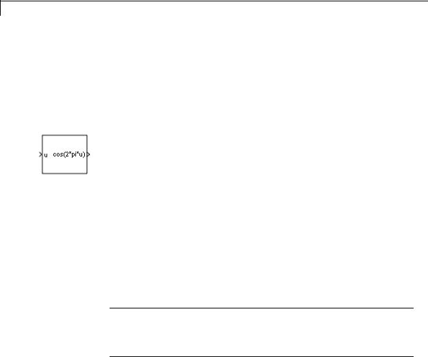
The Sine and Cosine block implements a sine and/or cosine wave in fixed point using a lookup table method that exploits quarter wave symmetry.
The Sine and Cosine block can output the following functions of the input signal, depending upon what you select for the Output formula parameter:
•sin(2πu)
•cos(2πu)
•exp(i2πu)
•sin(2πu) and cos(2πu)
You define the number of lookup table points in the Number of data points for lookup table parameter. The block implementation is most efficient when you specify the lookup table data points to be (2^n)+1, where n is an integer.
Tip To obtain meaningful block output, the block input values should fall within the range [0, 1). For input values that fall outside this range, the values are cast to an unsigned data type, where overflows wrap. For these out-of-range inputs, the block output might not be meaningful.
Use the Output word length parameter to specify the word length of the fixed-point output data type. The fraction length of the output is the output word length minus 2.
2-1578

Sine, Cosine
Data Type
Support
The Sine and Cosine block accepts signals of the following data types:
•Floating point
•Built-in integer
•Fixed point
•Boolean
The output of the block is a fixed-point data type.
For more information, see “Data Types Supported by Simulink” in the Simulink documentation.
2-1579
Sine, Cosine
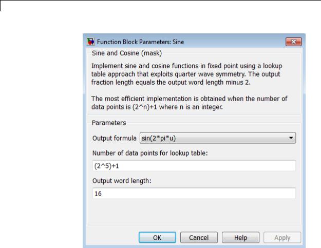
Parameters and Dialog Box
Output formula
Select the signal(s) to output.
Number of data points for lookup table
Specify the number of data points to retrieve from the lookup table. The implementation is most efficient when you specify the lookup table data points to be (2^n)+1, where n is an integer.
2-1580

Sine, Cosine
Output word length
Specify the word length for the fixed-point data type of the output signal. The fraction length of the output is the output word length minus 2.
Note The block uses double-precision floating-point values to construct lookup tables. Therefore, the maximum amount of precision you can achieve in your output is 53 bits. Setting the word length to values greater than 53 bits does not improve the precision of your output.
2-1581
Sine, Cosine
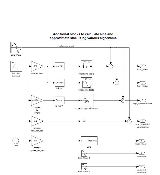
Examples The sldemo_tonegen_fixpt model shows how you can use the Sine block to implement a fixed-point sine wave.
2-1582
Sine, Cosine
Characteristics
See Also
Direct Feedthrough |
Yes |
Sample Time |
Inherited from the driving block |
Scalar Expansion |
N/A |
Zero-Crossing Detection |
No |
|
|
Sine Wave, Trigonometric Function
2-1583

Sine Wave
Purpose |
Generate sine wave, using simulation time as time source |
Library Sources
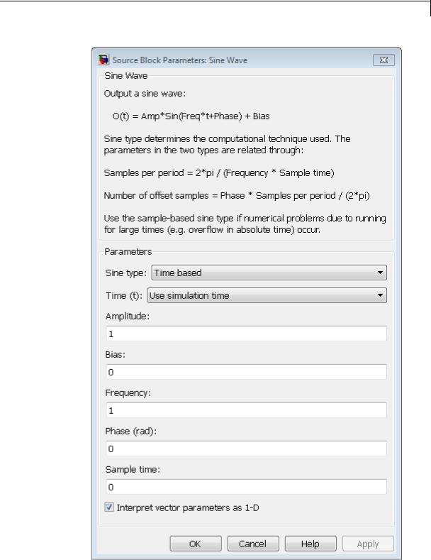
Description The Sine Wave block outputs a sinusoidal waveform. The block can operate in time-based or sample-based mode.
Note This block is the same as the Sine Wave Function block that appears in the Math Operations library. If you select Use external signal for the Time parameter in the block dialog box, you get the Sine Wave Function block.
Time-Based Mode
The output of the Sine Wave block is determined by:
y = amplitude × sin(frequency × time + phase) + bias.
Time-based mode has two submodes: continuous mode or discrete mode. The value of the Sample time parameter determines whether the block operates in continuous mode or discrete mode:
•0 (the default) causes the block to operate in continuous mode.
•>0 causes the block to operate in discrete mode.
See “Specify Sample Time” in the online documentation for more information.
Block Behavior in Continuous Mode
A Sample time parameter value of 0 causes the block to operate in continuous mode. When operating in continuous mode, the Sine Wave block can become inaccurate due to loss of precision as time becomes very large.
2-1584

Sine Wave
Block Behavior in Discrete Mode
A Sample time parameter value greater than zero causes the block to behave as if it were driving a Zero-Order Hold block whose sample time is set to that value.
Using the Sine Wave block in this way, you can build models with sine wave sources that are purely discrete, rather than models that are hybrid continuous/discrete systems. Hybrid systems are inherently more complex and as a result take more time to simulate.
In discrete mode, this block uses a differential incremental algorithm instead of one based on absolute time. As a result, the block can be useful in models intended to run for an indefinite length of time, such as in vibration or fatigue testing.
The differential incremental algorithm computes the sine based on the value computed at the previous sample time. This method uses the following trigonometric identities:
sin(t + |
t) = sin(t) cos( |
t) + sin( |
t) cos(t) |
|||
cos(t + |
t) = cos(t) cos( |
t) − sin(t)sin( |
t) |
|||
In matrix form, these identities are: |
|
|||||
sin(t + |
t) |
cos( |
t) |
sin( |
t) sin(t) |
|
|
|
= |
t) cos( |
|
|
|
cos(t + |
t) |
− sin( |
t) cos(t) |
|||
Because t is constant, the following expression is a constant:
cos( |
t) |
sin( |
t) |
|
|
− sin( |
t) |
cos( |
|
|
t) |
|||
Therefore, the problem becomes one of a matrix multiplication of the value of sin(t) by a constant matrix to obtain sin(t + t) .
Discrete mode reduces but does not eliminate the accumulation of round-off errors, for example, (4*eps). This accumulation can happen
2-1585

Sine Wave
because computation of the block output at each time step depends on the value of the output at the previous time step.
Methods to Handle Round-Off Errors in Discrete Mode
To handle round-off errors when the Sine Wave block operates in time-based discrete mode, use one of the following methods.
|
Method |
Rationale |
|
|
Insert a Saturation block directly |
By setting saturation limits on |
|
|
downstream of the Sine Wave |
the Sine Wave block output, you |
|
|
block. |
can remove overshoot due to |
|
|
|
accumulation of round-off errors. |
|
|
Set up the Sine Wave block to use |
Unlike the block algorithm, the |
|
|
the sin() math library function |
sin() math library function |
|
|
to calculate block output. |
computes block output at each |
|
|
|
time step independently of output |
|
|
1 On the Sine Wave block dialog |
values from other time steps, |
|
|
box, set Time to Use external |
preventing the accumulation of |
|
|
signal so that an input port |
round-off errors. |
|
|
appears on the block icon. |
|
|
|
2 Connect a clock signal to this |
|
|
|
input port using a Digital Clock |
|
|
|
block. |
|
|
|
3 Set the sample time of the |
|
|
|
clock signal to the sample time |
|
|
|
of the Sine Wave block. |
|
|
Sample-Based Mode
Sample-based mode uses the following formula to compute the output of the Sine Wave block.
y = Asin(2 (k + o) / p) + b
where
2-1586

Sine Wave
•A is the amplitude of the sine wave.
•p is the number of time samples per sine wave period.
•k is a repeating integer value that ranges from 0 to p–1.
•o is the offset (phase shift) of the signal.
•b is the signal bias.
In this mode, Simulink sets k equal to 0 at the first time step and computes the block output, using the preceding formula. At the next time step, Simulink increments k and recomputes the output of the block. When k reaches p, Simulink resets k to 0 before computing the block output. This process continues until the end of the simulation.
The sample-based method of computing the block output does not depend on the result of the previous time step to compute the result at the current time step. Therefore, this mode avoids the accumulation of round-off errors. However, this mode has one potential drawback. If the Sine Wave block is in a conditionally-executed subsystem that pauses and then resumes execution, the block output might not stay in sync with the rest of the simulation. If the accuracy of your model requires that the output of conditionally-executed Sine Wave blocks remain in sync with the rest of the model, use time-based mode for computing the output of the conditionally-executed blocks.
Parameter Dimensions
The numeric parameters of this block must have the same dimensions after scalar expansion.
•If Interpret vector parameters as 1-D is not selected, the block outputs a signal of the same dimensions and dimensionality as the parameters.
•If Interpret vector parameters as 1-D is selected and the numeric parameters are row or column vectors, the block outputs a vector signal. Otherwise, the block outputs a signal of the same dimensionality and dimensions as the parameters.
2-1587

Sine Wave
Data Type
Support
The Sine Wave block accepts and outputs real signals of type double.
For more information, see “Data Types Supported by Simulink” in the Simulink documentation.
2-1588
Sine Wave
2-1589
Parameters

Sine Wave
Time
Specify whether to use simulation time as the source of values for the time variable or an external source. If you specify an external time source, the block displays an input port for the time source.
Amplitude
Specify the amplitude of the signal. The default is 1.
Bias
Specify the constant value added to the sine to produce the output of this block.
Frequency
Specify the frequency, in radians per second. The default is 1. This parameter appears only when you set Sine type to time-based.
Samples per period
Specify the number of samples per period. This parameter appears only when you set Sine type to sample-based.
Phase
Specify the phase shift, in radians. The default is 0. This parameter appears only when you set Sine type to time-based.
Number of offset samples
Specify the offset (discrete phase shift) in number of sample times. This parameter appears only when you set Sine type to sample-based.
Sample time
Specify the sample period. The default is 0. If the sine type is sample-based, the sample time must be greater than 0. See “Specify Sample Time” in the online documentation for more information.
Interpret vector parameters as 1-D
If selected, column or row matrix values for numeric parameters result in a vector output signal. Otherwise, the block outputs
a signal of the same dimensionality as the parameters. If you do not select this check box, the block always outputs a signal of the same dimensionality as the numeric parameters. See
2-1590

Sine Wave
“Determining the Output Dimensions of Source Blocks” in the Simulink documentation. This parameter is not available when an external signal specifies time. In this case, if numeric parameters are column or row matrix values, the output is a 1-D vector.
Examples The following Simulink examples show how to use the Sine Wave block:
•sldemo_househeat
•sldemo_tonegen_fixpt
•sldemo_VariableTransportDelay
•sldemo_zeroxing
Characteristics |
Sample Time |
Specified in the Sample time |
|
|
parameter |
|
Scalar Expansion |
Yes, of parameters |
|
Dimensionalized |
Yes |
|
Zero-Crossing Detection |
No |
|
|
|
2-1591

Sine Wave Function
Purpose |
Generate sine wave, using external signal as time source |
Library |
Math Operations |
Description |
This block is the same as the Sine Wave block that appears in the |
|
Sources library. If you select Use simulation time for the Time |
|
parameter in the block dialog box, you get the Sine Wave block. See the |
|
documentation for the Sine Wave block for more information. |
2-1592
Slider Gain
Purpose
Library
Description
Data Type
Support
Parameters and Dialog Box
Vary scalar gain using slider
Math Operations
Use the Slider Gain block to vary a scalar gain during a simulation using a slider. The block accepts one input and generates one output.
Data type support for the Slider Gain block is the same as that for the Gain block (see Gain).
Low
Specify the lower limit of the slider range. The default is 0.
High
Specify the upper limit of the slider range. The default is 2.
The edit fields indicate (from left to right) the lower limit, the current value, and the upper limit. You can change the gain in two ways: by manipulating the slider, or by entering a new value in the current value field. You can change the range of gain values by changing the lower and upper limits. Close the dialog box by clicking the Close button.
If you click the left or right arrow of the slider, the current value changes by about 1% of the slider range. If you click the rectangular area to either side of the slider’s indicator, the current value changes by about 10% of the slider range.
To apply a vector or matrix gain to the block input, consider using the Gain block.
2-1593

Slider Gain
Examples |
The following example models show how to use the Slider Gain block: |
||
|
|
• aero_six_dof |
|
Characteristics |
|
|
|
|
Direct Feedthrough |
Yes |
|
|
|
Sample Time |
Inherited from the driving block |
|
|
Scalar Expansion |
Yes, of the gain |
|
|
States |
0 |
|
|
Dimensionalized |
Yes |
|
|
Multidimensionalized |
Yes |
|
|
Zero-Crossing Detection |
No |
See Also |
|
Gain |
|
2-1594
Sqrt, Signed Sqrt, Reciprocal Sqrt
Purpose
Library
Description
Calculate square root, signed square root, or reciprocal of square root
Math Operations
You can select one of the following functions from the Function parameter list.
|
Function |
Description |
Mathematical |
MATLAB |
|
|
|
|
Expression |
Equivalent |
|
|
sqrt |
Square root of |
u0.5 |
sqrt |
|
|
|
the input |
|
|
|
|
signedSqrt |
Square root of |
sign(u)*|u|0.5 |
— |
|
|
|
the absolute |
|
|
|
|
|
value of |
|
|
|
|
|
the input, |
|
|
|
|
|
multiplied by |
|
|
|
|
|
the sign of the |
|
|
|
|
|
input |
|
|
|
|
rSqrt |
Reciprocal of |
u-0.5 |
— |
|
|
|
the square root |
|
|
|
|
|
of the input |
|
|
|
The block output is the result of applying the function to the input. Each function supports:
•Scalar operations
•Element-wise vector and matrix operations
2-1595

Sqrt, Signed Sqrt, Reciprocal Sqrt
Data Type
Support
The block accepts input signals of the following data types:
|
Function |
Input Data Types |
Restrictions |
|
|
sqrt |
• Floating point |
None |
|
|
|
• Built-in integer |
|
|
|
|
• Fixed point |
|
|
|
signedSqrt |
• Floating point |
When the input is an |
|
|
|
• Built-in integer |
integer or fixed-point |
|
|
|
type, the output must |
|
|
|
|
|
|
|
|
|
• Fixed point |
be floating point. |
|
|
rSqrt |
• Floating point |
None |
|
|
|
• Built-in integer |
|
|
|
|
• Fixed point |
|
|
|
|
|
|
|
The block accepts real and complex inputs of the following types:
Function |
Types of Real |
Types of Complex |
|
|
Inputs |
Inputs |
|
sqrt |
Any, except for |
Any, except for |
|
|
fixed-point inputs |
fixed-point inputs |
|
|
that are negative or |
|
|
signedSqrt |
None |
||
have nontrivial slope |
|||
|
|
||
|
None |
||
rSqrt |
and nonzero bias |
||
|
|
|
|
The block output: |
|
|
•Uses the data type that you specify for Output data type
•Is real or complex, depending on your selection for Output signal type
2-1596
Sqrt, Signed Sqrt, Reciprocal Sqrt
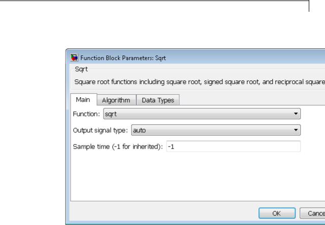
Parameters The Main pane of the block dialog box appears as follows:
and Dialog Box
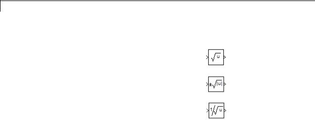
Function
Specify the mathematical function. The block icon changes to match the function you select.
2-1597
Sqrt, Signed Sqrt, Reciprocal Sqrt
|
Function |
Block Icon |
|
|
sqrt |
|
|
|
|
|
|
|
signedSqrt |
|
|
|
|
|
|
|
rSqrt |
|
|
|
|
|
|
Output signal type
Specify the output signal type of the block as auto, real, or complex.
|
Function |
Input Signal |
|
Output Signal Type |
|
||
|
|
Type |
|
|
|
|
|
|
|
Auto |
|
Real |
Complex |
|
|
|
|
|
|
|
|||
|
sqrt |
real |
real for |
|
real for |
complex |
|
|
|
|
nonnegative |
|
nonnegative |
|
|
|
|
|
inputs |
|
inputs |
|
|
|
|
|
nan for negative |
nan for negative |
|
|
|
|
|
|
inputs |
|
inputs |
|
|
|
|
complex |
complex |
|
error |
complex |
|
|
signedSqrt |
real |
real |
|
real |
complex |
|
|
|
complex |
error |
|
error |
error |
|
|
rSqrt |
real |
real |
|
real |
error |
|
|
|
complex |
error |
|
error |
error |
|
|
|
|
|
|
|
|
|
Sample time (-1 for inherited)
Specify the time interval between samples. To inherit the sample time, set this parameter to -1. See “Specify Sample Time” in the online documentation for more information.
2-1598
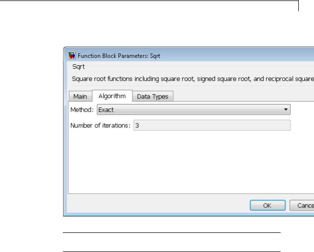
Sqrt, Signed Sqrt, Reciprocal Sqrt
The Algorithm pane of the block dialog box appears as follows:
Note The parameters in the Algorithm pane are available only when you set Function to rSqrt on the Main pane.
Method
Specify the method for computing the reciprocal of a square root.
2-1599

Sqrt, Signed Sqrt, Reciprocal Sqrt
|
Method |
Data Types |
|
When to Use This |
|
|
|
|
Supported |
|
Method |
|
|
|
Exact |
Floating point |
|
You do not want an |
|
|
|
|
If you use a |
|
approximation. |
|
|
|
|
|
|
|
|
|
|
|
fixed-point or |
|
|
|
|
|
|
built-in integer |
|
|
|
|
|
|
|
Note The input |
|
||
|
|
type, an upcast to a |
|
|
||
|
|
floating-point type |
|
or output must be |
|
|
|
|
|
floating point. |
|
||
|
|
occurs. |
|
|
||
|
|
|
|
|
|
|
|
Newton-Raphson |
Floating-point, |
|
You want a fast, |
|
|
|
|
fixed-point, and |
|
approximate |
|
|
|
|
built-in integer |
|
calculation. |
|
|
|
|
types |
|
|
|
|
The Exact method provides results that are consistent with MATLAB computations.
Note The algorithms for sqrt and signedSqrt are always of Exact type, no matter what selection appears on the block dialog box.
Number of iterations
Specify the number of iterations to perform the Newton-Raphson algorithm. The default value is 3.
This parameter is not available when you select Exact for
Method.
Note If you enter 0, the block output is the initial guess of the Newton-Raphson algorithm.
2-1600
Sqrt, Signed Sqrt, Reciprocal Sqrt
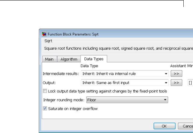
The Data Types pane of the block dialog box appears as follows:
Intermediate results data type
Specify the data type for intermediate results (available only when you set Function to sqrt or rSqrt on the Main pane). You can set the data type to:
•A rule that inherits a data type, for example, Inherit:Inherit via internal rule
•The name of a built-in data type, for example, single
•The name of a data type object, for example, a
Simulink.NumericType object
2-1601

Sqrt, Signed Sqrt, Reciprocal Sqrt
•An expression that evaluates to a data type, for example, fixdt(1,16,0)
Follow these guidelines on setting an intermediate data type explicitly for the square root function, sqrt:
|
Input and Output Data |
Intermediate Data Type |
|
|
Types |
|
|
|
Input or output is double. |
Use double. |
|
|
Input or output is single, and |
Use single or double. |
|
|
any non-single data type is not |
|
|
|
double. |
|
|
|
Input and output are fixed |
Use fixed point. |
|
|
point. |
|
|
Follow these guidelines on setting an intermediate data type explicitly for the reciprocal square root function, rSqrt:
|
Input and Output Data |
Intermediate Data Type |
|
|
Types |
|
|
|
Input is double and output is |
Use double. |
|
|
not single. |
|
|
|
Input is not single and output |
Use double. |
|
|
is double. |
|
|
|
Input and output are fixed |
Use fixed point. |
|
|
point. |
|
|
2-1602
Sqrt, Signed Sqrt, Reciprocal Sqrt
Caution Do not set Intermediate results data type to
Inherit:Inherit from output when:
•You select Newton-Raphson to compute the reciprocal of a square root.
•The input data type is floating point.
•The output data type is fixed point.
Under these conditions, selecting Inherit:Inherit from output yields suboptimal performance and produces an error.
To avoid this error, convert the input signal from a floating-point to fixed-point data type. For example, insert a Data Type Conversion block in front of the Sqrt block to perform the conversion.
Output data type
Specify the output data type. You can set the data type to:
•A rule that inherits a data type, for example, Inherit:Inherit via back propagation
•The name of a built-in data type, for example, single
•The name of a data type object, for example, a
Simulink.NumericType object
•An expression that evaluates to a data type, for example, fixdt(1,16,0)
Click the Show data type assistant button  to display the Data Type Assistant, which helps you set the
Output data type parameter.
See “Specify Block Output Data Types” in the Simulink User’s Guide for more information.
2-1603

Sqrt, Signed Sqrt, Reciprocal Sqrt
Output minimum
Specify the minimum value that the block can output. The default value is [] (unspecified). Simulink uses this value to perform:
•Simulation range checking (see “Signal Ranges”)
•Automatic scaling of fixed-point data types
Output maximum
Specify the maximum value that the block can output. The default value is [] (unspecified). Simulink uses this value to perform:
•Simulation range checking (see “Signal Ranges”)
•Automatic scaling of fixed-point data types
Lock output data type setting against changes by the fixed-point tools
Select to lock the output data type setting of this block against changes by the Fixed-Point Tool and the Fixed-Point Advisor. For more information, see “Use Lock Output Data Type Setting”.
Integer rounding mode
Specify the rounding mode for fixed-point operations. For more information, see “Rounding”. in the Simulink Fixed Point documentation.
Saturate on integer overflow
|
Action |
Reasons for Taking |
What Happens for |
Example |
|
|
This Action |
Overflows |
|
|
Select this |
Your model has |
Overflows saturate to |
An overflow associated |
|
check box. |
possible overflow, |
either the minimum |
with a signed 8-bit |
|
|
and you want explicit |
or maximum value |
|
|
|
|
|
|
2-1604

Sqrt, Signed Sqrt, Reciprocal Sqrt
Action |
Reasons for Taking |
What Happens for |
Example |
|
This Action |
Overflows |
|
|
|
|
integer can saturate to |
|
saturation protection |
that the data type can |
|
|
in the generated code. |
represent. |
–128 or 127. |
|
|
|
|
Do not select |
You want to optimize |
Overflows wrap to the |
The number 130 does |
this check |
efficiency of your |
appropriate value that |
not fit in a signed 8-bit |
box. |
generated code. |
is representable by the |
integer and wraps to |
|
You want to avoid |
data type. |
–126. |
|
|
|
|
|
overspecifying how |
|
|
|
a block handles |
|
|
|
out-of-range signals. |
|
|
|
For more information, |
|
|
|
see “Checking for |
|
|
|
Signal Range Errors”. |
|
|
|
When you select this check box, saturation applies to every |
||
|
internal operation on the block, not just the output or result. |
||
|
Usually, the code generation process can detect when overflow is |
||
|
not possible. In this case, the code generator does not produce |
||
|
saturation code. |
|
|
2-1605

Sqrt, Signed Sqrt, Reciprocal Sqrt
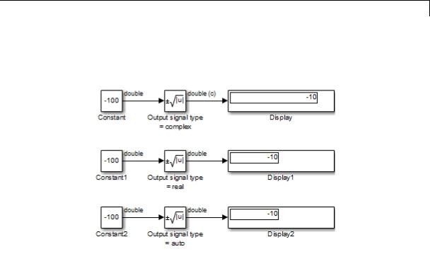
Examples |
sqrt Function |
|
Suppose that you have the following model: |
When the input to the Sqrt block is negative and the Output signal type is auto or real, the sqrt function outputs nan. However, setting Output signal type to complex produces the correct answer.
2-1606
Sqrt, Signed Sqrt, Reciprocal Sqrt
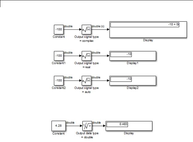
signedSqrt Function
Suppose that you have the following model:
When the input to the Sqrt block is negative, the block output is the same for any Output signal type setting. If you change the first Display block format from short to decimal (Stored Integer), you see the value of the imaginary part for the complex output.
2-1607
Sqrt, Signed Sqrt, Reciprocal Sqrt
rSqrt Function with Floating-Point Inputs
Suppose that you have the following model:
In the Sqrt block dialog box, assume that the following parameter settings apply:
|
Parameter |
Setting |
|
|
Method |
Newton-Raphson |
|
|
Number of iterations |
1 |
|
|
Intermediate results data |
Inherit:Inherit from input |
|
|
type |
|
|
2-1608
Sqrt, Signed Sqrt, Reciprocal Sqrt
After one iteration of the Newton-Raphson algorithm, the block output is within 0.0004 of the final value (0.4834).
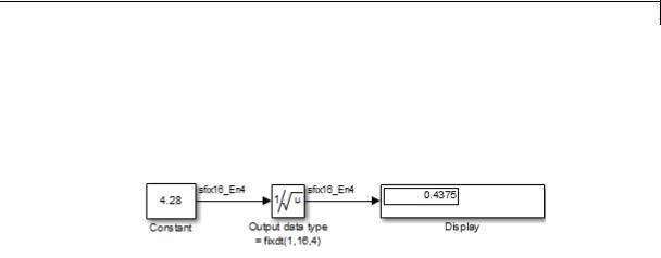
rSqrt Function with Fixed-Point Inputs
Suppose that you have the following model:
In the Sqrt block dialog box, assume that the following parameter settings apply:
|
|
Parameter |
|
Setting |
|
|
|
Method |
|
Newton-Raphson |
|
|
|
Number of iterations |
|
1 |
|
|
|
Intermediate results data |
|
Inherit:Inherit from input |
|
|
|
type |
|
|
|
|
|
After one iteration of the Newton-Raphson algorithm, the block output |
|
||
|
|
is within 0.0459 of the final value (0.4834). |
|
||
Characteristics |
|
|
|
|
|
|
Direct Feedthrough |
Yes |
|
||
|
|
Sample Time |
Specified in the Sample time |
|
|
|
|
|
parameter |
|
|
|
|
Dimensionalized |
Yes |
|
|
|
|
Multidimensionalized |
Yes |
|
|
|
|
Zero-Crossing Detection |
No |
|
|
See Also |
|
Math Function, Trigonometric Function |
|
||
2-1609
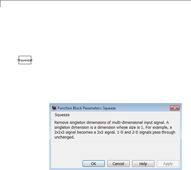
Squeeze
Purpose |
Remove singleton dimensions from multidimensional signal |
Library |
Math Operations |
Description |
The Squeeze block removes singleton dimensions from its |
|
multidimensional input signal. A singleton dimension is any dimension |
|
whose size is one. The Squeeze block operates only on signals whose |
|
number of dimensions is greater than two. Scalar, one-dimensional |
|
(vector), and two-dimensional (matrix) signals pass through the Squeeze |
|
block unchanged. |
Data Type
Support
The Squeeze block accepts input signals of any dimension and of any data type that Simulink supports, including fixed-point and enumerated data types. For more information, see “Data Types Supported by Simulink” in the Simulink documentation.
Parameters and Dialog Box
2-1610
Squeeze
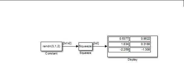
Examples
In the following model, the Squeeze block converts a multidimensional array of size 3-by-1-by-2 into a 3-by-2 signal:
Because the Constant block supplies a signal with random values to the Squeeze block, the values in the Display block vary from simulation to simulation.
Characteristics
See Also
Direct Feedthrough |
Yes |
Sample Time |
Inherited from the driving block |
Scalar Expansion |
N/A |
Dimensionalized |
Yes |
Multidimensionalized |
Yes |
Zero-Crossing Detection |
No |
|
|
Reshape
2-1611
State-Space
Purpose |
Implement linear state-space system |
Library Continuous
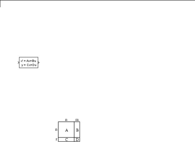
Description The State-Space block implements a system whose behavior you define as
x = Ax + Bu
y = Cx + Du,
where x is the state vector, u is the input vector, and y is the output vector. The matrix coefficients must have these characteristics:
•A must be an n-by-n matrix, where n is the number of states.
•B must be an n-by-m matrix, where m is the number of inputs.
•C must be an r-by-n matrix, where r is the number of outputs.
•D must be an r-by-m matrix.
The block accepts one input and generates one output. The input vector width depends on the number of columns in the B and D matrices. The output vector width depends on the number of rows in the C and D matrices.
Simulink software converts a matrix containing zeros to a sparse matrix for efficient multiplication.
Data Type A State-Space block accepts and outputs real signals of type double.
Support For more information, see “Data Types Supported by Simulink” in the Simulink documentation.
2-1612
State-Space
Parameters and Dialog Box
2-1613

State-Space
A
Specify the n-by-n matrix coefficient, where n is the number of states.
Settings
Default: 1
Command-Line Information
See “Block-Specific Parameters” on page 8-109 for the command-line information.
2-1614

State-Space
B
Specify the n-by-m matrix coefficient, where n is the number of states and m is the number of inputs.
Settings
Default: 1
Command-Line Information
See “Block-Specific Parameters” on page 8-109 for the command-line information.
2-1615

State-Space
C
Specify the r-by-n matrix coefficient, where r is the number of outputs and n is the number of states.
Settings
Default: 1
Command-Line Information
See “Block-Specific Parameters” on page 8-109 for the command-line information.
2-1616

State-Space
D
Specify the r-by-m matrix coefficient, where r is the number of outputs and m is the number of inputs.
Settings
Default: 1
Command-Line Information
See “Block-Specific Parameters” on page 8-109 for the command-line information.
2-1617

State-Space
Initial conditions
Specify the initial state vector.
Settings
Default: 0
The initial conditions of this block cannot be inf or NaN.
Command-Line Information
See “Block-Specific Parameters” on page 8-109 for the command-line information.
2-1618

State-Space
Absolute tolerance
Specify the absolute tolerance for computing block states.
Settings
Default: auto
•You can enter auto, 1, a real scalar, or a real vector.
•If you enter auto or 1, then Simulink uses the absolute tolerance value in the Configuration Parameters dialog box (see “Solver Pane”) to compute block states.
•If you enter a real scalar, then that value overrides the absolute tolerance in the Configuration Parameters dialog box for computing all block states.
•If you enter a real vector, then the dimension of that vector must match the dimension of the continuous states in the block. These values override the absolute tolerance in the Configuration Parameters dialog box.
Command-Line Information
See “Block-Specific Parameters” on page 8-109 for the command-line information.
2-1619

State-Space
State Name (e.g., ’position’)
Assign a unique name to each state.
Settings
Default: ' '
If this field is blank, no name assignment occurs.
Examples
Tips
•To assign a name to a single state, enter the name between quotes, for example, 'velocity'.
•To assign names to multiple states, enter a comma-delimited list surrounded by braces, for example, {'a', 'b', 'c'}. Each name must be unique.
•The state names apply only to the selected block.
•The number of states must divide evenly among the number of state names.
•You can specify fewer names than states, but you cannot specify more names than states.
For example, you can specify two names in a system with four states. The first name applies to the first two states and the second name to the last two states.
•To assign state names with a variable in the MATLAB workspace, enter the variable without quotes. A variable can be a string, cell array, or structure.
Command-Line Information
See “Block-Specific Parameters” on page 8-109 for the command-line information.
The following Simulink examples show how to use the State-Space block:
• sldemo_dblcart1
2-1620

State-Space
|
|
• aero_vibrati |
|
Characteristics |
|
|
|
|
Direct Feedthrough |
Only if D ≠ 0 |
|
|
|
Sample Time |
Continuous |
|
|
Scalar Expansion |
Yes, of the initial conditions |
|
|
States |
Depends on the size of A |
|
|
Dimensionalized |
Yes |
|
|
Zero-Crossing Detection |
No |
See Also |
|
Discrete State-Space |
|
2-1621

Step
Purpose |
Generate step function |
Library |
Sources |
Description |
The Step block provides a step between two definable levels at a |
|
specified time. If the simulation time is less than the Step time |
|
parameter value, the block’s output is the Initial value parameter |
|
value. For simulation time greater than or equal to the Step time, the |
|
output is the Final value parameter value. |
|
The numeric block parameters must be of the same dimensions |
|
after scalar expansion. If the Interpret vector parameters as |
|
1-D option is off, the block outputs a signal of the same dimensions |
|
and dimensionality as the parameters. If the Interpret vector |
|
parameters as 1-D option is on and the numeric parameters are row |
|
or column vectors (that is, single row or column 2-D arrays), the block |
|
outputs a vector (1-D array) signal. Otherwise, the block outputs a |
|
signal of the same dimensionality and dimensions as the parameters. |
Data Type |
The Step block outputs real signals of type double. |
Support |
For more information, see “Data Types Supported by Simulink” in the |
|
Simulink documentation. |
2-1622
Step
Parameters and Dialog Box
Step time
Specify the time, in seconds, when the output jumps from the Initial value parameter to the Final value parameter. The default is 1 second.
Initial value
Specify the block output until the simulation time reaches the Step time parameter. The default is 0.
2-1623

Step
Final value
Specify the block output when the simulation time reaches and exceeds the Step time parameter. The default is 1.
Sample time
Specify the sample rate of step. See “Specify Sample Time” in the online documentation for more information.
Interpret vector parameters as 1-D
|
|
If selected, column or row matrix values for the Step block’s |
|
|
|
numeric parameters result in a vector output signal; otherwise, |
|
|
|
the block outputs a signal of the same dimensionality as the |
|
|
|
parameters. If this option is not selected, the block always |
|
|
|
outputs a signal of the same dimensionality as the block’s numeric |
|
|
|
parameters. See “Determining the Output Dimensions of Source |
|
|
|
Blocks” in the Simulink documentation. |
|
|
|
Enable zero-crossing detection |
|
|
|
Select to enable zero-crossing detection. For more information, |
|
|
|
see “Zero-Crossing Detection” in the Simulink documentation. |
|
Examples |
The following Simulink examples show how to use the Step block: |
||
|
|
• sldemo_doublebounce |
|
|
|
• sldemo_enginewc |
|
Characteristics |
|
|
|
|
Sample Time |
Specified in the Sample time |
|
|
|
|
parameter |
|
|
Scalar Expansion |
Yes, of parameters |
|
|
Dimensionalized |
Yes |
|
|
Zero-Crossing Detection |
Yes, if enabled. |
See Also |
|
Ramp |
|
2-1624
Stop Simulation
Purpose |
Stop simulation when input is nonzero |
Library Sinks
Description The Stop Simulation block stops the simulation when the input is nonzero. The simulation completes the current time step before terminating. If the block input is a vector, any nonzero vector element causes the simulation to stop.
When you use the Stop Simulation block in a For Iterator subsystem, the stop action occurs after execution of all the iterations in the subsystem during a time step. The stop action does not interrupt execution until the start of the next time step.
You cannot use the Stop Simulation block to pause the simulation. To create a block that pauses the simulation, see “Creating Pause Blocks” in the Simulink documentation.
Data Type The Stop Simulation block accepts real signals of type double or
Support Boolean. For more information, see “Data Types Supported by Simulink” in the Simulink documentation.
Parameters and Dialog Box
2-1625
Stop Simulation
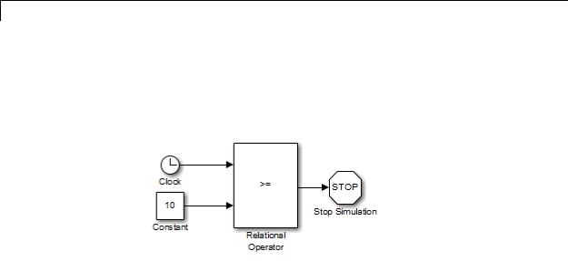
Examples Usage with the Relational Operator Block
You can use the Stop Simulation block with the Relational Operator block to control when a simulation stops. For example, the following model stops simulation when the simulation time reaches 10.
2-1626
Stop Simulation
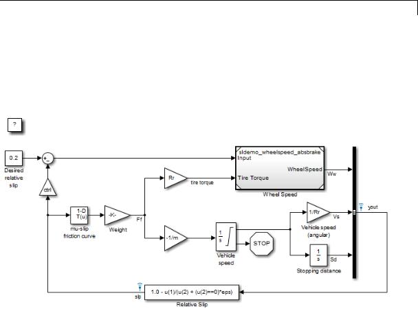
Usage with the Integrator Block
You can use the Stop Simulation block with the Integrator block to control when a simulation stops. For example, the sldemo_absbrake model stops simulation when the saturation port of the Integrator block outputs a value of 1 or –1.
Characteristics |
Sample Time |
Inherited from driving block |
|
Dimensionalized |
Yes |
|
Zero-Crossing Detection |
No |
|
|
|
2-1627

Subsystem, Atomic Subsystem, Nonvirtual Subsystem,
CodeReuse Subsystem
Purpose
Library
Description
Represent system within another system
Ports & Subsystems
A Subsystem block represents a subsystem of the system that contains it. The Subsystem block can represent a virtual subsystem or a nonvirtual subsystem. The primary difference is that nonvirtual subsystems provide the ability to control when the contents of the subsystem are evaluated. Nonvirtual subsystems are executed as a single unit (atomic execution) by the Simulink engine. A subsystem is virtual unless the block is conditionally executed and/or you have selected the Treat as atomic unit check box.
Tip To determine if a subsystem is virtual, use the get_param function to obtain the value of the IsSubsystemVirtual property for the block. This property returns a read-only Boolean value for the block. See “Block-Specific Parameters” on page 8-109 for the subsystem block that interests you.
An Atomic Subsystem block is a Subsystem block where Treat as atomic unit is selected by default. You can create conditionally executed nonvirtual subsystems that are executed only when a transition occurs on a triggering, function-call, action, or enabling input (see “Conditional Subsystems”).
You can create a subsystem in these ways:
•Copy the Subsystem (or Atomic Subsystem) block from the Ports & Subsystems library into your model. You can then add blocks to the subsystem by opening the Subsystem block and copying blocks into its window.
•Select the blocks and lines that are to make up the subsystem using a bounding box, then choose Diagram > Subsystem & Model Reference > Create Subsystem from Selection from the model window menu. Simulink software replaces the blocks with a
2-1628

Subsystem, Atomic Subsystem, Nonvirtual Subsystem,
CodeReuse Subsystem
Data Type
Support
Subsystem block. When you open the block, the window displays the blocks you selected, adding Inport and Outport blocks to reflect signals entering and leaving the subsystem.
The number of input ports drawn on the Subsystem block’s icon corresponds to the number of Inport blocks in the subsystem. Similarly, the number of output ports drawn on the block corresponds to the number of Outport blocks in the subsystem.
The Subsystem block supports signal label propagation through subsystem Inport and Outport blocks.
See “Create a Subsystem” in the Simulink documentation for more information about subsystems.
See Inport for information on the data types accepted by a subsystem’s input ports. See Outport for information on the data types output by a subsystem’s output ports.
For more information, see “Data Types Supported by Simulink” in the Simulink documentation.
2-1629

Subsystem, Atomic Subsystem, Nonvirtual Subsystem,
CodeReuse Subsystem
Parameters and Dialog Box
2-1630
Subsystem, Atomic Subsystem, Nonvirtual Subsystem,
CodeReuse Subsystem
2-1631
Subsystem, Atomic Subsystem, Nonvirtual Subsystem,
CodeReuse Subsystem
Note Parameters on the Code Generation tab require a Simulink Coder or Embedded Coder license. For more information, see the parameter sections.
2-1632
Subsystem, Atomic Subsystem, Nonvirtual Subsystem,
CodeReuse Subsystem
Show port labels
Cause Simulink software to display labels for the subsystem’s ports on the subsystem’s icon.
Settings
Default: FromPortIcon
none
Does not display port labels on the subsystem block.
FromPortIcon
If the corresponding port icon displays a signal name, display the signal name on the subsystem block. Otherwise, display the port block’s name.
FromPortBlockName
Display the name of the corresponding port block on the subsystem block.
SignalName
If a name exists, display the name of the signal connected to the port on the subsystem block; otherwise, the name of the corresponding port block.
Command-Line Information
See “Block-Specific Parameters” on page 8-109 for the command-line information.
2-1633

Subsystem, Atomic Subsystem, Nonvirtual Subsystem,
CodeReuse Subsystem
Read/Write permissions
Control user access to the contents of the subsystem.
Settings
Default: ReadWrite
ReadWrite
Enables opening and modification of subsystem contents.
ReadOnly
Enables opening but not modification of the subsystem. If the subsystem resides in a block library, you can create and open links to the subsystem and can make and modify local copies of the subsystem but cannot change the permissions or modify the contents of the original library instance.
NoReadOrWrite
Disables opening or modification of subsystem. If the subsystem resides in a library, you can create links to the subsystem in a model but cannot open, modify, change permissions, or create local copies of the subsystem.
Command-Line Information
See “Block-Specific Parameters” on page 8-109 for the command-line information.
2-1634

Subsystem, Atomic Subsystem, Nonvirtual Subsystem,
CodeReuse Subsystem
Name of error callback function
Enter name of a function to be called if an error occurs while Simulink software is executing the subsystem.
Settings
Default: ' '
Simulink software passes two arguments to the function: the handle of the subsystem and a string that specifies the error type. If no function is specified, Simulink software displays a generic error message if executing the subsystem causes an error.
Command-Line Information
See “Block-Specific Parameters” on page 8-109 for the command-line information.
2-1635

Subsystem, Atomic Subsystem, Nonvirtual Subsystem,
CodeReuse Subsystem
Permit hierarchical resolution
Specify whether to resolve names of workspace variables referenced by this subsystem.
Settings
Default: All
All
Resolve all names of workspace variables used by this subsystem, including those used to specify block parameter values and Simulink data objects (for example, Simulink.Signal objects).
ExplicitOnly
Resolve only names of workspace variables used to specify block parameter values, data store memory (where no block exists), signals, and states marked as “must resolve”.
None
Do not resolve any workspace variable names.
Command-Line Information
See “Block-Specific Parameters” on page 8-109 for the command-line information.
2-1636

Subsystem, Atomic Subsystem, Nonvirtual Subsystem,
CodeReuse Subsystem
Treat as atomic unit
Causes Simulink software to treat the subsystem as a unit when determining the execution order of block methods.
Settings
Default: Off
 On
On
Cause Simulink software to treat the subsystem as a unit when determining the execution order of block methods. For example, when it needs to compute the output of the subsystem, Simulink software invokes the output methods of all the blocks in the subsystem before invoking the output methods of other blocks at the same level as the subsystem block.
 Off
Off
Cause Simulink software to treat all blocks in the subsystem as being at the same level in the model hierarchy as the subsystem when determining block method execution order. This can cause execution of methods of blocks in the subsystem to be interleaved with execution of methods of blocks outside the subsystem.
Dependencies
This parameter enables:
•“Minimize algebraic loop occurrences” on page 2-1638.
•“Sample time (-1 for inherited)” on page 2-1641
•“Function packaging” on page 2-1642 (requires a Simulink Coder license)
Command-Line Information
See “Block-Specific Parameters” on page 8-109 for the command-line information.
2-1637

Subsystem, Atomic Subsystem, Nonvirtual Subsystem,
CodeReuse Subsystem
Minimize algebraic loop occurrences
Try to eliminate any artificial algebraic loops that include the atomic subsystem
Settings
Default: Off
 On
On
Try to eliminate any artificial algebraic loops that include the atomic subsystem.
 Off
Off
Do not try to eliminate any artificial algebraic loops that include the atomic subsystem.
Dependency
“Treat as atomic unit” on page 2-1637 enables this parameter.
Command-Line Information
See “Block-Specific Parameters” on page 8-109 for the command-line information.
2-1638

Subsystem, Atomic Subsystem, Nonvirtual Subsystem,
CodeReuse Subsystem
Propagate execution context across subsystem boundary
Enable execution context propagation across the boundary of this subsystem.
Settings
Default: Off
 On
On
Enables execution context propagation across this subsystem’s boundary.
 Off
Off
Does not enable execution context propagation across this subsystem’s boundary.
Dependency
Conditional execution of the subsystem enables this parameter.
Command-Line Information
See “Block-Specific Parameters” on page 8-109 for the command-line information.
2-1639

Subsystem, Atomic Subsystem, Nonvirtual Subsystem,
CodeReuse Subsystem
Warn if function-call inputs are context-specific
Simulink displays a warning if it has to compute any of this function-call subsystem’s inputs directly or indirectly during execution of a function-call.
Settings
Default: Off
 On
On
Simulink displays a warning if it has to compute any of this function-call subsystem’s inputs directly or indirectly during execution of a function-call.
 Off
Off
Simulink does not display a warning if it has to compute any of this function-call subsystem’s inputs directly or indirectly during execution of a function-call.
Dependency
Use of a function-call subsystem enables this parameter.
The option is effective only when the Context-dependent inputs diagnostic on the Diagnostics > Connectivity pane of the Configuration Parameters dialog box is set to Use local settings.
Command-Line Information
See “Block-Specific Parameters” on page 8-109 for the command-line information.
2-1640

Subsystem, Atomic Subsystem, Nonvirtual Subsystem,
CodeReuse Subsystem
Sample time (-1 for inherited)
Specify whether all blocks in this subsystem must run at the same rate or can run at different rates.
Settings
Default: -1
•-1
Specify the inherited sample time. Use this sample time if the blocks in the subsystem can run at different rates.
•[Ts 0]
Specify periodic sample time.
Tips
•If the blocks in the subsystem can run at different rates, specify the subsystem’s sample time as inherited (-1).
•If all blocks must run at the same rate, specify the sample time corresponding to this rate as the value of the subsystem’s Sample time parameter.
•If any of the blocks in the subsystem specify a different sample time (other than -1 or inf), Simulink software displays an error message when you update or simulate the model. For example, suppose all the blocks in the subsystem must run 5 times a second. To ensure this, specify the sample time of the subsystem as 0.2. In this example, if any of the blocks in the subsystem specify a sample time other than
0.2, -1, or inf, Simulink software displays an error when you update or simulate the model.
Dependency
“Treat as atomic unit” on page 2-1637 enables this parameter.
Command-Line Information
See “Block-Specific Parameters” on page 8-109 for the command-line information.
2-1641

Subsystem, Atomic Subsystem, Nonvirtual Subsystem,
CodeReuse Subsystem
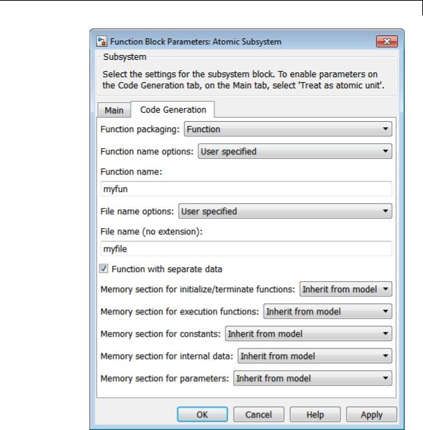
Function packaging
Specify the code format to be generated for an atomic (nonvirtual) subsystem.
Settings
Default: Auto
Auto
Simulink Coder software chooses the optimal format for you based on the type and number of instances of the subsystem that exist in the model.
Inline
Simulink Coder software inlines the subsystem unconditionally.
Function
Simulink Coder software explicitly generates a separate function with no arguments, and optionally places the subsystem code in a separate file. You can name the generated function and file.
Functions created with this option rely on global data. Therefore, these functions are not reentrant.
Reusable function
Simulink Coder software generates a function with arguments that allows reuse of subsystem code when a model includes multiple instances of the subsystem.
This option also generates a function with arguments that allows subsystem code to be reused in the generated code of a model reference hierarchy that includes multiple instances of a subsystem across referenced models. In this case, the subsystem must be in a library.
Tips
•When you want multiple instances of a subsystem to be represented as one reusable function, you can designate each one of them as Auto or as Reusable function. It is best to use one or the other, as using both creates two reusable functions, one for each designation. The outcomes of these choices differ only when reuse is not possible.
2-1642
Subsystem, Atomic Subsystem, Nonvirtual Subsystem,
CodeReuse Subsystem
Selecting Auto does not allow control of the function or file name for the subsystem code.
•The Reusable function and Auto options both try to determine if multiple instances of a subsystem exist and if the code can be reused. The difference between the options’ behavior is that when reuse is not possible:
-Auto yields inlined code, or if circumstances prohibit inlining, separate functions without arguments for reach subsystem instance.
-Reusable function yields a separate function with arguments for each subsystem instance in the model.
•If you select Reusable function while your generated code is under source control, set File name options to Use subsystem name, Use function name, or User specified. Otherwise, the names of your code files change whenever you modify your model, which prevents source control on your files.
Dependencies
•This parameter requires a Simulink Coder license.
•“Treat as atomic unit” on page 2-1637 enables this parameter.
•Setting this parameter to Function or Reusable function enables the following parameters:
-
-
-
“Function name options” on page 2-1645 “File name options” on page 2-1648
“Memory section for initialize/terminate functions” on page 2-1652 (requires a license for Embedded Coder software and an ERT-based system target file)
-“Memory section for execution functions” on page 2-1654 (requires a license for Embedded Coder software and an ERT-based system target file)
2-1643

Subsystem, Atomic Subsystem, Nonvirtual Subsystem,
CodeReuse Subsystem
•Setting this parameter to Function enables “Function with separate data” on page 2-1651 (requires a license for Embedded Coder software and an ERT-based system target file).
Command-Line Information
See “Block-Specific Parameters” on page 8-109 for the command-line information.
2-1644

Subsystem, Atomic Subsystem, Nonvirtual Subsystem,
CodeReuse Subsystem
Function name options
Specify how Simulink Coder software is to name the function it generates for the subsystem.
Settings
Default: Auto
Auto
Assign a unique function name using the default naming convention, model_subsystem(), where model is the name of the model and subsystem is the name of the subsystem (or that of an identical one when code is being reused).
If you select Reusable function for the Function packaging parameter and there are multiple instances of the reusable subsystem in a model reference hierarchy, in order to generate reusable code for the subsystem, Function name options must be set to Auto.
Use subsystem name
Use the subsystem name as the function name.
Note When a subsystem is a library block, the Use subsystem name option causes its function identifier and file name to be that of the library block, regardless of the names used for that subsystem in the model.
User specified
This option enable the Function name field. Enter any legal C or C++ function name, which must be unique.
Dependencies
•This parameter requires a Simulink Coder license.
•Setting “Function packaging” on page 2-1642 to Function or Reusable function enables this parameter.
2-1645

Subsystem, Atomic Subsystem, Nonvirtual Subsystem,
CodeReuse Subsystem
•Setting this parameter to User specified enables the “Function name” on page 2-1647 parameter.
Command-Line Information
See “Block-Specific Parameters” on page 8-109 for the command-line information.
2-1646

Subsystem, Atomic Subsystem, Nonvirtual Subsystem,
CodeReuse Subsystem
Function name
Specify a unique, valid C or C++ function name for subsystem code.
Settings
Default: ' '
Use this parameter if you want to give the function a specific name instead of allowing the Simulink Coder code generator to assign its own autogenerated name or use the subsystem name.
Dependencies
•This parameter requires a Simulink Coder license.
•Setting “Function name options” on page 2-1645 to User specified enables this parameter.
Command-Line Information
See “Block-Specific Parameters” on page 8-109 for the command-line information.
2-1647

Subsystem, Atomic Subsystem, Nonvirtual Subsystem,
CodeReuse Subsystem
File name options
Specify how Simulink Coder software names the separate file for the function it generates for the subsystem.
Settings
Default: Auto
Auto
Depending on the configuration of the subsystem and how many instances are in the model, Auto yields different results:
•If the code generator does not generate a separate file for the subsystem, the subsystem code is generated within the code module generated from the subsystem’s parent system. If the subsystem’s parent is the model itself, the subsystem code is generated within model.c or model.cpp.
•If you select Reusable function for the Function packaging parameter and your generated code is under source control, consider specifying a File name options value other than Auto. This prevents the generated file name from changing due to unrelated model modifications, which is problematic for using source control to manage configurations.
•If you select Reusable function for the Function packaging parameter and there are multiple instances of the reusable subsystem in a model reference hierarchy, in order to generate reusable code for the subsystem, File name options must
be set to Auto.
Use subsystem name
The code generator generates a separate file, using the subsystem (or library block) name as the file name.
2-1648

Subsystem, Atomic Subsystem, Nonvirtual Subsystem,
CodeReuse Subsystem
Note When File name options is set to Use subsystem name, the subsystem file name is mangled if the model contains Model blocks, or if a model reference target is being generated for
the model. In these situations, the file name for the subsystem consists of the subsystem name prefixed by the model name.
Use function name
The code generator uses the function name specified by Function name options) as the file name.
User specified
This option enables the File name (no extension) text entry field. The code generator uses the name you enter as the file name. Enter any file name, but do not include the .c or .cpp (or any other) extension. This file name need not be unique.
Note While a subsystem source file name need not be unique, you must avoid giving nonunique names that result in cyclic dependencies (for example, sys_a.h includes sys_b.h, sys_b.h includes sys_c.h, and sys_c.h includes sys_a.h).
Dependencies
•This parameter requires a Simulink Coder license.
•Setting “Function packaging” on page 2-1642 to Function or Reusable function enables this parameter.
•Setting this parameter to User specified enables the “File name (no extension)” on page 2-1650 parameter.
Command-Line Information
See “Block-Specific Parameters” on page 8-109 for the command-line information.
2-1649

Subsystem, Atomic Subsystem, Nonvirtual Subsystem,
CodeReuse Subsystem
File name (no extension)
Specify how Simulink Coder software is to name the file for the function it generates for the subsystem.
Settings
Default: ' '
• The filename that you specify does not have to be unique. However, avoid giving non-unique names that result in cyclic dependencies (for example, sys_a.h includes sys_b.h, sys_b.h includes sys_c.h, and sys_c.h includes sys_a.h).
Dependencies
•This parameter requires a Simulink Coder license.
•Setting “File name options” on page 2-1648 to User specified enables this parameter.
Command-Line Information
See “Block-Specific Parameters” on page 8-109 for the command-line information.
2-1650

Subsystem, Atomic Subsystem, Nonvirtual Subsystem,
CodeReuse Subsystem
Function with separate data
Generate subsystem function code in which the internal data for an atomic subsystem is separated from its parent model and is owned by the subsystem.
Settings
Default: Off
 On
On
Generate subsystem function code in which the internal data for an atomic subsystem is separated from its parent model and is owned by the subsystem. As a result, the generated code for the atomic subsystem is easier to trace and test. The data separation also tends to reduce the size of data structures throughout the model.
 Off
Off
Do not generate subsystem function code in which the internal data for an atomic subsystem is separated from its parent model and is owned by the subsystem.
Dependencies
•This parameter requires a license for Embedded Coder software and an ERT-based system target file.
•Setting “Function packaging” on page 2-1642 to Function enables this parameter.
•Selecting this check box enables these parameters:
-
-
-
“Memory section for constants” on page 2-1656 “Memory section for internal data” on page 2-1657 “Memory section for parameters” on page 2-1658
Command-Line Information
See “Block-Specific Parameters” on page 8-109 for the command-line information.
2-1651

Subsystem, Atomic Subsystem, Nonvirtual Subsystem,
CodeReuse Subsystem
Memory section for initialize/terminate functions
Indicate how the Embedded Coder software is to apply memory sections to the subsystem’s initialization and termination functions.
Settings
Default: Inherit from model
Inherit from model
Apply the root model’s memory sections to the subsystem’s function code
Default
Not apply memory sections to the subsystem’s system code, overriding any model-level specification
The memory section of interest
Apply one of the model’s memory sections to the subsystem
Tips
•The possible values vary depending on what (if any) package of memory sections you have set for the model’s configuration. See “About Memory Sections”, “Configure Memory Sections”, and “Code Generation Pane: Memory Sections” in the Embedded Coder documentation.
•If you have not configured the model with a package, Inherit from model is the only value that appears. Otherwise, the list includes Default and all memory sections the model’s package contains.
•These options can be useful for overriding the model’s memory section settings for the given subsystem.
Dependencies
•This parameter requires a license for Embedded Coder software and an ERT-based system target file.
•Setting “Function packaging” on page 2-1642 to Function or Reusable function enables this parameter.
2-1652
Subsystem, Atomic Subsystem, Nonvirtual Subsystem,
CodeReuse Subsystem
Command-Line Information
See “Block-Specific Parameters” on page 8-109 for the command-line information.
2-1653

Subsystem, Atomic Subsystem, Nonvirtual Subsystem,
CodeReuse Subsystem
Memory section for execution functions
Indicate how the Embedded Coder software is to apply memory sections to the subsystem’s execution functions.
Settings
Default: Inherit from model
Inherit from model
Apply the root model’s memory sections to the subsystem’s function code
Default
Not apply memory sections to the subsystem’s system code, overriding any model-level specification
The memory section of interest
Apply one of the model’s memory sections to the subsystem
Tips
•The possible values vary depending on what (if any) package of memory sections you have set for the model’s configuration. See “About Memory Sections”, “Configure Memory Sections”, and “Code Generation Pane: Memory Sections” in the Embedded Coder documentation.
•If you have not configured the model with a package, Inherit from model is the only value that appears. Otherwise, the list includes Default and all memory sections the model’s package contains.
•These options can be useful for overriding the model’s memory section settings for the given subsystem.
Dependencies
•This parameter requires a license for Embedded Coder software and an ERT-based system target file.
•Setting “Function packaging” on page 2-1642 to Function or Reusable function enables this parameter.
2-1654

Subsystem, Atomic Subsystem, Nonvirtual Subsystem,
CodeReuse Subsystem
Command-Line Information
See “Block-Specific Parameters” on page 8-109 for the command-line information.
2-1655

Subsystem, Atomic Subsystem, Nonvirtual Subsystem,
CodeReuse Subsystem
Memory section for constants
Indicate how the Embedded Coder software is to apply memory sections to the subsystem’s data.
Settings
Default: Inherit from model
Inherit from model
Apply the root model’s memory sections to the subsystem’s data
Default
Not apply memory sections to the subsystem’s data, overriding any model-level specification
The memory section of interest
Apply one of the model’s memory sections to the subsystem
Tips
•Can be useful for overriding the model’s memory section settings for the given subsystem.
•The possible values vary depending on what (if any) package of memory sections you have set for the model’s configuration. See “Configure Memory Sections” in the Embedded Coder documentation.
•If you have not configured the model with a package, Inherit from model is the only value that appears. Otherwise, the list includes Default and all memory sections the model’s package contains.
Dependencies
•This parameter requires a license for Embedded Coder software and an ERT-based system target file.
•Setting “Function packaging” on page 2-1642 to Function and selecting the “Function with separate data” on page 2-1651 check box enables this parameter.
Command-Line Information
See “Block-Specific Parameters” on page 8-109 for the command-line information.
2-1656

Subsystem, Atomic Subsystem, Nonvirtual Subsystem,
CodeReuse Subsystem
Memory section for internal data
Indicate how the Embedded Coder software is to apply memory sections to the subsystem’s data.
Settings
Default: Inherit from model
Inherit from model
Apply the root model’s memory sections to the subsystem’s data
Default
Not apply memory sections to the subsystem’s data, overriding any model-level specification
The memory section of interest
Apply one of the model’s memory sections to the subsystem
Tips
•Can be useful for overriding the model’s memory section settings for the given subsystem.
•The possible values vary depending on what (if any) package of memory sections you have set for the model’s configuration. See “Configure Memory Sections” in the Embedded Coder documentation.
•If you have not configured the model with a package, Inherit from model is the only value that appears. Otherwise, the list includes Default and all memory sections the model’s package contains.
Dependencies
•This parameter requires a license for Embedded Coder software and an ERT-based system target file.
•Setting “Function packaging” on page 2-1642 to Function and selecting the “Function with separate data” on page 2-1651 check box enables this parameter.
Command-Line Information
See “Block-Specific Parameters” on page 8-109 for the command-line information.
2-1657

Subsystem, Atomic Subsystem, Nonvirtual Subsystem,
CodeReuse Subsystem
Memory section for parameters
Indicate how the Embedded Coder software is to apply memory sections to the subsystem’s data.
Settings
Default: Inherit from model
Inherit from model
Apply the root model’s memory sections to the subsystem’s function code
Default
Not apply memory sections to the subsystem’s system code, overriding any model-level specification
The memory section of interest
Apply one of the model’s memory sections to the subsystem
Tips
•Can be useful for overriding the model’s memory section settings for the given subsystem.
•The possible values vary depending on what (if any) package of memory sections you have set for the model’s configuration. See “Configure Memory Sections” in the Embedded Coder documentation.
•If you have not configured the model with a package, Inherit from model is the only value that appears. Otherwise, the list includes Default and all memory sections the model’s package contains.
Dependencies
•This parameter requires a license for Embedded Coder software and an ERT-based system target file.
•Setting “Function packaging” on page 2-1642 to Function and selecting the “Function with separate data” on page 2-1651 check box enables this parameter.
2-1658

Subsystem, Atomic Subsystem, Nonvirtual Subsystem,
CodeReuse Subsystem
Command-Line Information
See “Block-Specific Parameters” on page 8-109 for the command-line information.
Characteristics |
Sample Time |
Depends on the blocks in the subsystem |
|
Dimensionalized |
Depends on the blocks in the subsystem |
|
Multidimensionalized |
Depends on the blocks in the subsystem |
|
Virtual |
Yes, if the read-only property |
|
|
IsSubsystemVirtual is on |
|
Zero Crossing |
Yes, for enable and trigger ports if |
|
|
present |
2-1659

Sum, Add, Subtract, Sum of Elements
Purpose |
Add or subtract inputs |
Library |
Math Operations |
Description |
The Sum block performs addition or subtraction on its inputs. This |
|
block can add or subtract scalar, vector, or matrix inputs. It can also |
|
collapse the elements of a signal. |
|
You specify the operations of the block with the List of signs |
|
parameter. Plus (+), minus (-), and spacer (|) characters indicate the |
|
operations to be performed on the inputs: |
|
• If there are two or more inputs, then the number of + and - characters |
|
must equal the number of inputs. For example, “+-+” requires three |
|
inputs and configures the block to subtract the second (middle) input |
|
from the first (top) input, and then add the third (bottom) input. |
|
• All nonscalar inputs must have the same dimensions. Scalar inputs |
|
will be expanded to have the same dimensions as the other inputs. |
|
• A spacer character creates extra space between ports on the block’s |
|
icon. |
|
• For a round Sum block, the first input port is the port closest to the |
|
12 o’clock position going in a counterclockwise direction around the |
|
block. Similarly, other input ports appear in counterclockwise order |
|
around the block. |
|
• If only addition of all inputs is required, then a numeric parameter |
|
value equal to the number of inputs can be supplied instead of “+” |
|
characters. |
|
• If only one input port is required, a single “+” or “-” collapses the |
|
element via the specified operation. |
|
The Sum block first converts the input data type(s) to its accumulator |
|
data type, then performs the specified operations. The block converts |
|
the result to its output data type using the specified rounding and |
|
overflow modes. |
2-1660

Sum, Add, Subtract, Sum of Elements
Calculation of Block Output
Output calculation for the Sum block depends on the number of block inputs and the sign of input ports:
|
If the Sum block |
And... |
The formula for |
Where... |
|
|
has... |
|
output calculation |
|
|
|
|
|
is... |
|
|
|
One input port |
The input port sign |
y = e[0] + e[1] + |
e[i] is the ith |
|
|
|
is + |
element of input |
|
|
|
|
|
e[2] ... + e[m] |
u |
|
|
|
|
|
|
|
|
|
The input port sign |
y = 0.0 – e[0] – e[1] |
|
|
|
|
is – |
|
|
|
|
|
|
– e[2] ... – e[m] |
|
|
|
|
|
|
|
|
|
Two or more input |
All input port signs |
y = 0.0 – u[0] – |
u[i] is the input to |
|
|
ports |
are – |
the ith input port |
|
|
|
|
|
u[1] – u[2] ... – |
|
|
|
|
|
u[n] |
|
|
|
|
|
|
|
|
|
|
The kth input port is |
|
|
|
|
|
the first port where |
y = u[k] – u[0] |
|
|
|
|
the sign is + |
– u[1] – u[2] |
|
|
|
|
|
– u[k–1] (+/–) |
|
|
|
|
|
u[k+1] ... (+/–) |
|
|
|
|
|
u[n] |
|
|
|
|
|
|
|
|
Data Type
Support
The Sum block accepts real or complex signals of the following data types:
•Floating point
•Built-in integer
2-1661

Sum, Add, Subtract, Sum of Elements
•Fixed point
•Boolean
The inputs can be of different data types, unless you select the Require all inputs to have the same data type parameter. For more information, see “Data Types Supported by Simulink” in the Simulink documentation.
2-1662
Sum, Add, Subtract, Sum of Elements
Parameters The Main pane of the Sum block dialog box appears as follows:
and Dialog Box
2-1663
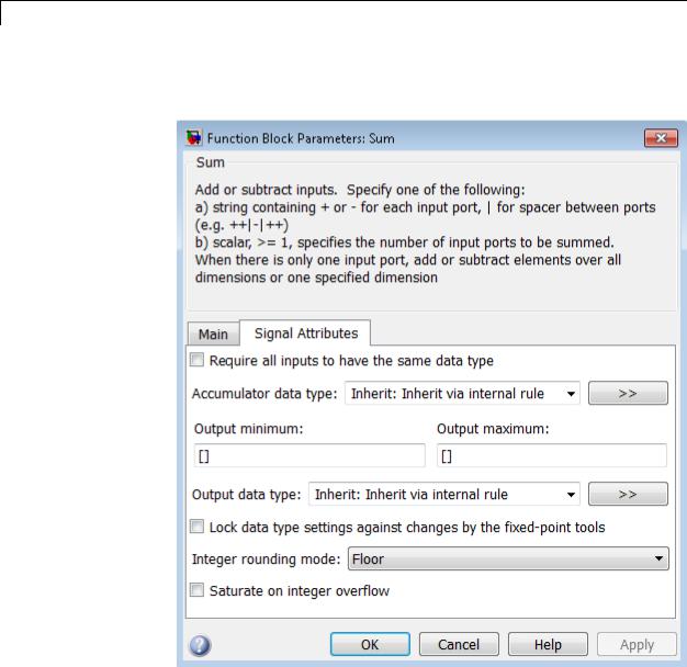
Sum, Add, Subtract, Sum of Elements
The Signal Attributes pane of the Sum block dialog box appears as follows:
2-1664

Sum, Add, Subtract, Sum of Elements
Show data type assistant
Display the Data Type Assistant.
Settings
The Data Type Assistant helps you set the Output data type parameter.
For more information, see “Specify Block Output Data Types”.
Command-Line Information
See “Block-Specific Parameters” on page 8-109 for the command-line information.
2-1665

Sum, Add, Subtract, Sum of Elements
Icon shape
Designate the icon shape of the block.
Settings
Default: round
rectangular
Designate the icon shape of the block as rectangular.
round
Designate the icon shape of the block as round.
Command-Line Information
See “Block-Specific Parameters” on page 8-109 for the command-line information.
2-1666

Sum, Add, Subtract, Sum of Elements
List of signs
Enter plus (+) and minus (-) characters.
Settings
Default: |++
•Addition is the default operation, so if you only want to add the inputs, enter the number of input ports.
•For a single vector input, “+” or “-” will collapse the vector using the specified operation.
•Enter as many plus (+) and minus (-) characters as there are inputs.
Tips
You can manipulate the positions of the input ports on the block by inserting spacers (|) between the signs in the List of signs parameter. For example, “++|--” creates an extra space between the second and third input ports.
Dependencies
Entering only one element enables the Sum over parameter.
Command-Line Information
See “Block-Specific Parameters” on page 8-109 for the command-line information.
2-1667

Sum, Add, Subtract, Sum of Elements
Sum over
Select dimension over which to perform the sum over operation.
Settings
Default: All dimensions
All dimensions
Sum all input elements, yielding a scalar.
Specified dimension
Display the Dimension parameter, where you specify the dimension over which to perform the operation.
Dependencies
Selecting Specified dimension enables the Dimension parameter. List of signs (when it has only one element) enables this parameter.
Command-Line Information
See “Block-Specific Parameters” on page 8-109 for the command-line information.
2-1668

Sum, Add, Subtract, Sum of Elements
Dimension
Specify the dimension over which to perform the operation.
Settings
Default: 1
The block follows the same summation rules as the MATLAB sum function.
Suppose that you have a 2-by-3 matrix U.
• Setting Dimension to 1 results in the output Y being computed as:
Y = ∑2i=1U(i, j)
• Setting Dimension to 2 results in the output Y being computed as:
Y = ∑3j=1U(i, j)
If the specified dimension is greater than the dimension of the input, an error message appears.
Dependencies
Setting Sum over to Specified dimension enables this parameter.
Command-Line Information
See “Block-Specific Parameters” on page 8-109 for the command-line information.
2-1669

Sum, Add, Subtract, Sum of Elements
Sample time (-1 for inherited)
Enter the discrete interval between sample time hits or specify another appropriate sample time such as continuous or inherited.
Settings
Default: -1
By default, the block inherits its sample time based upon the context of the block within the model. To set a different sample time, enter a valid sample time based upon the table in “Types of Sample Time”.
See also “Specify Sample Time” in the online documentation for more information.
Command-Line Information
See “Block-Specific Parameters” on page 8-109 for the command-line information.
2-1670

Sum, Add, Subtract, Sum of Elements
Require all inputs to have the same data type
Require that all inputs have the same data type.
Settings
Default: Off
 On
On
Require that all inputs have the same data type.
 Off
Off
Do not require that all inputs have the same data type.
Command-Line Information
See “Block-Specific Parameters” on page 8-109 for the command-line information.
2-1671

Sum, Add, Subtract, Sum of Elements
Lock data type settings against changes by the fixed-point tools
Select to lock data type settings of this block against changes by the Fixed-Point Tool and the Fixed-Point Advisor.
Settings
Default: Off
 On
On
Locks all data type settings for this block.
 Off
Off
Allows the Fixed-Point Tool and the Fixed-Point Advisor to change data type settings for this block.
Command-Line Information
See “Block-Specific Parameters” on page 8-109 for the command-line information.
2-1672
Sum, Add, Subtract, Sum of Elements
Integer rounding mode
Specify the rounding mode for fixed-point operations.
Settings
Default: Floor
Ceiling
Rounds both positive and negative numbers toward positive infinity. Equivalent to the MATLAB ceil function.
Convergent
Rounds number to the nearest representable value. If a tie occurs, rounds to the nearest even integer. Equivalent to the Fixed-Point Toolbox convergent function.
Floor
Rounds both positive and negative numbers toward negative infinity. Equivalent to the MATLAB floor function.
Nearest
Rounds number to the nearest representable value. If a tie occurs, rounds toward positive infinity. Equivalent to the Fixed-Point Toolbox nearest function.
Round
Rounds number to the nearest representable value. If a tie occurs, rounds positive numbers toward positive infinity and rounds negative numbers toward negative infinity. Equivalent to the Fixed-Point Toolbox round function.
Simplest
Automatically chooses between round toward floor and round toward zero to generate rounding code that is as efficient as possible.
Zero
Rounds number toward zero. Equivalent to the MATLAB fix function.
2-1673

Sum, Add, Subtract, Sum of Elements
Command-Line Information
See “Block-Specific Parameters” on page 8-109 for the command-line information.
See Also
For more information, see “Rounding” in the Simulink Fixed Point documentation.
2-1674

Sum, Add, Subtract, Sum of Elements
Saturate on integer overflow
Specify whether overflows saturate.
Settings
Default: Off
 On
On
Overflows saturate to either the minimum or maximum value that the data type can represent.
For example, an overflow associated with a signed 8-bit integer can saturate to -128 or 127.
 Off
Off
Overflows wrap to the appropriate value that is representable by the data type.
For example, the number 130 does not fit in a signed 8-bit integer and wraps to -126.
Tips
•Consider selecting this check box when your model has possible overflow and you want explicit saturation protection in the generated code.
•Consider clearing this check box when you want to optimize efficiency of your generated code.
Clearing this check box also helps you avoid overspecifying how a block handles out-of-range signals. For more information, see “Checking for Signal Range Errors”.
•When you select this check box, saturation applies to every internal operation on the block, not just the output or result.
•In general, the code generation process can detect when overflow is not possible. In this case, the code generator does not produce saturation code.
2-1675

Sum, Add, Subtract, Sum of Elements
Command-Line Information
See “Block-Specific Parameters” on page 8-109 for the command-line information.
2-1676

Sum, Add, Subtract, Sum of Elements
Accumulator data type
Specify the accumulator data type.
Settings
Default: Inherit: Inherit via internal rule
Inherit: Inherit via internal rule
Use internal rule to determine accumulator data type.
Inherit: Same as first input
Use data type of first input signal.
double
Accumulator data type is double.
single
Accumulator data type is single.
int8
Accumulator data type is int8.
uint8
Accumulator data type is uint8.
int16
Accumulator data type is int16.
uint16
Accumulator data type is uint16.
int32
Accumulator data type is int32.
uint32
Accumulator data type is uint32.
fixdt(1,16,0)
Accumulator data type is fixed point fixdt(1,16,0).
fixdt(1,16,2^0,0)
Accumulator data type is fixed point fixdt(1,16,2^0,0).
2-1677

Sum, Add, Subtract, Sum of Elements
<data type expression>
The name of a data type object, for example
Simulink.NumericType
Command-Line Information
See “Block-Specific Parameters” on page 8-109 for the command-line information.
See Also
For more information, see “Specify Data Types Using Data Type Assistant”.
2-1678

Sum, Add, Subtract, Sum of Elements
Mode
Select the category of accumulator data to specify
Settings
Default: Inherit
Inherit
Specifies inheritance rules for data types. Selecting Inherit enables a list of possible values:
•Inherit via internal rule (default)
•Same as first input
Built in
Specifies built-in data types. Selecting Built in enables a list of possible values:
•double (default)
•single
•int8
•uint8
•int16
•uint16
•int32
•uint32
Fixed point
Specifies fixed-point data types.
Expression
Specifies expressions that evaluate to data types. Selecting Expression enables you to enter an expression.
Dependency
Clicking the Show data type assistant button for the accumulator data type enables this parameter.
2-1679

Sum, Add, Subtract, Sum of Elements
Command-Line Information
See “Block-Specific Parameters” on page 8-109 for the command-line information.
See Also
See “Specify Data Types Using Data Type Assistant”.
2-1680

Sum, Add, Subtract, Sum of Elements
Data type override
Specify data type override mode for this signal.
Settings
Default: Inherit
Inherit
Inherits the data type override setting from its context, that is, from the block, Simulink.Signal object or Stateflow chart in Simulink that is using the signal.
Off
Ignores the data type override setting of its context and uses the fixed-point data type specified for the signal.
Tip
The ability to turn off data type override for an individual data type provides greater control over the data types in your model when you apply data type override. For example, you can use this option to ensure that data types meet the requirements of downstream blocks regardless of the data type override setting.
Dependency
This parameter appears only when the Mode is Built in or Fixed point.
2-1681

Sum, Add, Subtract, Sum of Elements
Signedness
Specify whether you want the fixed-point data to be signed or unsigned.
Settings
Default: Signed
Signed
Specify the fixed-point data to be signed.
Unsigned
Specify the fixed-point data to be unsigned.
Dependencies
Selecting Mode > Fixed point for the accumulator data type enables this parameter.
Command-Line Information
See “Block-Specific Parameters” on page 8-109 for the command-line information.
See Also
See “Specifying a Fixed-Point Data Type” for more information.
2-1682
Sum, Add, Subtract, Sum of Elements
Word length
Specify the bit size of the word that will hold the quantized integer.
Settings
Default: 16
Minimum: 0
Maximum: 32
Large word sizes represent large values with greater precision than small word sizes.
Dependencies
Selecting Mode > Fixed point for the accumulator data type enables this parameter.
Command-Line Information
See “Block-Specific Parameters” on page 8-109 for the command-line information.
See Also
See “Specifying a Fixed-Point Data Type” for more information.
2-1683

Sum, Add, Subtract, Sum of Elements
Scaling
Specify the method for scaling your fixed-point data to avoid overflow conditions and minimize quantization errors.
Settings
Default: Binary point
Binary point
Specify binary point location.
Slope and bias
Enter slope and bias.
Dependencies
Selecting Mode > Fixed point for the accumulator data type enables this parameter.
Selecting Binary point enables:
• Fraction length
Selecting Slope and bias enables:
•Slope
•Bias
Command-Line Information
See “Block-Specific Parameters” on page 8-109 for the command-line information.
See Also
See “Specifying a Fixed-Point Data Type” for more information.
2-1684

Sum, Add, Subtract, Sum of Elements
Fraction length
Specify fraction length for fixed-point data type.
Settings
Default: 0
Binary points can be positive or negative integers.
Dependencies
Selecting Scaling > Binary point for the accumulator data type enables this parameter.
Command-Line Information
See “Block-Specific Parameters” on page 8-109 for the command-line information.
See Also
See “Specifying a Fixed-Point Data Type” for more information.
2-1685

Sum, Add, Subtract, Sum of Elements
Slope
Specify slope for the fixed-point data type.
Settings
Default: 2^0
Specify any positive real number.
Dependencies
Selecting Scaling > Slope and bias for the accumulator data type enables this parameter.
Command-Line Information
See “Block-Specific Parameters” on page 8-109 for the command-line information.
See Also
See “Specifying a Fixed-Point Data Type” for more information.
2-1686

Sum, Add, Subtract, Sum of Elements
Bias
Specify bias for the fixed-point data type.
Settings
Default: 0
Specify any real number.
Dependencies
Selecting Scaling > Slope and bias for the accumulator data type enables this parameter.
Command-Line Information
See “Block-Specific Parameters” on page 8-109 for the command-line information.
See Also
See “Specifying a Fixed-Point Data Type” for more information.
2-1687

Sum, Add, Subtract, Sum of Elements
Output minimum
Specify the minimum value that the block should output.
Settings
Default: [] (unspecified)
This number must be a finite real double scalar value.
Note If you specify a bus object as the data type for this block, do not set the minimum value for bus data on the block. Simulink ignores this setting. Instead, set the minimum values for bus elements of the bus object specified as the data type. For information on the Minimum property of a bus element, see Simulink.BusElement.
Simulink uses the minimum to perform:
•Parameter range checking (see “Check Parameter Values”) for some blocks
•Simulation range checking (see “Signal Ranges”)
•Automatic scaling of fixed-point data types
Command-Line Information
See “Block-Specific Parameters” on page 8-109 for the command-line information.
2-1688

Sum, Add, Subtract, Sum of Elements
Output maximum
Specify the maximum value that the block should output.
Settings
Default: [] (unspecified)
This number must be a finite real double scalar value.
Note If you specify a bus object as the data type for this block, do not set the maximum value for bus data on the block. Simulink ignores this setting. Instead, set the maximum values for bus elements of the bus object specified as the data type. For information on the Maximum property of a bus element, see Simulink.BusElement.
Simulink uses the maximum value to perform:
•Parameter range checking (see “Check Parameter Values”) for some blocks
•Simulation range checking (see “Signal Ranges”)
•Automatic scaling of fixed-point data types
Command-Line Information
See “Block-Specific Parameters” on page 8-109 for the command-line information.
2-1689

Sum, Add, Subtract, Sum of Elements
Output data type
Specify the output data type.
Settings
Default: Inherit: Inherit via internal rule
Inherit: Inherit via internal rule
Simulink chooses a combination of output scaling and data type that requires the smallest amount of memory consistent with accommodating the calculated output range and maintaining the output precision of the block and with the word size of the targeted hardware implementation specified for the model. If the
Device type parameter on the Hardware Implementation configuration parameters pane is set to ASIC/FPGA, Simulink software chooses the output data type without regard to hardware constraints. Otherwise, Simulink software chooses the smallest available hardware data type capable of meeting the range and precision constraints. For example, if the block multiplies an input of type int8 by a gain of int16 and ASIC/FPGA is specified as the targeted hardware type, the output data type is sfix24. If Unspecified (assume 32-bit Generic), i.e., a generic 32-bit microprocessor, is specified as the target hardware, the output data type is int32. If none of the word lengths provided by
the target microprocessor can accommodate the output range, Simulink software displays an error message in the Simulation Diagnostics Viewer.
Inherit: Inherit via back propagation
Use data type of the driving block.
Inherit: Same as first input
Use data type of first input signal.
Inherit: Same as accumulator
Output data type is the same as accumulator data type.
double
Output data type is double.
2-1690

Sum, Add, Subtract, Sum of Elements
single
Output data type is single.
int8
Output data type is int8.
uint8
Output data type is uint8.
int16
Output data type is int16.
uint16
Output data type is uint16.
int32
Output data type is int32.
uint32
Output data type is uint32.
fixdt(1,16,0)
Output data type is fixed point fixdt(1,16,0).
fixdt(1,16,2^0,0)
Output data type is fixed point fixdt(1,16,2^0,0).
<data type expression>
Use a data type object, for example, Simulink.NumericType.
Command-Line Information
See “Block-Specific Parameters” on page 8-109 for the command-line information.
See Also
For more information, see “Specify Block Output Data Types”.
2-1691

Sum, Add, Subtract, Sum of Elements
Mode
Select the category of data to specify.
Settings
Default: Inherit
Inherit
Inheritance rules for data types. Selecting Inherit enables a second menu/text box to the right. Select one of the following choices:
•Inherit via internal rule (default)
•Inherit via back propagation
•Same as first input
•Same as accumulator
Built in
Built-in data types. Selecting Built in enables a second menu/text box to the right. Select one of the following choices:
•double (default)
•single
•int8
•uint8
•int16
•uint16
•int32
•uint32
Fixed point
Fixed-point data types.
2-1692
Sum, Add, Subtract, Sum of Elements
Expression
Expressions that evaluate to data types. Selecting Expression enables a second menu/text box to the right, where you can enter the expression.
Dependency
Clicking the Show data type assistant button enables this parameter.
Command-Line Information
See “Block-Specific Parameters” on page 8-109 for the command-line information.
See Also
See “Specify Data Types Using Data Type Assistant”.
2-1693

Sum, Add, Subtract, Sum of Elements
Signedness
Specify whether you want the fixed-point data as signed or unsigned.
Settings
Default: Signed
Signed
Specify the fixed-point data as signed.
Unsigned
Specify the fixed-point data as unsigned.
Dependencies
Selecting Mode > Fixed point enables this parameter.
Command-Line Information
See “Block-Specific Parameters” on page 8-109 for the command-line information.
See Also
For more information, see “Specifying a Fixed-Point Data Type”.
2-1694

Sum, Add, Subtract, Sum of Elements
Word length
Specify the bit size of the word that holds the quantized integer.
Settings
Default: 16
Minimum: 0
Maximum: 32
Dependencies
Selecting Mode > Fixed point enables this parameter.
Command-Line Information
See “Block-Specific Parameters” on page 8-109 for the command-line information.
See Also
For more information, see “Specifying a Fixed-Point Data Type”.
2-1695

Sum, Add, Subtract, Sum of Elements
Scaling
Specify the method for scaling your fixed-point data to avoid overflow conditions and minimize quantization errors.
Settings
Default: Binary point
Binary point
Specify binary point location.
Slope and bias
Enter slope and bias.
Dependencies
Selecting Mode > Fixed point enables this parameter. Selecting Binary point enables:
•Fraction length
•Calculate Best-Precision Scaling
Selecting Slope and bias enables:
•Slope
•Bias
•Calculate Best-Precision Scaling
Command-Line Information
See “Block-Specific Parameters” on page 8-109 for the command-line information.
See Also
See “Specifying a Fixed-Point Data Type”.
2-1696

Sum, Add, Subtract, Sum of Elements
Fraction length
Specify fraction length for fixed-point data type.
Settings
Default: 0
Binary points can be positive or negative integers.
Dependencies
Selecting Scaling > Binary point enables this parameter.
Command-Line Information
See “Block-Specific Parameters” on page 8-109 for the command-line information.
See Also
For more information, see “Specifying a Fixed-Point Data Type”.
2-1697

Sum, Add, Subtract, Sum of Elements
Slope
Specify slope for the fixed-point data type.
Settings
Default: 2^0
Specify any positive real number.
Dependencies
Selecting Scaling > Slope and bias enables this parameter.
Command-Line Information
See “Block-Specific Parameters” on page 8-109 for the command-line information.
See Also
For more information, see “Specifying a Fixed-Point Data Type”.
Bias
Specify bias for the fixed-point data type.
Settings
Default: 0
Specify any real number.
Dependencies
Selecting Scaling > Slope and bias enables this parameter.
Command-Line Information
See “Block-Specific Parameters” on page 8-109 for the command-line information.
See Also
For more information, see “Specifying a Fixed-Point Data Type”.
Examples How the Sum Block Reorders Inputs
If you use - on the first input port, the Sum block reorders the inputs so that, if possible, the first input uses a + operation. For example, in the expression output = -a-b+c, the Sum block reorders the inputs
2-1698
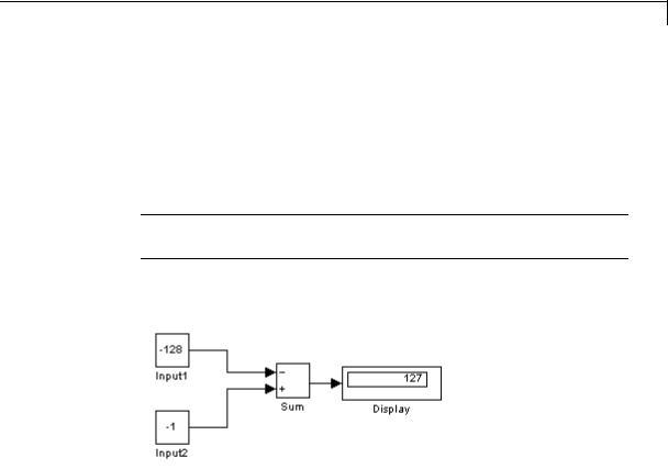
Sum, Add, Subtract, Sum of Elements
so that output = c-a-b. To initialize the accumulator, the Sum block uses the first + input port.
The block avoids performing a unary minus operation on the first operand a because doing so can change the value of a for fixed-point data types. In that case, the output value differs from the result of accumulating the values for a, b, and c.
Tip To explicitly specify a unary minus operation for output = -a-b+c, you can use the Unary Minus block in the Math Operations library.
Suppose that you have the following model:
The following block parameters apply:
•Both Constant blocks, Input1 and Input 2, use int8 for the Output data type.
•The Sum block uses int8 for both Accumulator data type and
Output data type.
•The Sum block has Saturate on integer overflow turned on.
The Sum block reorders the inputs so that the following operations occur and you get the ideal result of 127.
2-1699

Sum, Add, Subtract, Sum of Elements
|
Step |
Block Operation |
|
|
|
1 |
Reorders inputs from ( Input1 + Input2) to (Input2 |
|
|
|
|
Input1). |
|
|
|
2 |
Initializes the accumulator by using the first + input port: |
|
|
|
|
Accumulator = int8(-1) = -1 |
|
|
|
3 |
Continues to accumulate values: |
|
|
|
|
Accumulator = Accumulator |
int8(-128) = 127 |
|
|
4 |
Calculates the block output: |
|
|
|
|
Output = int8(127) = 127 |
|
|
|
|
|
|
|
If the Sum block does not reorder the inputs, the following operations occur instead and you get the nonideal result of 126.
Step Block Operation
1Initializes the accumulator by using the first input port:
Accumulator = int8(-(-128)) = 127
Because saturation is on, the initial value of the accumulator saturates at 127 and does not wrap.
2Continues to accumulate values:
Accumulator = Accumulator + int8(-1) = 126
3Calculates the block output:
Output = int8(126) = 126
Characteristics |
Direct Feedthrough |
Yes |
|
Sample Time |
Specified in the Sample time |
|
|
parameter |
|
Scalar Expansion |
Yes |
|
|
|
2-1700

Sum, Add, Subtract, Sum of Elements
States |
0 |
Dimensionalized |
Yes |
Multidimensionalized |
Yes, only along the specified dimension |
Zero-Crossing Detection |
No |
|
|
2-1701

Switch
Purpose |
Switch output between first input and third input based on value of |
|
second input |
Library |
Signal Routing |
Description |
Types of Block Inputs |
|
The Switch block passes through the first input or the third input based |
|
on the value of the second input. The first and third inputs are called |
|
data inputs. The second input is called the control input. Specify the |
|
condition under which the block passes the first input by using the |
|
Criteria for passing first input and Threshold parameters. |
|
To immediately back propagate a known output data type to the |
|
first and third input ports, set the Output data type parameter to |
|
Inherit: Inherit via internal rule and select the Require all |
|
data port inputs to have the same data type check box. |
|
Limitations on Data Inputs |
|
The sizes of the two data inputs can be different if you select Allow |
|
different data input sizes on the block dialog box. However, this |
|
block does not support variable-size input signals. Therefore, the size of |
|
each input cannot change during simulation. |
|
If the data inputs to the Switch block are buses, the element names of |
|
both buses must be the same. Using the same element names ensures |
|
that the output bus has the same element names no matter which |
|
input bus the block selects. To ensure that your model meets this |
|
requirement, use a bus object to define the buses and set the Element |
|
name mismatch diagnostic to error. See “Connectivity Diagnostics |
|
Overview” for more information. |
|
Block Icon Appearance |
|
The block icon helps you identify Criteria for passing first input and |
|
Threshold without having to open the block dialog box. |
|
For information about port order for various block orientations, see |
|
“How to Rotate a Block” in the Simulink documentation. |
2-1702
Switch
Data Type
Support
Block Behavior for Boolean Control Input
When the control input is a Boolean signal, use one of these combinations of criteria and threshold value:
•u2 >= Threshold, where the threshold value equals 1
•u2 > Threshold, where the threshold value equals 0
•u2 ~=0
Otherwise, the Switch block ignores the threshold and uses the Boolean input for signal routing. For a control input of 1, the block passes the first input, and for a control input of 0, the block passes the third input. In this case, the block icon changes after compile time and uses T and F to label the first and third inputs, respectively.
The control input can be of any data type that Simulink supports, including fixed-point and enumerated types. The control input cannot be complex. If the control input is enumerated, the Threshold parameter must be a value of the same enumerated type.
The data inputs can be of any data type that Simulink supports. If either data input is of an enumerated type, the other must be of the same enumerated type.
When the output is of enumerated type, both data inputs should use the same enumerated type as the output.
For more information, see “Data Types Supported by Simulink” in the Simulink documentation.
2-1703
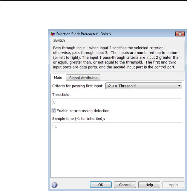
Switch
Parameters The Main pane of the Switch block dialog box appears as follows:
and Dialog Box
2-1704

Switch
The Signal Attributes pane of the Switch block dialog box appears as follows:
2-1705

Switch
•“Criteria for passing first input” on page 2-1707
•“Threshold” on page 2-1709
•“Enable zero-crossing detection” on page 2-1710
•“Sample time (-1 for inherited)” on page 2-1938
•“Require all data port inputs to have the same data type” on page 2-1712
•“Lock output data type setting against changes by the fixed-point tools” on page 2-1713
•“Integer rounding mode” on page 2-1714
•“Saturate on integer overflow” on page 2-1716
•“Allow different data input sizes” on page 2-1718
•“Output minimum” on page 2-1719
•“Output maximum” on page 2-1720
•“Output data type” on page 2-1721
•“Mode” on page 2-1723
•“Data type override” on page 2-1892
•“Signedness” on page 2-1893
•“Word length” on page 2-1896
•“Scaling” on page 2-1728
•“Fraction length” on page 2-1897
•“Slope” on page 2-1898
•“Bias” on page 2-1898
2-1706

Switch
Criteria for passing first input
Select the condition under which the block passes the first input. If the control input meets the condition set in the Criteria for passing first input parameter, the block passes the first input. Otherwise, the block passes the third input.
Settings
Default: u2 >= Threshold
u2 >= Threshold
Checks whether the control input is greater than or equal to the threshold value.
u2 > Threshold
Checks whether the control input is greater than the threshold value.
u2 ~=0
Checks whether the control input is nonzero.
Note The Switch block does not support u2 ~=0 mode for enumerated data types.
Tip
When the control input is a Boolean signal, use one of these combinations of condition and threshold value:
•u2 >= Threshold, where the threshold value equals 1
•u2 > Threshold, where the threshold value equals 0
•u2 ~=0
Otherwise, the Switch block ignores threshold values and uses the Boolean value for signal routing. For a value of 1, the block passes the first input, and for a value of 0, the block passes the third input.
2-1707

Switch
A warning message that describes this behavior also appears in the MATLAB Command Window.
Dependencies
Selecting u2 ~=0 disables the Threshold parameter.
Command-Line Information
See “Block-Specific Parameters” on page 8-109 for the command-line information.
2-1708

Switch
Threshold
Assign the switch threshold that determines which input the block passes to the output.
Settings
Default: 0
Minimum: value from the Output minimum parameter Maximum: value from the Output maximum parameter
Tip
To specify a nonscalar threshold, use brackets. For example, the following entries are valid:
•[1 4 8 12]
•[MyColors.Red, MyColors.Blue]
Dependencies
Setting Criteria for passing first input to u2 ~=0 disables this parameter.
Command-Line Information
See “Block-Specific Parameters” on page 8-109 for the command-line information.
2-1709

Switch
Enable zero-crossing detection
Select to enable zero-crossing detection. For more information, see “Zero-Crossing Detection” in the Simulink documentation.
Settings
Default: On
 On
On
Enable zero-crossing detection.
 Off
Off
Do not enable zero-crossing detection.
Command-Line Information
See “Block-Specific Parameters” on page 8-109 for the command-line information.
2-1710

Switch
Sample time (-1 for inherited)
Enter the discrete interval between sample time hits or specify another appropriate sample time such as continuous or inherited.
Settings
Default: -1
By default, the block inherits its sample time based upon the context of the block within the model. To set a different sample time, enter a valid sample time based upon the table in “Types of Sample Time”.
See also “Specify Sample Time” in the online documentation for more information.
Command-Line Information
See “Block-Specific Parameters” on page 8-109 for the command-line information.
2-1711

Switch
Require all data port inputs to have the same data type
Require all data inputs to have the same data type.
Settings
Default: Off
 On
On
Requires all data inputs to have the same data type.
 Off
Off
Does not require all data inputs to have the same data type.
Command-Line Information
See “Block-Specific Parameters” on page 8-109 for the command-line information.
2-1712
Switch
Lock output data type setting against changes by the fixed-point tools
Select to lock the output data type setting of this block against changes by the Fixed-Point Tool and the Fixed-Point Advisor.
Settings
Default: Off
 On
On
Locks the output data type setting for this block.
 Off
Off
Allows the Fixed-Point Tool and the Fixed-Point Advisor to change the output data type setting for this block.
Command-Line Information
See “Block-Specific Parameters” on page 8-109 for the command-line information.
See Also
For more information, see “Use Lock Output Data Type Setting”.
2-1713

Switch
Integer rounding mode
Specify the rounding mode for fixed-point operations.
Settings
Default: Floor
Ceiling
Rounds both positive and negative numbers toward positive infinity. Equivalent to the MATLAB ceil function.
Convergent
Rounds number to the nearest representable value. If a tie occurs, rounds to the nearest even integer. Equivalent to the Fixed-Point Toolbox convergent function.
Floor
Rounds both positive and negative numbers toward negative infinity. Equivalent to the MATLAB floor function.
Nearest
Rounds number to the nearest representable value. If a tie occurs, rounds toward positive infinity. Equivalent to the Fixed-Point Toolbox nearest function.
Round
Rounds number to the nearest representable value. If a tie occurs, rounds positive numbers toward positive infinity and rounds negative numbers toward negative infinity. Equivalent to the Fixed-Point Toolbox round function.
Simplest
Automatically chooses between round toward floor and round toward zero to generate rounding code that is as efficient as possible.
Zero
Rounds number toward zero. Equivalent to the MATLAB fix function.
2-1714

Switch
Command-Line Information
See “Block-Specific Parameters” on page 8-109 for the command-line information.
See Also
For more information, see “Rounding” in the Simulink Fixed Point documentation.
2-1715

Switch
Saturate on integer overflow
Specify whether overflows saturate.
Settings
Default: Off
 On
On
Overflows saturate to either the minimum or maximum value that the data type can represent.
For example, an overflow associated with a signed 8-bit integer can saturate to -128 or 127.
 Off
Off
Overflows wrap to the appropriate value that is representable by the data type.
For example, the number 130 does not fit in a signed 8-bit integer and wraps to -126.
Tips
•Consider selecting this check box when your model has possible overflow and you want explicit saturation protection in the generated code.
•Consider clearing this check box when you want to optimize efficiency of your generated code.
Clearing this check box also helps you avoid overspecifying how a block handles out-of-range signals. For more information, see “Checking for Signal Range Errors”.
•When you select this check box, saturation applies to every internal operation on the block, not just the output or result.
•In general, the code generation process can detect when overflow is not possible. In this case, the code generator does not produce saturation code.
2-1716

Switch
Command-Line Information
See “Block-Specific Parameters” on page 8-109 for the command-line information.
2-1717