


Version 1.00a 19-Apr-2006 |
MIPI Alliance Standard for DSI |
|||||||||||||||
|
|
|
|
|
|
|
|
|
|
|
|
|
|
|
|
|
|
|
|
|
|
|
|
|
|
|
|
|
|
|
|
|
|
|
|
|
|
|
|
|
|
|
|
|
|
|
|
|
|
|
|
|
|
|
|
|
|
|
|
|
|
|
|
|
|
|
|
|
|
|
|
|
|
|
|
|
|
|
|
|
|
|
|
|
|
|
|
|
|
|
|
|
|
|
|
|
|
|
|
|
|
|
|
|
|
|
|
|
|
|
|
|
|
|
|
|
|
|
|
|
|
|
|
|
|
|
|
|
|
|
|
|
|
|
|
|
|
|
|
|
|
|
|
|
|
|
|
|
|
|
|
|
|
|
|
|
|
|
|
|
|
|
|
|
|
|
|
|
|
|
|
|
|
|
|
|
|
|
|
|
|
|
|
|
|
|
|
|
|
|
|
|
|
|
|
|
|
|
|
|
|
|
|
|
|
|
|
|
|
|
|
|
|
|
|
|
|
|
|
|
|
|
|
|
|
|
|
|
|
|
|
|
|
|
|
|
|
|
|
|
|
|
|
|
|
|
|
|
|
|
|
|
|
|
554 |
|
555 |
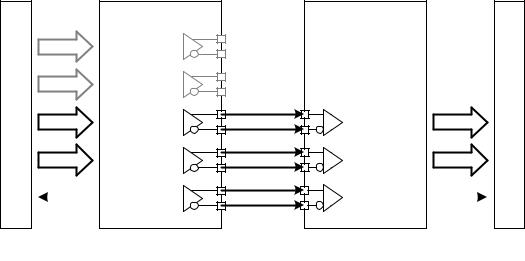
Figure 5 Lane Merger Conceptual Overview |
556The Lane Distributor takes a HS transmission of arbitrary byte length, buffers N bytes, where N is the
557number of Lanes implemented in the interface, and sends groups of N bytes in parallel across the N Lanes.
558Before sending data, all Lanes perform the SoT sequence in parallel to indicate to their corresponding
559receiving units that the first byte of a packet is beginning. After SoT, the Lanes send groups of N bytes
560from the first packet in parallel, following a round-robin process. For example, with a two Lane system,
561byte 0 of the packet goes to Lane 0, byte 1 goes to Lane 1, byte 2 to Lane 0, byte 3 to Lane 1 and so on.
5626.1 Multi-Lane Interoperability and Lane-number Mismatch
563The number of Lanes used shall be a static parameter. It shall be fixed at the time of system design or initial
564configuration and may not change dynamically. Typically, the peripheral’s bandwidth requirement and its
565corresponding Lane configuration establishes the number of Lanes used in a system.
566The host processor shall be configured to support the same number of Lanes required by the peripheral.
567Specifically, a host processor with N-Lane capability (N > 1) shall be capable of operation using fewer
568Lanes, to ensure interoperability with peripherals having M Lanes, where N > M.
Copyright © 2005-2006 MIPI Alliance, Inc. All rights reserved. MIPI Alliance Member Confidential.
24
Version 1.00a 19-Apr-2006 |
|
|
|
|
|
MIPI Alliance Standard for DSI |
|||||||||
|
|
|
|
|
|
|
|
|
|
|
|
|
|
|
|
|
|
|
|
|
|
|
|
|
|
|
|
|
|
|
|
|
|
|
|
|
|
|
|
|
|
|
|
|
|
|
|
|
|
|
|
|
|
|
|
|
|
|
|
|
|
|
|
|
|
|
|
|
|
|
|
|
|
|
|
|
|
|
|
|
|
|
|
|
|
|
|
|
|
|
|
|
|
|
|
|
|
|
|
|
|
|
|
|
|
|
|
|
|
|
|
|
|
|
|
|
|
|
|
|
|
|
|
|
|
|
|
|
|
|
|
|
|
|
|
|
|
|
|
|
|
|
|
|
|
|
|
|
|
|
|
|
|
|
|
|
|
|
|
|
|
|
|
|
|
|
|
|
|
|
|
|
|
|
|
|
|
|
|
|
|
|
|
|
|
|
|
|
|
|
|
|
|
|
|
|
|
|
|
|
|
|
|
|
|
|
|
|
|
|
|
|
|
|
|
|
|
|
|
|
|
|
|
|
|
|
|
|
|
|
|
|
|
|
|
|
|
|
|
|
|
|
|
|
|
|
|
|
|
|
|
|
|
|
|
|
|
|
|
|
|
|
|
|
|
|
|
|
|
|
|
|
|
|
|
|
|
|
|
|
|
|
|
|
|
|
|
|
|
|
|
|
|
|
|
|
|
|
|
|
|
|
|
|
|
|
|
|
|
|
|
|
|
|
|
|
|
|
|
|
|
|
|
|
|
|
|
|
|
|
|
|
|
|
|
|
|
|
|
|
|
|
|
|
|
|
|
|
|
|
|
|
|
|
|
|
|
|
|
|
|
|
|
|
|
|
|
|
|
|
|
|
|
|
|
|
|
|
|
|
|
|
|
|
|
|
|
|
|
|
|
|
|
|
|
|
|
|
|
|
|
|
|
|
|
|
|
|
|
|
|
|
|
|
|
|
|
|
|
|
|
|
|
|
|
|
|
|
|
|
|
|
|
|
|
|
|
|
|
|
|
|
|
|
|
|
|
|
|
|
|
|
|
|
|
|
|
|
|
|
|
|
|
|
|
|
|
|
|
|
|
|
|
|
|
|
|
|
|
569 |
|
570 |
Figure 6 Four-Lane Transmitter with Two-Lane Receiver Example |
5716.1.1 Clock Considerations with Multi-Lane
572At EoT, the Protocol layer shall base its control of the common DSI Clock signal on the timing
573requirements for the last active Lane Module. If the Protocol layer puts the DSI Clock into LPS between
574HS transmissions to save power, it shall respect the timing requirement for DSI Clock relative to all serial
575data signals during the EoT sequence.
576Prior to SoT, timing requirements for DSI Clock startup relative to all serial data signals shall similarly be
577respected.
5786.1.2 Bi-directionality and Multi-Lane Capability
579 Peripherals typically do not have substantial bandwidth requirements for returning data to the host
580processor. To keep designs simple and improve interoperability, all DSI-compliant systems shall only use
581Lane 0 in LP Mode for returning data from a peripheral to the host processor.
5826.1.3 SoT and EoT in Multi-Lane Configurations
583Since a HS transmission is composed of an arbitrary number of bytes that may not be an integer multiple of
584the number of Lanes, some Lanes may run out of data before others. Therefore, the Lane Management
585layer, as it buffers up the final set of less-than-N bytes, de-asserts its “valid data” signal into all Lanes for
586which there is no further data.
587Although all Lanes start simultaneously with parallel SoTs, each Lane operates independently and may
588complete the HS transmission before the other Lanes, sending an EoT one cycle (byte) earlier.
589The N PHYs on the receiving end of the Link collect bytes in parallel and feed them into the Lane
590Management layer. The Lane Management layer reconstructs the original sequence of bytes in the
591transmission.
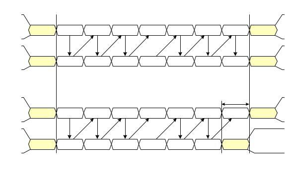
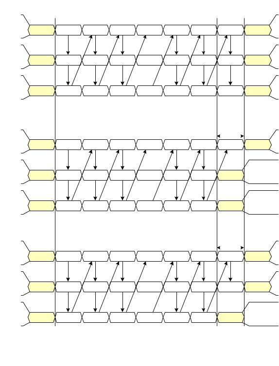
592Figure 7 and Figure 8 illustrate a variety of ways a HS transmission can terminate for different number of
593Lanes and packet lengths.
594Note the special case of a multi-Lane implementation, having N Lanes, which may occasionally send a
595short, HS transmission where the packet length is less than N. In this case, Lanes without data to transmit
596shall remain in LPS.
Copyright © 2005-2006 MIPI Alliance, Inc. All rights reserved. MIPI Alliance Member Confidential.
25
Version 1.00a 19-Apr-2006 |
MIPI Alliance Standard for DSI |
597 |
|
598 |
Figure 7 Two Lane HS Transmission Example |
Copyright © 2005-2006 MIPI Alliance, Inc. All rights reserved. MIPI Alliance Member Confidential.
26
Version 1.00a 19-Apr-2006 |
MIPI Alliance Standard for DSI |
||
|
|
|
|
|
|
|
|
599 |
|
600 |
Figure 8 Three Lane HS Transmission Example |
Copyright © 2005-2006 MIPI Alliance, Inc. All rights reserved. MIPI Alliance Member Confidential.
27