- •1 Overview
- •1.1 Scope
- •1.2 Purpose
- •2 Terminology (Informational)
- •2.1 Definitions
- •2.2 Abbreviations
- •2.3 Acronyms
- •3 References (Informational)
- •3.1 DBI and DBI-2 (Display Bus Interface Standards for Parallel Signaling)
- •3.2 DPI and DPI-2 (Display Pixel Interface Standards for Parallel Signaling)
- •3.3 DCS (Display Command Set)
- •3.4 CSI-2 (Camera Serial Interface 2)
- •3.5 D-PHY (MIPI Alliance Standard for Physical Layer)
- •4 DSI Introduction
- •4.1 DSI Layer Definitions
- •4.2 Command and Video Modes
- •4.2.1 Command Mode
- •4.2.2 Video Mode Operation
- •4.2.3 Virtual Channel Capability
- •5 DSI Physical Layer
- •5.1 Data Flow Control
- •5.2 Bidirectionality and Low Power Signaling Policy
- •5.3 Command Mode Interfaces
- •5.4 Video Mode Interfaces
- •5.5 Bidirectional Control Mechanism
- •5.6 Clock Management
- •5.6.1 Clock Requirements
- •5.6.2 Clock Power and Timing
- •6 Multi-Lane Distribution and Merging
- •6.1 Multi-Lane Interoperability and Lane-number Mismatch
- •6.1.1 Clock Considerations with Multi-Lane
- •6.1.2 Bi-directionality and Multi-Lane Capability
- •6.1.3 SoT and EoT in Multi-Lane Configurations
- •7 Low-Level Protocol Errors and Contention
- •7.1 Low-Level Protocol Errors
- •7.1.1 SoT Error
- •7.1.2 SoT Sync Error
- •7.1.3 EoT Sync Error
- •7.1.4 Escape Mode Entry Command Error
- •7.1.5 LP Transmission Sync Error
- •7.1.6 False Control Error
- •7.2 Contention Detection and Recovery
- •7.2.1 Contention Detection in LP Mode
- •7.2.2 Contention Recovery Using Timers
- •7.3 Additional Timers
- •7.3.1 Turnaround Acknowledge Timeout (TA_TO)
- •7.3.2 Peripheral Reset Timeout (PR_TO)
- •7.4 Acknowledge and Error Reporting Mechanism
- •8 DSI Protocol
- •8.1 Multiple Packets per Transmission
- •8.2 Packet Composition
- •8.3 Endian Policy
- •8.4 General Packet Structure
- •8.4.1 Long Packet Format
- •8.4.2 Short Packet Format
- •8.5 Common Packet Elements
- •8.5.1 Data Identifier Byte
- •8.5.2 Error Correction Code
- •8.6 Interleaved Data Streams
- •8.6.1 Interleaved Data Streams and Bi-directionality
- •8.7 Processor to Peripheral Direction (Processor-Sourced) Packet Data Types
- •8.8 Processor-to-Peripheral Transactions – Detailed Format Description
- •8.8.1 Sync Event (H Start, H End, V Start, V End), Data Type = xx 0001 (x1h)
- •8.8.2 Color Mode On Command, Data Type = 00 0010 (02h)
- •8.8.3 Color Mode Off Command, Data Type = 01 0010 (12h)
- •8.8.4 Shutdown Peripheral Command, Data Type = 10 0010 (22h)
- •8.8.5 Turn On Peripheral Command, Data Type = 11 0010 (32h)
- •8.8.6 Generic Short WRITE Packet, 0 to 7 Parameters, Data Type = xx x011 (x3h and xBh)
- •8.8.7 Generic READ Request, 0 to 7 Parameters, Data Type = xx x100 (x4h and xCh)
- •8.8.8 DCS Commands
- •8.8.9 Set Maximum Return Packet Size, Data Type = 11 0111 (37h)
- •8.8.10 Null Packet (Long), Data Type = 00 1001 (09h)
- •8.8.11 Blanking Packet (Long), Data Type = 01 1001 (19h)
- •8.8.12 Generic Non-Image Data (Long), Data Type = 10 1001 (29h)
- •8.8.13 Packed Pixel Stream, 16-bit Format, Long packet, Data Type 00 1110 (0Eh)
- •8.8.14 Packed Pixel Stream, 18-bit Format, Long packet, Data type = 01 1110 (1Eh)
- •8.8.15 Pixel Stream, 18-bit Format in Three Bytes, Long packet, Data Type = 10 1110 (2Eh)
- •8.8.16 Packed Pixel Stream, 24-bit Format, Long packet, Data Type = 11 1110 (3Eh)
- •8.8.17 DO NOT USE and Reserved Data Types
- •8.9 Peripheral-to-Processor (Reverse Direction) LP Transmissions
- •8.9.1 Packet Structure for Peripheral-to-Processor LP Transmissions
- •8.9.2 System Requirements for ECC and Checksum and Packet Format
- •8.9.3 Appropriate Responses to Commands and ACK Requests
- •8.9.4 Format of Acknowledge with Error Report and Read Response Data Types
- •8.9.5 Error-Reporting Format
- •8.10 Peripheral-to-Processor Transactions – Detailed Format Description
- •8.10.1 Acknowledge with Error Report, Data Type 00 0010 (02h)
- •8.10.2 Generic Short Read Response with Optional ECC, Data Type 01 0xxx (10h – 17h)
- •8.10.5 DCS Short Read Response with Optional ECC, Data Type 10 0xxx (20h – 27h)
- •8.10.6 Multiple-packet Transmission and Error Reporting
- •8.10.7 Clearing Error Bits
- •8.11 Video Mode Interface Timing
- •8.11.1 Traffic Sequences
- •8.11.2 Non-Burst Mode with Sync Pulses
- •8.11.3 Non-Burst Mode with Sync Events
- •8.11.4 Burst Mode
- •8.11.5 Parameters
- •8.12 TE Signaling in DSI
- •9 Error-Correcting Code (ECC) and Checksum
- •9.1 Hamming Code for Packet Header Error Detection/Correction
- •9.2 Hamming-modified Code for DSI
- •9.3 ECC Generation on the Transmitter and Byte-Padding
- •9.4 Applying ECC and Byte-Padding on the Receiver
- •9.5 Checksum Generation for Long Packet Payloads
- •10 Compliance, Interoperability, and Optional Capabilities
- •10.1 Display Resolutions
- •10.2 Pixel Formats
- •10.3 Number of Lanes
- •10.4 Maximum Lane Frequency
- •10.5 Bidirectional Communication
- •10.6 ECC and Checksum Capabilities
- •10.7 Display Architecture
- •10.8 Multiple Peripheral Support
- •A.1 PHY Detected Contention
- •A.1.1 Protocol Response to PHY Detected Faults
Version 1.00a 19-Apr-2006 |
MIPI Alliance Standard for DSI |
7738 DSI Protocol
774On the transmitter side of a DSI Link, parallel data, signal events, and commands are converted in the
775Protocol layer to packets, following the packet organization documented in this section. The Protocol layer
776appends packet-protocol information and headers, and then sends complete bytes through the Lane
777Management layer to the PHY. Packets are serialized by the PHY and sent across the serial Link. The
778receiver side of a DSI Link performs the converse of the transmitter side, decomposing the packet into
779parallel data, signal events and commands.
780If there are multiple Lanes, the Lane Management layer distributes bytes to separate PHYs, one PHY per
781Lane, as described in Section 6. Packet protocol and formats are independent of the number of Lanes used.
7828.1 Multiple Packets per Transmission
783In its simplest form, a transmission may contain one packet. If many packets are to be transmitted, the
784overhead of frequent switching between LPS and High-Speed Mode will severely limit bandwidth if
785packets are sent separately, e.g. one packet per transmission.
786 The DSI protocol permits multiple packets to be concatenated, which substantially boosts effective
787bandwidth. This is useful for events such as peripheral initialization, where many registers may be loaded
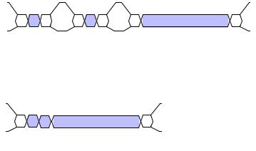
788with separate write commands at system startup. Figure 9 illustrates multiple packets being sent separately,
789and as concatenated packets in a single HS transmission.
790In HS Mode, time gaps between packets shall result in separate HS transmissions for each packet, with a
791SoT, LPS, and EoT between packets. This constraint does not apply to LP transmissions.
792 |
|
793 |
Figure 9 Multiple Packet HS Transmission Example |
7948.2 Packet Composition
795The first byte of the packet, the Data Identifier (DI), includes information specifying the length of the
796packet. For example, in Video Mode systems in a display application the logical unit for a packet may be
797one horizontal display line. Command Mode systems send commands and an associated set of parameters,
798with the number of parameters depending on the command type.
Copyright © 2005-2006 MIPI Alliance, Inc. All rights reserved. MIPI Alliance Member Confidential.
37