


|
Version 1.00a 19-Apr-2006 |
|
|
|
|
MIPI Alliance Standard for DSI |
|||||
|
|
|
|
|
|
|
|
|
|
|
|
|
Bit |
|
P7 |
P6 |
P5 |
P4 |
P3 |
P2 |
P1 |
P0 |
Hex |
|
58 |
|
1 |
1 |
0 |
0 |
0 |
0 |
0 |
1 |
0xC1 |
|
59 |
|
1 |
1 |
0 |
0 |
0 |
0 |
1 |
0 |
0xC2 |
|
60 |
|
1 |
1 |
0 |
0 |
0 |
1 |
0 |
0 |
0xC4 |
|
61 |
|
1 |
1 |
0 |
0 |
1 |
0 |
0 |
0 |
0xC8 |
|
62 |
|
1 |
1 |
0 |
1 |
0 |
0 |
0 |
0 |
0xD0 |
|
63 |
|
1 |
1 |
1 |
0 |
0 |
0 |
0 |
0 |
0xE0 |
1449 |
To derive parity byte P7, the “ones” in the P7 column define if the corresponding bit position Di (as noted |
||||||||||
1450 |
in the green column) is used in calculation of P7 parity bit or not. For example, |
|
|
||||||||
1451 |
|
P7 = D39^D40^D41^D42^D43^D48^D49^D50^D51^D52^D53^D54^D55^D56^D57^D58^D59 |
|||||||||
1452 |
|
^D60^D61^D62^D63 |
|
|
|
|
|
|
|
||
1453 |
9.3 |
ECC Generation on the Transmitter and Byte-Padding |
|
|
|||||||
1454 |
ECC can be generated using a parallel approach as depicted in Figure 23 for a 64-bit header: |
||||||||||
1455 |
|
|
|
|
|
|
|
|
|
|
|
|
|
|
|
|
|
|
|
|
|
|
|
|
|
|
|
|
|
|
|
|
|
|
|
|
|
|
|
|
|
||
|
|
|
|
|
|
|
|
|
|
|
|
|
|
|
|
|
|
|
|
||
|
|
|
|
|
|
|
|
|
|
|
|
|
|
|
|
|
|
|
|
||
|
|
|
|
|
|
|
|
|
|
|
|
|
|
|
|
|
|
|
|
||
|
|
|
|
|
|
|
|
|
|
|
|
|
|
|
|
|
|
|
|
||
Figure 23 64-bit ECC generation on TX side |
|||||||||||||||||||||
1456 |
|||||||||||||||||||||
1457 |
Note that the DSI protocol permits headers, not including the ECC byte itself, to vary in length from one to |
||||||||||||||||||||
1458 |
eight bytes. Since ECC generation for DSI requires a fixed word length of 64-bits, any header shorter than |
||||||||||||||||||||
1459 |
eight bytes shall be padded with additional bytes to form a full eight-byte value for ECC generation and |
||||||||||||||||||||
1460 |
checking. All “pad” bytes shall be appended to the MSB side of the Packet Header – that is, to the left of |
||||||||||||||||||||
1461 |
the Data Identifier byte. All padding bytes shall take the value 00h for the purpose of generating the ECC |
||||||||||||||||||||
1462 |
byte. |
||||||||||||||||||||
1463 |
Peripherals that do not support ECC generation or checking shall transmit a byte having value 00h in place |
||||||||||||||||||||
1464 |
of the ECC byte, when sending packets to the host processor. The host processor shall disable ECC |
||||||||||||||||||||
1465 |
checking for received headers from peripherals that do not support ECC generation. |
||||||||||||||||||||
1466 |
9.4 Applying ECC and Byte-Padding on the Receiver |
1467 |
Applying ECC on RX side involves generating a new ECC for the received packet, computing the |
1468 |
syndrome using the new ECC and the received ECC, decoding the syndrome to find if a single-error has |
1469 |
occurred and if so, correct it. If a multiple-bit error is identified, it is flagged and reported (not applicable to |
1470 |
unidirectional DSI, however). |
1471 |
For headers of less than eight bytes, ECC generation on the receiver side shall apply the same byte-padding |
1472 |
rules as ECC generation for transmission: all pad bytes shall be appended to the left of the Data Identifier |
1473 |
byte, and all pad bytes shall take the value 00h. |
Copyright © 2005-2006 MIPI Alliance, Inc. All rights reserved. MIPI Alliance Member Confidential.
67

Version 1.00a 19-Apr-2006 |
MIPI Alliance Standard for DSI |
|||||||||||||||||||||||||||||||||||||
|
|
|
|
|
|
|
|
|
|
|
|
|
|
|
|
|
|
|
|
|
|
|
|
|
|
|
|
|
|
|
|
|
|
|
|
|
|
|
|
|
|
|
|
|
|
|
|
|
|
|
|
|
|
|
|
|
|
|
|
|
|
|
|
|
|
|
|
|
|
|
|
|
|
|
|
|
|
|
|
|
|
|
|
|
|
|
|
|
|
|
|
|
|
|
|
|
|
|
|
|
|
|
|
|
|
|
|
|
|
|
|
|
|
|
|
|
|
|
|
|
|
|
|
|
|
|
|
|
|
|
|
|
|
|
|
|
|
|
|
|
|
|
|
|
|
|
|
|
|
|
|
|
|
|
|
|
|
|
|
|
|
|
|
|
|
|
|
|
|
|
|
|
|
|
|
|
|
|
|
|
|
|
|
|
|
|
|
|
|
|
|
|
|
|
|
|
|
|
|
|
|
|
|
|
|
|
|
|
|
|
|
|
|
|
|
|
|
|
|
|
|
|
|
|
|
|
|
|
|
|
|
|
|
|
|
|
|
|
|
|
|
|
|
|
|
|
|
|
|
|
|
|
|
|
|
|
|
|
|
|
|
|
|
|
|
|
|
|
|
|
|
|
|
|
|
|
|
|
|
|
|
|
|
|
|
|
|
|
|
|
|
|
|
|
|
|
|
|
|
|
|
|
|
|
|
|
|
|
|
|
|
|
|
|
|
|
|
|
|
|
|
|
|
|
|
|
|
|
|
|
|
|
|
|
|
|
|
|
|
|
|
|
|
|
|
|
|
|
|
|
|
|
|
|
|
|
|
|
|
|
|
|
|
|
|
|
|
|
|
|
|
|
|
|
|
|
|
|
|
|
|
|
|
|
|
|
|
|
|
|
|
|
|
|
|
|
|
|
|
|
|
|
|
|
|
|
|
|
|
|
|
|
|
|
|
|
|
|
|
|
|
|
|
|
|
|
|
|
|
|
|
|
|
|
|
|
|
|
|
|
|
|
|
|
|
|
|
|
|
|
|
|
|
|
|
|
|
|
|
|
|
|
|
|
|
|
|
|
|
|
|
|
|
|
|
|
|
|
|
|
|
|
|
|
|
|
|
|
|
|
|
|
|
|
|
|
|
|
|
|
|
|
|
|
|
|
|
|
|
|
|
|
|
|
|
|
|
|
|
|
|
|
|
|
|
|
|
|
|
|
|
|
|
|
|
|
|
|
|
|
|
|
|
|
|
|
|
|
|
|
|
|
|
|
|
|
|
|
|
|
|
|
|
|
|
|
|
|
|
|
|
|
|
|
|
|
|
|
|
|
|
|
|
|
|
|
|
|
|
|
|
|
|
|
|
|
|
|
|
|
|
|
|
|
|
|
|
|
|
|
|
|
|
|
|
|
|
|
|
|
|
|
|
|
|
|
|
|
|
|
|
|
|
|
|
|
|
|
|
|
|
|
|
|
|
|
|
|
|
|
|
|
|
|
|
|
|
|
|
|
|
|
|
|
|
|
|
|
|
|
|
|
|
|
|
|
|
|
|
|
|
|
|
|
|
|
|
|
|
|
|
|
|
|
|
|
|
|
|
|
|
|
|
|
|
|
|
|
|
|
|
|
|
|
|
|
|
|
|
|
|
|
|
|
|
|
|
|
|
|
|
|
|
|
|
|
|
|
|
|
|
|
|
|
|
|
|
|
|
|
|
|
|
|
|
|
|
|
|
|
|
|
|
|
|
|
|
|
|
|
|
|
|
|
|
|
|
|
|
|
|
|
|
|
|
|
|
|
|
|
|
|
|
|
|
|
|
|
|
|
|
|
|
|
|
|
|
|
|
|
|
|
|
|
|
|
|
|
|
|
|
|
|
|
|
|
|
|
|
|
|
|
|
|
|
|
|
|
|
|
|
|
|
|
|
|
|
|
|
|
|
|
|
|
|
|
|
|
|
|
|
|
|
|
|
|
|
|
|
|
|
|
|
|
|
|
|
|
|
|
|
|
|
|
|
|
|
|
|
|
|
|
|
|
|
|
|
|
|
|
|
|
|
|
|
|
|
|
|
|
|
|
|
|
|
|
|
|
|
|
|
|
|
|
|
|
|
|
|
|
|
|
|
|
|
|
|
|
|
|
|
|
|
|
|
|
|
|
|
|
|
|
|
|
|
|
|
|
|
|
|
|
|
|
|
|
|
|
|
|
|
|
|
|
|
|
|
|
|
|
|
|
|
|
|
|
|
|
|
|
|
|
|
|
|
|
|
|
|
|
|
|
|
|
|
|
|
|
|
|
|
|
|
|
|
|
|
|
|
|
|
|
|
|
|
|
|
|
|
|
|
|
|
|
|
|
|
|
|
|
|
|
|
|
|
|
|
|
|
|
|
|
1474
1475
1476 |
Figure 24 64-bit ECC on RX Side Including Error Correction |
1477 |
Decoding the syndrome has three aspects: |
1478 |
• Testing for errors in the Packet Header. If syndrome = 0, no errors are present. |
1479 |
• Test for a single-bit error in the Packet Header by comparing the generated syndrome with the |
1480 |
matrix in Table 20. If the syndrome matches one of the entries in the table, then a single-bit error |
1481 |
has occurred and the corresponding bit is in error. This position in the Packet Header shall be |
1482 |
complemented to correct the error. Also, if the syndrome is one of the rows of the identity matrix |
1483 |
I, then a parity bit is in error. If the syndrome cannot be identified then a multi-bit error has |
1484 |
occurred. In this case the Packet Header is corrupted and cannot be restored. Therefore, the Multi- |
1485 |
bit Error Flag shall be set. |
1486 |
• Correcting the single-bit error if detected, as indicated above. |
1487 |
9.5 Checksum Generation for Long Packet Payloads |
1488 |
Long packets are comprised of a header – protected by ECC as specified above – and a payload of 0 to |
1489 |
2^16 - 1 bytes. To detect errors in transmission of Long packets, a checksum is calculated over the payload |
1490 |
portion of the data packet. (Note that, for the special case of zero-length payload, the 2-byte checksum is |
1491 |
set to FFFFh). |
1492 |
The checksum can only indicate the presence of one or more errors in the payload. Unlike ECC, the |
1493 |
checksum does not enable error correction. For this reason, checksum calculation is not useful for |
1494 |
unidirectional DSI implementations since the peripheral has no means of reporting errors to the host |
1495 |
processor. |
1496 |
Checksum generation and transmission is mandatory for host processors sending Long packets to |
1497 |
peripherals. It is optional for peripherals transmitting Long packets to the host processor. However, the |
Copyright © 2005-2006 MIPI Alliance, Inc. All rights reserved. MIPI Alliance Member Confidential.
68
Version 1.00a 19-Apr-2006 |
MIPI Alliance Standard for DSI |
1498 format of Long packets is fixed; peripherals that do not support checksum generation shall transmit two 1499 bytes having value 0000h in place of the checksum bytes when sending Long packets to the host processor.
1500 The host processor shall disable checksum checking for received Long packets from peripherals that do not 1501 support checksum generation.
1502 The checksum is realized as 16-bit CRC. The generator polynomial is x^16+x^12+x^5+x^0.
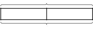
1503 The transmission of the checksum is illustrated in Figure 25. The LS byte is sent first, followed by the MS 1504 byte. Note that within the byte, the LS bit is sent first.
1505 |
|
1506 |
Figure 25 Checksum Transmission |
1507 An example of CRC implementation is presented in Figure 26. The CRC shift register shall be initialized to 1508 FFFFh before packet data enters. Packet payload data not including the header then enters as a bitwise data 1509 stream from the left. Each bit is fed through the CRC shift register before it is passed to output for 1510 transmission to the peripheral. After all pixels in the packet payload have passed the through the CRC shift 1511 register, the shift register contains the checksum. The checksum is then appended to the data stream and 1512 sent over DSI to the receiver. The receiver uses its own generated CRC to verify that no errors have 1513 occurred in transmission.
1514 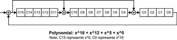 1515 Figure 26 Example implementation of CCITT 16-bit CRC generation using shift register
1516 Section 8.10.1 documents the peripheral response to detection of an error in Long packet payload.
Copyright © 2005-2006 MIPI Alliance, Inc. All rights reserved. MIPI Alliance Member Confidential.
69