

Version 1.00a 19-Apr-2006 MIPI Alliance Standard for DSI
1581 |
Annex A (Informative) |
|
|
|
||
1582 |
Contention Detection and Recovery |
|
||||
1583 |
Mechanisms |
|
|
|
||
1584 |
The following describes optional capabilities at the PHY and Protocol layers that provide additional |
|||||
1585 |
robustness for a DSI Link against possible data-signal contention as a consequence of transient errors in the |
|||||
1586 |
system. These capabilities improve the system’s chances of detecting any of several possible contention |
|||||
1587 |
cases, and provide mechanisms for “graceful” recovery without resorting to a hard reset. |
|
||||
1588 |
These capabilities combine circuitry in the I/O cell, to directly detect contention, with logic and timers in |
|||||
1589 |
the protocol to avert and recover from other forms of contention. |
|
||||
1590 |
A.1 PHY Detected Contention |
|
|
|
||
1591 |
The PHY can detect two types of contention faults: LP High Fault and LP Low Fault. |
|
||||
1592 |
An LP High Fault occurs when a LP transmitter is driving high and the pin voltage is less than VIL. |
|||||
1593 |
An LP Low Fault occurs when a LP transmitter is driving low and the pin voltage is greater than VILF. |
|||||
1594 |
The LP High Fault and LP Low Fault are caused by both sides of the Link transmitting simultaneously. |
|||||
1595 |
Note, the LP High Fault and LP Low Fault are only applicable for bidirectional Data Lanes. |
|||||
1596 |
A.1.1 Protocol Response to PHY Detected Faults |
|
||||
1597 |
The Protocol shall specify how both ends of the Link respond when contention is flagged. It shall ensure |
|||||
1598 |
that both devices return to Stop state (LP-11), with one side going to Stop TX and the other to Stop RX. |
|||||
1599 |
When both PHYs are in LP mode, one or both PHYs will detect contention between LP-0 and LP-1. |
|||||
1600 |
The following tables describe the resolution sequences for different types of contention and detection. |
|||||
1601 |
Table sequences: |
|
|
|
|
|
1602 |
• Sequence of events to resolve LP High ÅÆ LP Low Contention |
|
||||
1603 |
• Case 1: Both sides initially detect the contention |
|
||||
1604 |
• Case 2: Only the Host Processor initially detects contention |
|
||||
1605 |
• Case 3: Only the Peripheral initially detects contention |
|
||||
1606 |
|
Table 23 LP High ÅÆ LP Low Contention Case 1 |
|
|||
|
|
|
|
|
|
|
|
Host Processor Side |
Peripheral Side |
|
|||
|
|
|
|
|
|
|
|
Protocol |
|
PHY |
PHY |
|
Protocol |
|
|
|
|
|
|
|
|
|
|
Detect LP High Fault or |
Detect LP High Fault or |
|
|
|
|
|
LP Low Fault |
LP Low Fault |
|
|
|
|
|
|
|
|
|
Copyright © 2005-2006 MIPI Alliance, Inc. All rights reserved. MIPI Alliance Member Confidential.
73
Version 1.00a 19-Apr-2006 |
MIPI Alliance Standard for DSI |
||
|
|
|
|
Host Processor Side |
Peripheral Side |
||
|
|
|
|
Protocol |
PHY |
PHY |
Protocol |
|
|
|
|
|
Transition to Stop State |
Transition to LP-RX |
|
|
(LP-11) |
|
|
|
|
|
|
Host Processor Wait |
|
Peripheral waits until it |
|
Timeout |
|
observes Stop state |
|
|
|
before responding |
|
|
|
|
|
|
|
Observe Stop state |
|
|
|
|
|
Request Reset Entry |
Send Reset Entry |
Observe Reset Entry |
|
Command to PHY |
Command |
Command |
|
(optional) |
|
|
|
|
|
|
|
|
|
Flag Protocol about |
Observe Reset Entry |
|
|
Reset Command |
Command |
|
|
|
|
|
|
|
Reset Peripheral |
|
|
|
|
|
Return to Stop State |
Remain in LP-RX |
(reset may continue) |
|
(LP-11) |
|
|
|
|
|
|
Peripheral Reset |
Continue normal |
|
Reset completes |
Timeout. Wait until |
operation. |
|
|
Peripheral completes |
|
|
|
Reset before resuming |
|
|
|
normal operation. |
|
|
|
|
|
|
|
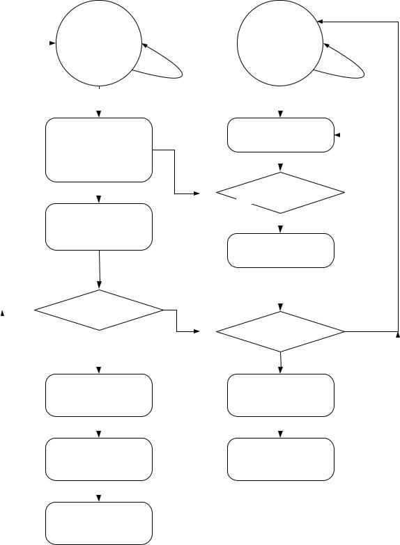
1607 Note: The protocol may want to request a Reset after contention is flagged a single time. Alternately, the 1608 protocol may choose not to Reset but instead continue normal operation after detecting a single contention. 1609 It could then initiate a Reset after multiple contentions are flagged, or never initiate a Reset.
Copyright © 2005-2006 MIPI Alliance, Inc. All rights reserved. MIPI Alliance Member Confidential.
74
Version 1.00a 19-Apr-2006 |
|
|
MIPI Alliance Standard for DSI |
||||||||||||
|
|
|
|
|
|
|
|
|
|
|
|
|
|
|
|
|
|
|
|
|
|
|
|
|
|
|
|
|
|
|
|
|
|
|
|
|
|
|
|
|
|
|
|
|
|
|
|
|
|
|
|
|
|
|
|
|
|
|
|
|
|
|
|
|
|
|
|
|
|
|
|
|
|
|
|
|
|
|
|
|
|
|
|
|
|
|
|
|
|
|
|
|
|
|
|
|
|
|
|
|
|
|
|
|
|
|
|
|
|
|
|
|
|
|
|
|
|
|
|
|
|
|
|
|
|
|
|
|
|
|
|
|
|
|
|
|
|
|
|
|
|
|
|
|
|
|
|
|
|
|
|
|
|
|
|
|
|
|
|
|
|
|
|
|
|
|
|
|
|
|
|
|
|
|
|
|
|
|
|
|
|
|
|
|
|
|
|
|
|
|
|
|
|
|
|
|
|
|
|
|
|
|
|
|
|
|
|
|
|
|
|
|
|
|
|
|
|
|
|
|
|
|
|
|
|
|
|
|
|
|
|
|
|
|
|
|
|
|
|
|
|
|
|
|
|
|
|
|
|
|
|
|
|
|
|
|
|
|
|
|
|
|
|
|
|
|
|
|
|
|
|
|
|
|
|
|
|
|
|
|
|
|
|
|
|
|
|
|
|
|
|
|
|
|
|
|
|
|
|
|
|
|
|
|
|
|
|
|
|
|
|
|
|
|
|
|
|
|
|
|
|
|
|
|
|
|
|
|
|
|
|
|
|
|
|
|
|
|
|
|
|
|
|
|
|
|
|
|
|
|
|
|
|
|
|
|
|
|
|
|
|
|
|
|
|
|
|
|
|
|
|
|
|
|
|
|
|
|
|
|
|
|
|
|
|
|
|
|
|
|
|
|
|
|
|
|
|
|
|
1610 |
|
1611 |
Figure 27 LP High ÅÆ LP Low Contention Case 1 |
Copyright © 2005-2006 MIPI Alliance, Inc. All rights reserved. MIPI Alliance Member Confidential.
75
|
Version 1.00a 19-Apr-2006 |
MIPI Alliance Standard for DSI |
||||
1612 |
|
Table 24 LP High ÅÆ LP Low Contention Case 2 |
|
|||
|
|
|
|
|
||
|
Host Processor Side |
Peripheral Side |
||||
|
|
|
|
|
|
|
|
Protocol |
|
PHY |
PHY |
|
Protocol |
|
|
|
|
|
|
|
|
|
|
Detect LP High Fault or |
No EL contention |
|
|
|
|
|
LP Low Fault |
detected |
|
|
|
|
|
|
|
|
|
|
|
|
Transition to Stop State |
No EL contention |
|
|
|
|
|
(LP-11) |
detected |
|
|
|
|
|
|
|
|
|
|
Host Processor Wait |
|
|
|
|
Peripheral Bus |
|
Timeout |
|
|
|
|
Possession Timeout |
|
|
|
|
|
|
|
|
|
|
|
Transition to LP-RX |
|
|
|
|
|
|
|
|
|
|
|
|
|
Observe Stop state |
|
|
|
|
|
|
|
|
|
|
Request Reset Entry |
|
Send Reset Entry |
Observe Reset Entry |
|
|
|
command to PHY |
|
command |
command |
|
|
|
|
|
|
|
|
|
|
|
|
|
Flag Protocol: Reset |
|
Observe Reset |
|
|
|
|
command received |
|
Command |
|
|
|
|
|
|
|
|
|
|
|
|
|
Reset Peripheral |
|
|
|
|
|
|
|
|
|
|
Return to Stop state (LP- |
Remain in LP-RX |
|
(reset continues) |
|
|
|
11) |
|
|
|
|
|
|
|
|
|
|
|
Peripheral Reset |
|
Continue normal |
|
|
Reset completes |
|
Timeout. Wait until |
|
operation. |
|
|
|
|
peripheral completes |
|
|
|
|
|
|
Reset before resuming |
|
|
|
|
|
|
normal operation. |
|
|
|
|
|
|
|
|
|
|
|
|
Copyright © 2005-2006 MIPI Alliance, Inc. All rights reserved. MIPI Alliance Member Confidential.
76
Version 1.00a 19-Apr-2006 |
|
MIPI Alliance Standard for DSI |
|||||||
|
|
|
Host Normal |
|
Peripheral |
||||
|
|
|
|
Normal |
|||||
|
|
|
Operation |
|
Operation |
||||
|
|
|
|
|
|
|
(Expanded) |
||
|
|
|
|
|
|
No Contention |
|
|
|
|
|
|
LP High/Low Fault |
Detected |
No Contention |
|
|||
|
|
|
Detected by LP-CD |
|
Detected |
|
|||
|
|
|
|
|
|
|
|
|
|
|
|
|
LP TX State |
STOP |
Peripheral Stops |
||
|
|
|
Transmitting |
||||
|
|
|
Drive ‘11’ to lines |
||||
|
|
|
Notify Protocol: |
|
|
||
|
|
|
|
|
|||
|
|
|
|
|
|||
|
|
|
ErrContention |
‘1’ |
|
|
|
|
|
|
|
|
|
Transition to LP RX |
|
|
|
|
|
|
|
||
|
|
|
|
|
|
|
|
|
|
|
Engine Wait Timeout |
|
|
||
|
|
|
|
|
|||
|
|
|
|
|
|||
|
|
|
|
|
|
LP RX observing ‘11’? |
|
|
|
|
|
|
|
|
YES |
|
|
|
|
|
|
LP RX State STOP |
|
|
NO |
|
Issue RESET? |
|
|
||
|
|
|
Observed |
||||
|
|
|
|
|
|
||
|
|
|
|
|
|
RESET? |
|
|
|
|
|
YES |
|
|
|
|
|
|
H/W RESET using |
|
YES |
||
|
|
|
LP Escape Mode |
|
|
||
|
|
|
|
|
|
Flag the Protocol: |
|
|
|
|
|
|
|
||
|
|
|
|
|
|
RESET |
|
|
|
|
LP TX State |
STOP |
|
|
|
|
|
|
|
|
|||
|
|
|
Drive ‘11’ to lines |
Stay in LP RX |
|||
|
|
|
|
|
|
||
|
|
|
|
|
|
Do not switch to LP TX |
|
|
|
|
Peripheral Reset |
||||
|
|
|
|
|
|||
1613 |
|
|
Timeout |
|
|
|
|
|
|
|
|
|
|
|
|
1614 |
|
|
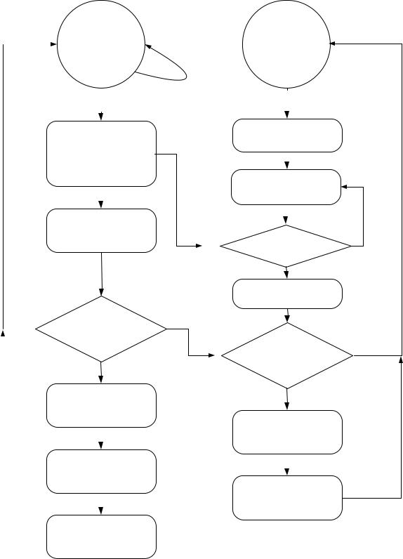
Figure 28 LP High ÅÆ LP Low Contention Case 2 |
||||
Copyright © 2005-2006 MIPI Alliance, Inc. All rights reserved. MIPI Alliance Member Confidential.
77
NO
NO
|
Version 1.00a 19-Apr-2006 |
|
|
|
MIPI Alliance Standard for DSI |
|||||
1615 |
|
Table 25 LP High ÅÆ LP Low Contention Case 3 |
|
|||||||
|
|
|
|
|
|
|
|
|
|
|
|
Host Processor Side |
|
|
|
Peripheral Side |
|
||||
|
|
|
|
|
|
|
|
|
|
|
|
Protocol |
|
PHY |
|
|
PHY |
|
|
Protocol |
|
|
|
|
|
|
|
|
|
|
|
|
|
|
|
No detection of |
EL |
Detect LP High Fault or |
|
|
|
||
|
|
|
contention |
|
LP Low Fault |
|
|
|
||
|
|
|
|
|
|
|
|
|
|
|
|
|
|
|
|
Transition to LP-RX |
|
|
|
||
|
|
|
|
|
|
|
|
|
|
|
|
|
|
|
|
Peripheral waits until it |
|
|
|
||
|
|
|
|
|
observes Stop state |
|
|
|
||
|
|
|
|
|
before responding to bus |
|
|
|
||
|
|
|
|
|
activity. |
|
|
|
||
|
|
|
|
|
|
|
|
|
|
|
|
|
|
Normal transition |
to |
Observe Stop State |
|
|
|
||
|
|
|
Stop State (LP-11) |
|
|
|
|
|
|
|
|
|
|
|
|
|
|
|
|
|
|
|
|
|
|
|
|
|
|
|
|
|
|
|
|
|
|
|
|
|
|
|
|
|
|
|
|
|
|
|
|
|
|
|
|
|
|
|
|
|
|
|
|
|
|
|
|
|
|
|
|
|
|
|
|
|
1616
1617
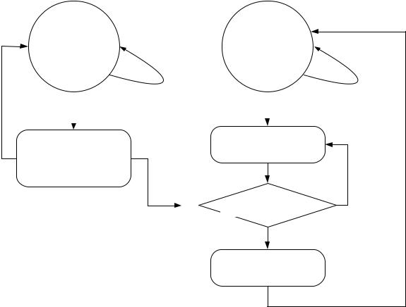
1618 Figure 29 LP High ÅÆ LP Low Contention Case 3
Copyright © 2005-2006 MIPI Alliance, Inc. All rights reserved. MIPI Alliance Member Confidential.
78