


Version 1.00a 19-Apr-2006 |
MIPI Alliance Standard for DSI |
3394 DSI Introduction
340DSI specifies the interface between a host processor and a peripheral such as a display module. It builds on
341existing MIPI Alliance standards by adopting pixel formats and command set specified in DPI-2, DBI-2
342and DCS standards.
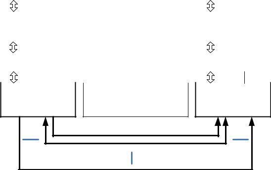
343Figure 1 shows a simplified DSI interface. From a conceptual viewpoint, a DSI-compliant interface
344performs the same functions as interfaces based on DBI-2 and DPI-2 standards or similar parallel display
345interfaces. It sends pixels or commands to the peripheral, and can read back status or pixel information
346from the peripheral. The main difference is that DSI serializes all pixel data, commands, and events that, in
347traditional or legacy interfaces, are normally conveyed to and from the peripheral on a parallel data bus
348with additional control signals.
349From a system or software point of view, the serialization and deserialization operations should be
350transparent. The most visible, and unavoidable, consequence of transformation to serial data and back to
351parallel is increased latency for transactions that require a response from the peripheral. For example,
352reading a pixel from the frame buffer on a display module will have a higher latency using DSI than DBI.
353Another fundamental difference is the host processor’s inability during a read transaction to throttle the
354rate, or size, of returned data.
355 |
|
356 |
Figure 1 DSI Transmitter and Receiver Interface |
Copyright © 2005-2006 MIPI Alliance, Inc. All rights reserved. MIPI Alliance Member Confidential.
15
|
Version 1.00a 19-Apr-2006 |
MIPI Alliance Standard for DSI |
357 |
4.1 DSI Layer Definitions |
|
Application Processor |
|
|
Peripheral |
||||||||||||||||||
|
|
|
|
|
|
|
|
|
|
|
|
|
|
|
|
|
|
|
|
|
|
|
|
|
|
|
|
|
|
|
|
|
Pixel to Byte Packing Formats |
|
|
|
|
|
|
|
|
|
|
|
|
Application |
|
Command Generation / Interpretation |
|
Application |
|||||||||||||||
|
Data |
|
Control |
|
|
Data |
|
Control |
|||||||||||||
|
|
|
|
|
|
||||||||||||||||
|
|
8 bits |
|
|
|
|
|
|
|
|
|
|
8 bits |
|
|
|
|
|
|
|
|
|
|
|
|
|
|
|
|
|
|
|
|
|
|
|
|
|
|
|
|
|
|
|
Data |
|
Control |
|
Packet Based Protocol |
|
Data |
|
Control |
||||||||||||
|
Low Level Protocol |
|
ECC and Checksum Generation and |
|
Low Level Protocol |
||||||||||||||||
|
Data |
|
Control |
|
Testing |
|
Data |
|
|
Control |
|||||||||||
|
|
|
|
|
|
|
|||||||||||||||
|
|
|
|
|
|
|
|
|
|
|
|
|
|
||||||||
|
|
8 bits |
|
|
|
|
|
|
|
|
|
|
8 bits |
|
|
|
|
|
|
|
|
|
|
|
|
|
|
|
|
|
|
|
|
|
|
|
|
|
|
|
|
|
|
|
Lane Management |
|
Lane Distribution and Merging |
|
Lane Management |
||||||||||||||||
|
|
|
|
||||||||||||||||||
|
|
|
|
|
|
|
|
|
|
|
|
|
|
|
|
|
|
|
|
||
|
(N+1) x 8 bits |
|
|
|
|
|
|
|
|
|
(N+1) x 8 bits |
|
|
|
|
|
|
||||
|
|
|
|
|
|
|
|
|
|
|
|
|
|
|
|
|
|
|
|
|
|
|
Data |
|
Control |
|
Start of Packet / End of Packet |
|
Data |
|
Control |
||||||||||||
|
|
|
|
|
|
|
|
|
|
|
|
|
|
|
|
|
|
|
|
|
|
|
|
PHY Layer |
Serializer / Deserializer |
|
|
PHY Layer |
|||||||||||||||
|
|
Clock Management (DDR) |
|
|
|||||||||||||||||
|
|
|
|
|
|
|
|
|
|
|
|
|
|
|
|
|
|
|
|
|
|
|
|
|
|
|
|
|
|
|
|
|
Electrical Layer (SLVS) |
|
|
|
|
|
|
|
|
|
|
High Speed Unidirectional Clock |
Lane 0 – High Speed Data (optionally Bidirectional in LP Mode) |
358 |
Lane N – High Speed Unidirectional Data |
|
|
359 |
Figure 2 DSI Layers |
360A conceptual view of DSI organizes the interface into several functional layers. A description of the layers
361follows and is also shown in Figure 2.
362PHY Layer: The PHY Layer specifies transmission medium (electrical conductors), the input/output
363circuitry and the clocking mechanism that captures “ones” and “zeroes” from the serial bit stream. This part
364of the specification documents the characteristics of the transmission medium, electrical parameters for
365signaling and the timing relationship between clock and Data Lanes.
366The mechanism for signaling Start of Transmission (SoT) and End of Transmission (EoT) is specified, as
367well as other “out of band” information that can be conveyed between transmitting and receiving PHYs.
368Bit-level and byte-level synchronization mechanisms are included as part of the PHY. Note that the
369electrical basis for DSI (SLVS) has two distinct modes of operation, each with its own set of electrical
370parameters.
371The PHY layer is described in MIPI Alliance Standard for D-PHY [4].
372Lane Management Layer: DSI is Lane-scalable for increased performance. The number of data signals
373may be 1, 2, 3, or 4 depending on the bandwidth requirements of the application. The transmitter side of the
374interface distributes the outgoing data stream to one or more Lanes (“distributor” function). On the
375receiving end, the interface collects bytes from the Lanes and merges them together into a recombined data
376stream that restores the original stream sequence (“merger” function).
Copyright © 2005-2006 MIPI Alliance, Inc. All rights reserved. MIPI Alliance Member Confidential.
16