

|
Version 1.00a 19-Apr-2006 |
MIPI Alliance Standard for DSI |
1251 |
Checksum appended to the N-byte payload data. If the peripheral does not support Checksum it shall return |
|
1252 |
0000h. |
|
1253 |
If the command itself is possibly corrupt, due to an uncorrectable ECC error, SoT or SoT Sync error, the |
|
1254 |
requested READ data packet shall not be sent after the Acknowledge with Error Report packet. |
|
1255 |
8.10.4 DCS Long Read Response with Optional ECC and Checksum, Data Type 01 1100 |
|
1256 |
(1Ch) |
|
1257 |
This is a Long packet response to DCS Read Request. Packet composition is the Data Identifier (DI) byte |
|
1258 |
followed by a two-byte Word Count, an ECC byte, N bytes of payload, and a two-byte Checksum. If the |
|
1259 |
peripheral is ECC-capable, it shall check the incoming command for errors and return the requested READ |
|
1260 |
data with ECC byte appended to the header (DI + Word Count). If the peripheral does not support ECC it |
|
1261 |
shall return 00h. If the peripheral is Checksum capable, it shall return a calculated two-byte Checksum |
|
1262 |
appended to the N-byte payload data. If the peripheral does not support Checksum it shall return 0000h. |
|
1263 |
If the DCS command itself is possibly corrupt, due to uncorrectable ECC error, SoT or SoT Sync error, the |
|
1264 |
requested READ data packet shall not be sent after the Acknowledge with Error Report packet. |
|
1265 |
8.10.5 DCS Short Read Response with Optional ECC, Data Type 10 0xxx (20h – 27h) |
|
1266 |
This is the short-packet response to DCS Read Request. Packet composition is the Data Identifier (DI) byte |
|
1267 |
followed by up to seven bytes of payload data followed by an ECC byte. Data Type (DT) bits [2:0] indicate |
|
1268 |
the number of payload bytes in the packet. If the peripheral is ECC-capable, it shall check the incoming |
|
1269 |
request for errors, and return the requested READ data with ECC byte appended to the packet covering up |
|
1270 |
to eight bytes (DI + payload data). |
|
1271 |
8.10.6 Multiple-packet Transmission and Error Reporting |
|
1272 |
A peripheral shall flag and report all errors that are detected in a transmission, if bus possession is given to |
|
1273 |
the peripheral at the end of the transmission. Only one ACK + Error Report shall be returned per |
|
1274 |
transmission, regardless of the number of packets in the transmission. If a transmission contained multiple |
|
1275 |
packets it may not be possible to associate a particular error with the packet that generated it. |
|
1276 |
If collecting error reports from each and every packet is a high priority, software can send command and |
|
1277 |
data packets individually, one per transmission. In addition, a peripheral may choose to store accumulated |
|
1278 |
results in memory on the peripheral, and the host processor may recover the record with a block read from |
|
1279 |
memory at a later time. |
|
1280 |
8.10.7 Clearing Error Bits |
|
1281 |
Once reported, DSI error flags shall be cleared by the peripheral. If bus possession is not given to the |
|
1282 |
peripheral before the next processor-to-peripheral transmission, any error information from the first |
|
1283 |
transmission shall be cleared from the DSI error register before reporting the error information for the next |
|
1284 |
processor-to-peripheral transmission. Note that this does not preclude retaining the error information |
|
1285 |
internally on the peripheral. However it is not stored and transmitted as part of a subsequent ACK + Error |
|
1286 |
Report response. |
|
1287 |
8.11 Video Mode Interface Timing |
|
1288 |
Video Mode peripherals require pixel data delivered in real time. This section specifies the format and |
|
1289 |
timing of DSI traffic for this type of display module. |
|
Copyright © 2005-2006 MIPI Alliance, Inc. All rights reserved. MIPI Alliance Member Confidential.
56
|
Version 1.00a 19-Apr-2006 |
MIPI Alliance Standard for DSI |
|||||||||||||||||||||||
1290 |
8.11.1 Traffic Sequences |
|
|||||||||||||||||||||||
1291 |
The host processor shall support all of the traffic sequences in this section. A Video Mode peripheral shall |
||||||||||||||||||||||||
1292 |
support at least one of the traffic sequences in this section. The peripheral shall not require any additional |
||||||||||||||||||||||||
1293 |
constraints regarding traffic sequence or packet timing. The peripheral supplier shall document all relevant |
||||||||||||||||||||||||
1294 |
timing parameters listed in Table 19. |
|
|||||||||||||||||||||||
1295 |
In the following figures BLLP is defined as a period during which video packets such as pixel-stream and |
||||||||||||||||||||||||
1296 |
sync event packets are not actively transmitted to the peripheral. |
|
|||||||||||||||||||||||
1297 |
To enable PHY synchronization the host processor should periodically end HS transmission and drive the |
||||||||||||||||||||||||
1298 |
Data Lanes to the LP state. This transition should take place at least once per frame; shown as LPM in the |
||||||||||||||||||||||||
1299 |
figures in this section. It is recommended to return to LP state once per scanline during the horizontal |
||||||||||||||||||||||||
1300 |
blanking time. Regardless of the frequency of BLLP periods, the host processor is responsible for meeting |
||||||||||||||||||||||||
1301 |
all documented peripheral timing requirements. Note, at lower frequencies BLLP periods will approach, or |
||||||||||||||||||||||||
1302 |
become, zero, and burst mode will be indistinguishable from non-burst mode. |
||||||||||||||||||||||||
1303 |
During the BLLP the DSI Link may do any of the following: |
|
|||||||||||||||||||||||
1304 |
• Remain in Idle Mode with the host processor in LP-11 state and the peripheral in LP-RX |
||||||||||||||||||||||||
1305 |
• Transmit one or more non-video packets from the host processor to the peripheral using Escape |
||||||||||||||||||||||||
1306 |
Mode |
|
|||||||||||||||||||||||
1307 |
• Transmit one or more non-video packets from the host processor to the peripheral using HS Mode |
||||||||||||||||||||||||
1308 |
• If the previous processor-to-peripheral transmission ended with BTA, transmit one or more |
||||||||||||||||||||||||
1309 |
packets from the peripheral to the host processor using Escape Mode |
||||||||||||||||||||||||
1310 |
• Transmit one or more packets in HS Mode from the host processor to a different peripheral using a |
||||||||||||||||||||||||
1311 |
different Virtual Channel ID |
|
|||||||||||||||||||||||
1312 |
In HS transmissions containing multiple packets, such as BLLP and RGB, the sequence of packets is |
||||||||||||||||||||||||
1313 |
arbitrary. The host processor may compose any sequence of packets, including iterations, within the limits |
||||||||||||||||||||||||
1314 |
of the packet format definitions. For all timing cases, the first line of a frame shall start with VS; all other |
||||||||||||||||||||||||
1315 |
lines shall start with HS. This is also true in the special case when VSA+VBP=0. Note that the position of |
||||||||||||||||||||||||
1316 |
synchronization packets, such as VS and HS, in time is of utmost importance since this has a direct impact |
||||||||||||||||||||||||
1317 |
on the visual performance of the display panel. |
|
|||||||||||||||||||||||
1318 |
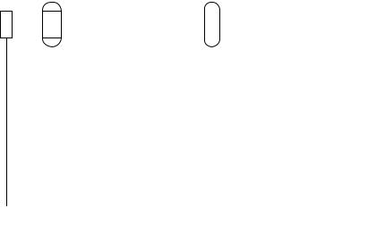
Traffic units used in the figures in this section are defined in Figure 19 unless otherwise specified. |
||||||||||||||||||||||||
|
|
|
|
|
|
|
|
|
|
|
|
|
|
|
|
|
|
|
|
|
|
|
|
|
|
|
|
|
|
|
|
|
|
|
|
|
|
|
|
|
|
|
|
|
|
|
|
|
|
|
|
|
|
|
|
|
|
|
|
|
|
|
|
|
|
|
|
|
|
|
|
|
|
|
|
|
|
|
|
|
|
|
|
|
|
|
|
|
|
|
|
|
|
|
|
|
|
|
|
|
|
|
|
|
|
|
|
|
|
|
|
|
|
|
|
|
|
|
|
|
|
|
|
|
|
|
|
|
|
|
|
|
|
|
|
|
|
|
|
|
|
|
|
|
|
|
|
|
|
|
|
|
|
|
|
|
|
|
|
|
|
|
|
|
|
|
|
|
|
|
|
|
|
|
|
|
|
|
|
|
|
|
|
|
|
|
|
|
|
|
|
|
|
|
|
|
|
|
|
|
|
|
|
|
|
|
|
|
|
|
|
|
|
|
|
|
|
|
|
|
|
|
|
|
|
|
|
|
|
|
|
|
|
|
|
|
|
|
|
|
|
|
|
|
|
|
|
|
|
|
|
|
|
|
|
|
|
|
|
|
|
|
|
|
|
|
|
|
|
|
|
|
|
|
|
|
|
|
|
|
|
|
|
|
|
|
|
|
|
|
|
|
|
|
|
|
|
|
|
|
|
|
|
|
|
|
|
|
|
|
|
1319 |
|
1320 |
Figure 19 DSI Video Mode Interface Timing Legend |
Copyright © 2005-2006 MIPI Alliance, Inc. All rights reserved. MIPI Alliance Member Confidential.
57
Version 1.00a 19-Apr-2006 |
MIPI Alliance Standard for DSI |
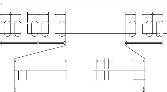
1321 8.11.2 Non-Burst Mode with Sync Pulses
1322 With this format, the goal is to accurately convey DPI-type timing over the DSI serial Link. This includes 1323 matching DPI pixel-transmission rates, and widths of timing events like sync pulses. Accordingly, 1324 synchronization periods are defined using packets transmitting both start and end of sync pulses. An 1325 example of this mode is shown in Figure 20.
1326
1327
1328 |
Figure 20 DSI Video Mode Interface Timing: Non-burst Communication with Start and End |
1329 |
8.11.3 Non-Burst Mode with Sync Events |
1330 |
This mode is a simplification of the format described in section 8.11.2. Only the start of each |
1331 |
synchronization pulse is transmitted. The peripheral may regenerate sync pulses as needed from each Sync |
1332 |
Event packet received. Pixels are transmitted at the same rate as they would in a corresponding parallel |
1333 |
display interface such as DPI-2. An example of this mode is shown in Figure 21. |
Copyright © 2005-2006 MIPI Alliance, Inc. All rights reserved. MIPI Alliance Member Confidential.
58

Version 1.00a 19-Apr-2006 |
|
|
|
|
|
|
|
|
|
|
|
|
|
MIPI Alliance Standard for DSI |
|||||||||||||||||||||||||||||||||||||||||||||||||
|
|
|
|
|
|
|
|
|
|
|
|
|
|
|
|
|
|
|
|
|
|
|
|
|
|
|
|
|
|
|
|
|
|
|
|
|
|
|
|
|
|
|
|
|
|
|
|
|
|
|
|
|
|
|
|
|
|
|
|
|
|
|
|
|
|
|
|
|
|
|
|
|
|
|
|
|
|
|
|
|
|
|
|
|
|
|
|
|
|
|
|
|
|
|
|
|
|
|
|
|
|
|
|
|
|
|
|
|
|
|
|
|
|
|
|
|
|
|
|
|
|
|
|
|
|
|
|
|
|
|
|
|
|
|
|
|
|
|
|
|
|
|
|
|
|
|
|
|
|
|
|
|
|
|
|
|
|
|
|
|
|
|
|
|
|
|
|
|
|
|
|
|
|
|
|
|
|
|
|
|
|
|
|
|
|
|
|
|
|
|
|
|
|
|
|
|
|
|
|
|
|
|
|
|
|
|
|
|
|
|
|
|
|
|
|
|
|
|
|
|
|
|
|
|
|
|
|
|
|
|
|
|
|
|
|
|
|
|
|
|
|
|
|
|
|
|
|
|
|
|
|
|
|
|
|
|
|
|
|
|
|
|
|
|
|
|
|
|
|
|
|
|
|
|
|
|
|
|
|
|
|
|
|
|
|
|
|
|
|
|
|
|
|
|
|
|
|
|
|
|
|
|
|
|
|
|
|
|
|
|
|
|
|
|
|
|
|
|
|
|
|
|
|
|
|
|
|
|
|
|
|
|
|
|
|
|
|
|
|
|
|
|
|
|
|
|
|
|
|
|
|
|
|
|
|
|
|
|
|
|
|
|
|
|
|
|
|
|
|
|
|
|
|
|
|
|
|
|
|
|
|
|
|
|
|
|
|
|
|
|
|
|
|
|
|
|
|
|
|
|
|
|
|
|
|
|
|
|
|
|
|
|
|
|
|
|
|
|
|
|
|
|
|
|
|
|
|
|
|
|
|
|
|
|
|
|
|
|
|
|
|
|
|
|
|
|
|
|
|
|
|
|
|
|
|
|
|
|
|
|
|
|
|
|
|
|
|
|
|
|
|
|
|
|
|
|
|
|
|
|
|
|
|
|
|
|
|
|
|
|
|
|
|
|
|
|
|
|
|
|
|
|
|
|
|
|
|
|
|
|
|
|
|
|
|
|
|
|
|
|
|
|
|
|
|
|
|
|
|
|
|
|
|
|
|
|
|
|
|
|
|
|
|
|
|
|
|
|
|
|
|
|
|
|
|
|
|
|
|
|
|
|
|
|
|
|
|
|
|
|
|
|
|
|
|
|
|
|
|
|
|
|
|
|
|
|
|
|
|
|
|
|
|
|
|
|
|
|
|
|
|
|
|
|
|
|
|
|
|
|
|
|
|
|
|
|
|
|
|
|
|
|
|
|
|
|
|
|
|
|
|
|
|
|
|
|
|
|
|
|
|
|
|
|
|
|
|
|
|
|
|
|
|
|
|
|
|
|
|
|
|
|
|
|
|
|
|
|
|
|
|
|
|
|
|
|
|
|
|
|
|
|
|
|
|
|
|
|
|
|
|
|
|
|
|
|
|
|
|
|
|
|
|
|
|
|
|
|
|
|
|
|
|
|
|
|
|
|
|
|
|
|
|
|
|
|
|
|
|
|
|
|
|
|
|
|
|
|
|
|
|
|
|
|
|
|
|
|
|
|
|
|
|
|
|
|
|
|
|
|
|
|
|
|
|
|
|
|
|
|
|
|
|
|
|
|
|
|
|
|
|
|
|
|
|
|
|
|
|
|
|
|
|
|
|
|
|
|
|
|
|
|
|
|
|
|
|
|
|
|
|
|
|
|
|
|
|
|
|
|
|
|
|
|
|
|
|
|
|
|
|
|
|
|
|
|
|
|
|
|
|
|
|
|
|
|
|
|
|
|
|
|
|
|
|
|
|
|
|
|
|
|
|
|
|
|
|
|
|
|
|
|
|
|
|
|
|
|
|
|
|
|
|
|
|
|
|
|
|
|
|
|
|
|
|
|
|
|
|
|
|
|
|
|
|
|
|
|
|
|
|
|
|
|
|
|
|
|
|
|
|
|
|
|
|
|
|
|
|
|
|
|
|
|
|
|
|
|
|
|
|
|
|
|
|
|
|
|
|
|
|
|
|
|
|
|
|
|
|
|
|
|
|
|
|
|
|
|
|
|
|
|
|
|
|
|
|
|
|
|
|
|
|
|
|
|
|
|
|
|
|
|
|
|
|
|
|
|
|
|
|
|
|
|
|
|
|
|
|
|
|
|
|
|
|
|
|
|
|
|
|
|
|
|
|
|
|
|
|
|
|
|
|
|
|
|
|
|
|
|
|
|
|
|
|
|
|
|
|
|
|
|
|
|
|
|
|
|
|
|
|
|
|
|
|
|
|
|
|
|
|
|
|
|
|
|
|
|
|
|
|
|
|
|
|
|
|
1334
1335
1336 Figure 21 DSI Video Mode Interface Timing: Non-burst Communication
1337 8.11.4 Burst Mode
1338 In this mode, blocks of pixel data can be transferred in a short time using a compressed burst format. This 1339 is a good strategy to reduce overall DSI power consumption, as well as enabling larger blocks of time for 1340 other data transmissions over the Link in either direction.
1341 There may be a line buffer or similar memory on the peripheral to accommodate incoming data at high 1342 speed. Following HS pixel data transmission, the bus goes to Low Power Mode, during which it may 1343 remain idle, i.e. the host processor remains in LP-11 state, or LP transmission may take place in either 1344 direction. If the peripheral takes control of the bus for sending data to the host processor, its transmission 1345 time shall be limited to ensure data underflow does not occur from its internal buffer memory to the display 1346 device. An example of this mode is shown in Figure 22.
Copyright © 2005-2006 MIPI Alliance, Inc. All rights reserved. MIPI Alliance Member Confidential.
59