- •1 Overview
- •1.1 Scope
- •1.2 Purpose
- •2 Terminology (Informational)
- •2.1 Definitions
- •2.2 Abbreviations
- •2.3 Acronyms
- •3 References (Informational)
- •3.1 DBI and DBI-2 (Display Bus Interface Standards for Parallel Signaling)
- •3.2 DPI and DPI-2 (Display Pixel Interface Standards for Parallel Signaling)
- •3.3 DCS (Display Command Set)
- •3.4 CSI-2 (Camera Serial Interface 2)
- •3.5 D-PHY (MIPI Alliance Standard for Physical Layer)
- •4 DSI Introduction
- •4.1 DSI Layer Definitions
- •4.2 Command and Video Modes
- •4.2.1 Command Mode
- •4.2.2 Video Mode Operation
- •4.2.3 Virtual Channel Capability
- •5 DSI Physical Layer
- •5.1 Data Flow Control
- •5.2 Bidirectionality and Low Power Signaling Policy
- •5.3 Command Mode Interfaces
- •5.4 Video Mode Interfaces
- •5.5 Bidirectional Control Mechanism
- •5.6 Clock Management
- •5.6.1 Clock Requirements
- •5.6.2 Clock Power and Timing
- •6 Multi-Lane Distribution and Merging
- •6.1 Multi-Lane Interoperability and Lane-number Mismatch
- •6.1.1 Clock Considerations with Multi-Lane
- •6.1.2 Bi-directionality and Multi-Lane Capability
- •6.1.3 SoT and EoT in Multi-Lane Configurations
- •7 Low-Level Protocol Errors and Contention
- •7.1 Low-Level Protocol Errors
- •7.1.1 SoT Error
- •7.1.2 SoT Sync Error
- •7.1.3 EoT Sync Error
- •7.1.4 Escape Mode Entry Command Error
- •7.1.5 LP Transmission Sync Error
- •7.1.6 False Control Error
- •7.2 Contention Detection and Recovery
- •7.2.1 Contention Detection in LP Mode
- •7.2.2 Contention Recovery Using Timers
- •7.3 Additional Timers
- •7.3.1 Turnaround Acknowledge Timeout (TA_TO)
- •7.3.2 Peripheral Reset Timeout (PR_TO)
- •7.4 Acknowledge and Error Reporting Mechanism
- •8 DSI Protocol
- •8.1 Multiple Packets per Transmission
- •8.2 Packet Composition
- •8.3 Endian Policy
- •8.4 General Packet Structure
- •8.4.1 Long Packet Format
- •8.4.2 Short Packet Format
- •8.5 Common Packet Elements
- •8.5.1 Data Identifier Byte
- •8.5.2 Error Correction Code
- •8.6 Interleaved Data Streams
- •8.6.1 Interleaved Data Streams and Bi-directionality
- •8.7 Processor to Peripheral Direction (Processor-Sourced) Packet Data Types
- •8.8 Processor-to-Peripheral Transactions – Detailed Format Description
- •8.8.1 Sync Event (H Start, H End, V Start, V End), Data Type = xx 0001 (x1h)
- •8.8.2 Color Mode On Command, Data Type = 00 0010 (02h)
- •8.8.3 Color Mode Off Command, Data Type = 01 0010 (12h)
- •8.8.4 Shutdown Peripheral Command, Data Type = 10 0010 (22h)
- •8.8.5 Turn On Peripheral Command, Data Type = 11 0010 (32h)
- •8.8.6 Generic Short WRITE Packet, 0 to 7 Parameters, Data Type = xx x011 (x3h and xBh)
- •8.8.7 Generic READ Request, 0 to 7 Parameters, Data Type = xx x100 (x4h and xCh)
- •8.8.8 DCS Commands
- •8.8.9 Set Maximum Return Packet Size, Data Type = 11 0111 (37h)
- •8.8.10 Null Packet (Long), Data Type = 00 1001 (09h)
- •8.8.11 Blanking Packet (Long), Data Type = 01 1001 (19h)
- •8.8.12 Generic Non-Image Data (Long), Data Type = 10 1001 (29h)
- •8.8.13 Packed Pixel Stream, 16-bit Format, Long packet, Data Type 00 1110 (0Eh)
- •8.8.14 Packed Pixel Stream, 18-bit Format, Long packet, Data type = 01 1110 (1Eh)
- •8.8.15 Pixel Stream, 18-bit Format in Three Bytes, Long packet, Data Type = 10 1110 (2Eh)
- •8.8.16 Packed Pixel Stream, 24-bit Format, Long packet, Data Type = 11 1110 (3Eh)
- •8.8.17 DO NOT USE and Reserved Data Types
- •8.9 Peripheral-to-Processor (Reverse Direction) LP Transmissions
- •8.9.1 Packet Structure for Peripheral-to-Processor LP Transmissions
- •8.9.2 System Requirements for ECC and Checksum and Packet Format
- •8.9.3 Appropriate Responses to Commands and ACK Requests
- •8.9.4 Format of Acknowledge with Error Report and Read Response Data Types
- •8.9.5 Error-Reporting Format
- •8.10 Peripheral-to-Processor Transactions – Detailed Format Description
- •8.10.1 Acknowledge with Error Report, Data Type 00 0010 (02h)
- •8.10.2 Generic Short Read Response with Optional ECC, Data Type 01 0xxx (10h – 17h)
- •8.10.5 DCS Short Read Response with Optional ECC, Data Type 10 0xxx (20h – 27h)
- •8.10.6 Multiple-packet Transmission and Error Reporting
- •8.10.7 Clearing Error Bits
- •8.11 Video Mode Interface Timing
- •8.11.1 Traffic Sequences
- •8.11.2 Non-Burst Mode with Sync Pulses
- •8.11.3 Non-Burst Mode with Sync Events
- •8.11.4 Burst Mode
- •8.11.5 Parameters
- •8.12 TE Signaling in DSI
- •9 Error-Correcting Code (ECC) and Checksum
- •9.1 Hamming Code for Packet Header Error Detection/Correction
- •9.2 Hamming-modified Code for DSI
- •9.3 ECC Generation on the Transmitter and Byte-Padding
- •9.4 Applying ECC and Byte-Padding on the Receiver
- •9.5 Checksum Generation for Long Packet Payloads
- •10 Compliance, Interoperability, and Optional Capabilities
- •10.1 Display Resolutions
- •10.2 Pixel Formats
- •10.3 Number of Lanes
- •10.4 Maximum Lane Frequency
- •10.5 Bidirectional Communication
- •10.6 ECC and Checksum Capabilities
- •10.7 Display Architecture
- •10.8 Multiple Peripheral Support
- •A.1 PHY Detected Contention
- •A.1.1 Protocol Response to PHY Detected Faults
Version 1.00a 19-Apr-2006 |
MIPI Alliance Standard for DSI |
799Packet sizes fall into two categories:
800• Short packets specify the payload length using the Data Type field and are from two to nine bytes
801in length. See Table 16 and Table 18 for payload lengths. Short packets are used for most
802Command Mode commands and associated parameters. Other Short packets convey events like H
803Sync and V Sync edges. Because they are Short packets they can convey accurate timing
804information to logic at the peripheral.
805• Long packets specify the payload length using a two-byte Word Count field. Payloads may be
806from 0 to 216 - 1 bytes long. Therefore, a Long packet may be up to 65,541 bytes in length. Long
807packets permit transmission of large blocks of pixel or other data.
808A special case of Command Mode operation is video-rate (update) streaming, which takes the form of an
809arbitrarily long stream of pixel or other data transmitted to the peripheral. As all DSI transactions use
810packets, the video stream shall be broken into separate packets. This “packetization” may be done by
811hardware or software. The peripheral may then reassemble the packets into a continuous video stream for
812display.
813The Set Maximum Return Packet Size command allows the host processor to limit the size of response
814packets coming from a peripheral. See section 8.8.8.3 for a description of the command.
8158.3 Endian Policy
816All packet data traverses the interface as bytes. Sequentially, a transmitter shall send data LSB first, MSB
817last. For packets with multibyte fields, the least significant byte shall be transmitted first except as indicated
818in the packet definition.
8198.4 General Packet Structure
820Two packet structures are defined for low-level protocol communication: Long packets and Short packets.
821For both packet structures, the Data Identifier is always the first byte of the packet.
8228.4.1 Long Packet Format
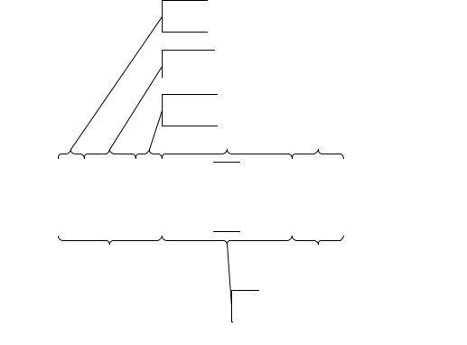
823Figure 10 shows the structure of the Long packet. A Long packet shall consist of three elements: a 32-bit
824Packet Header (PH), an application-specific Data Payload with a variable number of bytes, and a 16-bit
825Packet Footer (PF). The Packet Header is further composed of three elements: an 8-bit Data Identifier, a
82616-bit Word Count, and 8-bit ECC. The Packet Footer has one element, a 16-bit checksum. Long packets
827can be from 6 to 65,541 bytes in length.
Copyright © 2005-2006 MIPI Alliance, Inc. All rights reserved. MIPI Alliance Member Confidential.
38
Version 1.00a 19-Apr-2006 |
|
|
|
|
|
|
MIPI Alliance Standard for DSI |
|||||||
|
|
|
|
|
|
|
|
|
|
|
|
|
|
|
|
|
|
|
|
|
|
|
|
|
|
|
|
|
|
828 |
|
829 |
Figure 10 Long Packet Structure |
830The Data Identifier defines the Virtual Channel for the data and the Data Type for the application specific
831payload data. See sections 8.8 through 8.10 for descriptions of Data Types.
832The Word Count defines the number of bytes in the Data Payload between the end of the Packet Header
833and the start of the Packet Footer. Neither the Packet Header nor the Packet Footer shall be included in the
834Word Count.
835The Error Correction Code (ECC) byte allows single-bit errors to be corrected and 2-bit errors to be
836detected in the Packet Header. This includes both the Data Identifier and Word Count fields.
837After the end of the Packet Header, the receiver reads the next Word Count * bytes of the Data Payload.
838Within the Data Payload block, there are no limitations on the value of a data word, i.e. no embedded codes
839are used.
840Once the receiver has read the Data Payload it reads the Checksum in the Packet Footer. The host processor
841shall always calculate and transmit a Checksum in the Packet Footer. Peripherals are not required to
842calculate a Checksum. Also note the special case of zero-byte Data Payload: if the payload has length 0,
843then the Checksum calculation results in (FFFFh). If the Checksum is not calculated, the Packet Footer
844shall consist of two bytes of all zeros (0000h). See section 9 for more information on calculating the
845Checksum.
846In the generic case, the length of the Data Payload shall be a multiple of bytes. In addition, each data format
847may impose additional restrictions on the length of the payload data, e.g. multiple of four bytes.
848Each byte shall be transmitted least significant bit first. Payload data may be transmitted in any byte order
849restricted only by data format requirements. Multi-byte elements such as Word Count and Checksum shall
850be transmitted least significant byte first.
Copyright © 2005-2006 MIPI Alliance, Inc. All rights reserved. MIPI Alliance Member Confidential.
39