

Version 1.00a 19-Apr-2006 |
MIPI Alliance Standard for DSI |
4315 DSI Physical Layer
432This section provides a brief overview of the physical layer used in DSI. See MIPI Alliance Standard for
433D-PHY [4] for more details.
434Information is transferred between host processor and peripheral using one or more serial data signals and
435accompanying serial clock. The action of sending high-speed serial data across the bus is called a HS
436transmission or burst.
437Between transmissions, the differential data signal or Lane goes to a low-power state (LPS). Interfaces
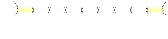
438should be in LPS when they are not actively transmitting or receiving high-speed data. Figure 3 shows the
439basic structure of a HS transmission. N is the total number of bytes sent in the transmission.
440 |
|
441 |
Figure 3 Basic HS Transmission Structure |
442D-PHY low-level protocol specifies a minimum data unit of one byte, and a transmission contains an
443integer number of bytes.
4445.1 Data Flow Control
445There is no handshake between the Protocol and PHY layers that permit the Protocol layer to throttle data
446transfer to, or from, the PHY layer once transmission is underway. Packets shall be sent and received in
447their entirety and without interruption. The Protocol layer and data buffering on both ends of the Link shall
448always have bandwidth equal to, or greater than, PHY layer circuitry. A practical consequence is that the
449system implementer should ensure that receivers have bandwidth capability that is equal to, or greater than,
450that of the transmitter.
4515.2 Bidirectionality and Low Power Signaling Policy
452The physical layer for a DSI implementation is composed of one to four Data Lanes and one Clock Lane.
453 In a Command Mode system, Data Lane 0 shall be bidirectional; additional Data Lanes shall be
454unidirectional. In a Video Mode system, Data Lane 0 may be bidirectional or unidirectional; additional
455Data Lanes shall be unidirectional. See sections 5.3 and 5.4 for details.
456For both interface types, the Clock Lane shall be driven by the host processor only, never by the peripheral.
457Forward direction Low Power transmissions shall use Data Lane 0 only. Reverse direction transmissions on
458Data Lane 0 shall use Low Power Mode only. The peripheral shall be capable of receiving any transmission
459in Low Power or High Speed Mode. Note that transmission bandwidth is substantially reduced when
460transmitting in LP mode.
461For bidirectional Lanes, data shall be transmitted in the peripheral-to-processor, or reverse, direction using
462Low-Power (LP) Mode only. See MIPI Alliance Standard for D-PHY [4] for details on the different modes
463of transmission.
Copyright © 2005-2006 MIPI Alliance, Inc. All rights reserved. MIPI Alliance Member Confidential.
19
Version 1.00a 19-Apr-2006 |
MIPI Alliance Standard for DSI |
464The interface between PHY and Protocol layers has several signals controlling bus direction. When a host
465transmitter requires a response from a peripheral, e.g. returning READ data or status information, it asserts
466TurnRequest to its PHY during the last packet of the transmission. This tells the PHY layer to assert the
467Bus Turn-Around (BTA) command following the EoT sequence.
468When a peripheral receives the Bus Turn-Around command, its PHY layer asserts TurnRequest as an input
469to the Protocol layer. This tells the receiving Protocol layer that it shall prepare to send a response to the
470host processor. Normally, the packet just received will tell the Protocol layer what information to send once
471the bus is available for transmitting to the host processor.
472After transmitting its response, the peripheral similarly hands bus control back to the host processor using a
473TurnRequest to its own PHY layer.
4745.3 Command Mode Interfaces
475The minimum physical layer requirement for a DSI host processor operating in Command Mode is:
476• Data Lane Module: CIL-MUYY (HS-TX, LP-TX, LP-RX, and LP-CD)
477• Clock Lane Module: CIL-MCNN (HS-TX, LP-TX)
478The minimum physical layer requirement for a DSI peripheral operating in Command Mode is:
479• Data Lane Module: CIL-SUYY (HS-RX, LP-RX, LP-TX, and LP-CD)
480• Clock Lane Module: CIL-SCNN (HS-RX, LP-RX)
481Bidirectional Links shall support reverse-direction Escape Mode as well as forward direction Escape Mode.
4825.4 Video Mode Interfaces
483The minimum physical layer requirement for a DSI transmitter operating in Video Mode is:
484• Data Lane Module: CIL-MUNN (HS-TX, LP-TX)
485• Clock Lane Module: CIL-MCNN (HS-TX, LP-TX)
486The minimum physical layer requirement for a DSI receiver operating in Video Mode is:
487• Data Lane Module: CIL-SUNN (HS-RX, LP-RX)
488• Clock Lane Module: CIL-SCNN (HS-RX, LP-RX)
489All DSI implementations should support forward escape ULPM on all Data Lanes.
4905.5 Bidirectional Control Mechanism
491Turning the bus around is controlled by a token-passing mechanism: the host processor sends a Bus Turn-
492Around (BTA) request, which conveys to the peripheral its intention to release, or stop driving, the data
493path after which the peripheral can transmit one or more packets back to the host processor. When it is
494finished, the peripheral shall return control of the bus back to the host processor. Bus Turn-Around is
495signaled using an Escape Mode mechanism provided by PHY-level protocol.
Copyright © 2005-2006 MIPI Alliance, Inc. All rights reserved. MIPI Alliance Member Confidential.
20