

Interfacing with C plus plus-programing communication with microcontrolers (K. Bentley, 2006)
.pdf52 3 TESTING THE PARALLEL PORT
// Examples: |
7 |
6 |
5 |
4 |
3 |
2 |
1 |
0 |
|
// |
Bit No: |
||||||||
// |
0x0F |
0 |
0 |
0 |
0 |
1 |
1 |
1 |
1 |
// |
0x05 |
0 |
0 |
0 |
0 |
0 |
1 |
0 |
1 |
} |
|
|
|
|
|
|
|
|
|
In this program, the only line that requires explanation is:
outportb(BASE+2,0x0B ^ 0x0F);
The outportb()function writes data to the port in a manner similar to its use before. In this case, the address of the port is BASE+2. The define statement defines BASE to be a placeholder for 0x378. Therefore, the value of the first parameter is 0x378+2, which is 0x37A. The value of the second parameter is the data we want to send out the port. This data is obtained, by evaluating:
0x0B ^ 0x0F
The operator ‘^’ used in the above expression is known as the Exclusive-OR (XOR) operator. It is one of the many bit-wise operators available in C and C++ that is used to operate at bit level. You will have a better understanding of how bitwise operators work once the operation shown in Table 3-5 has been explained. The operation of the exclusive OR operator will be described with the aid of Table 3-4. This operator requires two operands when used.
Table 3-4 Exclusive OR operation.
Operand A |
0 |
0 |
1 |
1 |
|
Operand B |
0 |
1 |
0 |
1 |
|
|
|
|
|
|
|
Result |
0 |
1 |
1 |
0 |
NOTE
In the simple arithmetic operation:
3 + 5
the operator is ‘+’ and the two operands are 3 and 5.
For a bit-wise operator, the operands must be bits. In Table 3-4 the two operands are given the names Operand A and Operand B. The results produced by the XOR operation for all four possible combinations of the two operands are listed in the ‘Result’ row. As can be seen, the result is 1, only when just one of the two operands in a column is 1. When both operands in a column are identical, the result

3 TESTING THE PARALLEL PORT 53
is zero. So when the operands differ, the result is 1. As shown by columns 2 and 4 of Table 3-4, if we hold the Operand B at 1, the result will be the inversion of operand A. Operand B acts as a ‘filter’ for inverting specific bits of Operand A.
We use this operation to perform software inversions to counteract the internal inversions generated by the parallel port hardware. Table 3-5 explains the result of evaluating:
0x0B ^ 0x0F
Here Operand A contains the data to be sent out and Operand B is the “filter” used to invert the bits already inverted by the parallel port.
Table 3-5 Evaluation of 0x0B ^ 0x0F.
Bit No. Æ |
7 6 5 4 3 2 1 0 |
|||||||
Operand A (0x0F) |
0 0 0 0 1 1 1 1 |
|||||||
Operation |
|
|
|
XOR |
|
|
|
|
Operand B (0x0B) |
0 0 0 0 1 0 1 1 |
|||||||
|
|
|
|
|
|
|
|
|
Result |
0 |
0 |
0 |
0 |
0 |
1 |
0 |
0 |
|
|
|
|
|
|
|
|
|
As explained earlier, bit-wise operators operate on a bit-by-bit basis. In other words, bit 0 of Operand A and bit 0 of Operand B are put through an exclusive OR operation. Likewise, another exclusive OR operation takes place between bit 1 of Operand A and bit 1 of Operand B, and so forth.
The filter comprises data bits that we want inverted set to 1, and bits to be left as is set to 0. Thus, to invert bits 0, 1 and 3 of data to be sent out, the bits 0, 1 and 3 of the filter are set to 1. As can be seen, in the ‘Result’ row of Table 3-5, bits 0, 1 and 3 are the opposite values of bits 0, 1 and 3 of Operand A. Therefore, when we write the exact bit pattern we want as Operand A, the affected bits will be inverted by software to become the ‘Result’. When those affected bits of the ‘Result’ are then sent to the parallel port hardware and internally inverted, the data arriving at the interface board will correspond to Operand A that we originally want to send out.
To verify operation of the program, you can change the data (i.e. 0x0F) to any value between 0x00 and 0x0F. The LEDs that light up will correspond to the binary bit pattern of the data specified in the program. Note that the filter value 0x0B must not be changed – otherwise not all those specific bits we want to invert (0, 1, and 3) will actually be inverted in software.
3.6.2 Input Operation
In program Listing 3-2, one of the signals being read in through the port at address BASE+1 was internally inverted by the parallel port hardware. Note that the port BASE+1 can only input the bits numbered 3, 4, 5, 6 and 7. Of these bits, bit 7 is

54 3 TESTING THE PARALLEL PORT
internally inverted. Similar to the operation performed in the previous section, this internal inversion can also be compensated in software. This is done by performing an Exclusive OR operation using a ‘filter’ bit to toggle bit 7 as soon as the port is read. The value of the filter to be used is:
0x80 = 1 0 0 0 0 0 0 0
The required operation is shown in Table 3-6. Note that the unused and therefore invalid data bits D0, D1 and D2 are shown as ‘x’ in the example. These bits can be in either logic state and therefore the Exclusive OR result will also be indeterminate for these bits.
Table 3-6 Inversion of bit 7.
Bit no. |
7 6 5 4 3 |
2 1 0 |
||
Operand A (data received) |
1 0 1 1 1 |
x x x |
||
Operation |
XOR |
|
|
|
Operand B (the filter, 0x80) |
1 0 0 0 0 |
0 |
0 |
0 |
Result (corrected data) |
0 0 1 1 1 |
x |
x |
x |
Listing 3-4 Reading the port BASE+1 with internal inversions compensated.
/***************************************************** READING THE PORT @ BASE+1, INTERNAL INVERSIONS COMPENSATED
This program reads the port at address BASE+1 (0x379). It compensates for the hardware inversion of bit 7 after reading the data. The net result is as if the hardware inversions had not taken place.
*****************************************************/
#include <dos.h> #include <conio.h> #include <stdio.h>
#define BASE 0x378
void main()
{
unsigned char InputPort1;
InputPort1 = inportb(BASE+1);
InputPort1 ^= 0x80;

3 TESTING THE PARALLEL PORT 55
printf("%2X\n",InputPort1);
getch();
}
The only line that needs explanation in the program given in Listing 3-4 is:
InputPort1 ^= 0x80;
This statement is equivalent to the following statement:
InputPort1 = InputPort1 ^ 0x80;
And is of the form:
Result = Operand A ^ Filter;
Operand A stands for the raw data read from the port. Result stands for the compensated value. Consider the statement:
InputPort1 = InputPort1 ^ 0x80;
InputPort1 on the right-hand side contains the raw data affected by the internal inversion of the parallel port hardware. The InputPort1 shown on the left-hand side is the result obtained by carrying out an Exclusive OR operation between the raw data and the filter value 0x80. In other words, the value of InputPort1 is Exclusive-ORed with the filter value and then this result is stored back into the InputPort1 variable. The printf() statement then prints the compensated value on the screen. As a result, the number appearing on the screen should represent the actual signal levels connected on the interface board.
3.7 Summary
In this chapter we have explained the operation of the interface board power supply, port interface, and LED Driver circuits. These circuits allow the parallel port of the PC to interface with the interface board and test operation of programs.
We learned how to develop C++ programs for sending and receiving bytes of data through the three addresses associated with the parallel port of the PC. These programs printed their results to the screen using either the cout object (as we did in Chapter 1), or using the functions of the printf() family. We also explained a small subset of the format specifiers that the printf() function uses.
The Exclusive OR bitwise operator was used to toggle some of the data bits we transmitted through the parallel port. Bitwise operators are a very useful part of the C and C++ languages and allow us to manipulate specific bits within a byte.

56 3 TESTING THE PARALLEL PORT
3.8 Bibliography
Bergsman, P. , Controlling The World With Your PC, HighText Publications, San Diego, 1994.
IBM, Technical Reference – Personal Computer AT, IBM Corporation, 1985. NS LINEAR Databook, National Semiconductor Corporation, 1987.
Savant, C.J., et al., Electronic Design Circuits and Systems, Second Edition, Benjamin-Cummings, Redwood City, 1987.
Kelley, A. and I. Pohl, A Book on C – programming in C, Benjamin Cummins, 1995.
House, R., Beginning with C – An Introduction to Professional Programming, International Thompson Publishing, 1994.
Deitel H.M. and P.J. Deitel C: How to Program, Prentice Hall, 1994.
C programming Language – an applied perspective by L Miller and A Quilici, John Wiley Publishing, 1987.
Hanly, J.R., E.B. Koffman and J.C. Horvath, C Program Design for Engineers, Addison Wesley, 1995.
Rudd, A., Mastering C, John Wiley, 1994.

4
The Object-
Oriented
Approach
Inside this Chapter
ξ
ξ
ξ
ξ
ξ
ξ
ξ
What exactly is object-oriented programming (OOP)?
Encapsulation.
Member data and member functions of an object.
Inheritance and Polymorphism.
Constructors and the Destructor.
Abstract classes.
Class Hierarchies.
4.1 Introduction
In this chapter we will explain object-oriented programming concepts that apply to C++ programming. Object-oriented programming is the newer way of developing software. The superseded style of developing software is known as procedural programming.
In procedural programming, data and functions can be thought of as being ‘out in the open’. In this case data may be used and/or altered by any function, and inadvertent misuse is common, often causing detrimental side-effects to a program’s operation. Also, any changes or modifications to the existing software can cause problems that are very difficult to debug.
In this chapter we use examples from everyday life to gain a qualitative understanding of the concepts that apply to object-oriented programming. We then take a detailed look at the terminology associated with object-oriented programming and define these concepts. By the end of this chapter, we expect you to have developed a good understanding of the object-oriented concepts and terminology you will need when we commence with object-oriented programming in the next chapter.
4.2Conceptual and Physically Realisable Objects
Objects in object-oriented programming resemble the objects we encounter in reallife. An object can be viewed as a self-contained entity, which has some sort of a description and some uses associated with it. The description may list all the features of the object. The uses associated with the object may be a set of functions the object carries out for us, or a set of functions we carry out on the object, or a combination of both types of functions. A software representation of such an object type in object-oriented programming terms is referred to as an object class. The C++ language provides mechanisms to list all the features or properties of an object class and all the functions associated with the object class.
In real-life, we have descriptions of real objects that physically exist and also descriptions of abstract objects that are either imaginary or conceptual. Real objects are tangible whereas conceptual objects are not. While tangible objects can be duplicated, conceptual objects cannot be duplicated for the simple reason that there is no such thing as “two identical concepts”. However, it is possible to have “two identical objects”. The conceptual objects (abstract objects) can be developed into physically realisable objects by including exact definitions of every detail of the object, at which stage a real object may be produced. Then the object definition has passed through the transition from abstract to real.
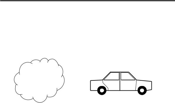
To better understand this concept, consider a vehicle as an object. The most likely description of a vehicle that comes to mind is an object that is used to transport people or goods, perhaps rolling on wheels, with some form of energy to drive it
4 THE OBJECT-ORIENTED APPROACH 59
along (as shown in Figure 4-1 a). A manufacturer cannot proceed to build a vehicle unless they have determined its specific details. Is the vehicle a train, a bus, a car or something else? If it is a car, is it a small car, a medium car or a large car? What is its engine type and capacity? How many doors should it have? This refinement must continue until every detail of the “vehicle to be built” has been defined. At this stage the object is no longer an abstract object. Once completely defined, any number of “cars” can be manufactured as real objects.
Passengers |
Speed |
|
|
|
|
|
Power |
|
Direction |
|
|
Control |
Go |
|
Stop |
|
|
ABSTRACT OBJECT – VEHICLE |
REAL OBJECT – A CAR |
|
(a) |
|
(b) |
Figure 4-1 The concept of abstract objects and real objects.
4.3 Real Objects
Although the cars of this class are identical, when built, they are individual items. Each of these cars will have its own engine, fuel system, braking system, etc. If someone is asked to “Start the engine!”, they cannot start an engine without knowing which car is to be started. Accordingly, the word “engine” does not uniquely identify “an engine”. To be able to do so, the engine must be tagged with a particular car. For example, suppose three cars have been built and they are labelled A, B, and C. Then “Engine of Car A” will uniquely identify an engine. Thus, while “Car” is an object type, “Car A” is an actual object. It is important to understand the difference between the object type and the actual object. The existence of an object type does not necessarily mean that actual objects of that type exist. However, an actual object cannot exist without having its object type in existence.
The terms such as engine, fuel system, braking system, etc. can be used to generally describe those systems. For example, to describe features of the engine of a particular car type, we do not have to say the engine of the ‘blue’ car has such
60 4 THE OBJECT-ORIENTED APPROACH
and such features. We would simply say engines of this particular car type have these features. On the other hand, if an engine of a car is faulty, we must specifically refer to that car by saying ‘the engine of that blue car’ is faulty and needs to be repaired. Therefore, when an object type is described, we can use its terms without having to tag them to a physical object.
4.3.1 Public Interface of an Object
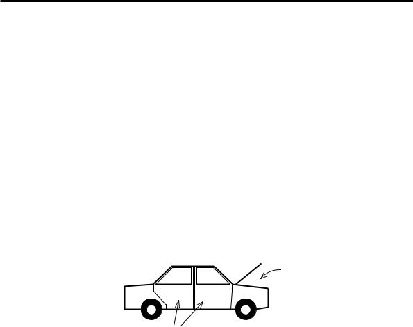
A motorcar was a sophisticated object even in early times. There are certain parts of a motorcar that the user is not expected to access; for example, the fuel injection system. The fuel injection system is not directly accessible to the user; nevertheless, it carries out its functions behind the scenes. On the other hand, the driver of the motorcar has direct access to the steering wheel, the brake pedal, the indicator stalk, etc. These can be referred to as the public interface of the object “Car”. Similarly, in object-oriented programming, every object must have a public interface for it to be useful. An object without a public interface is like a perfectly built car, which is completely encased and sealed off so that no one can ever get into it to drive it.
Private or
Protected Space
Public Space
Figure 4-2 The public interface of an object.
The software objects will also have private functions with some designated purpose that are not directly accessed by the users of the object (like the fuel injection system of a motor car). Therefore, in the most general case, an object is an encapsulated entity with a public interface that has restricted access to its hidden details. How objects can be realised in software will be understood as we proceed through the development of object classes in the coming chapters.
4.3.2 Construction and Destruction of Objects
All cars come to life through some kind of a manufacturing process, which we may refer to as the “construction process”. If needed there can be slight variations to the cars built according to the ‘same’ plan – for example, cars that have different colour. Furthermore, manufacturing processes themselves could be slightly different. In one factory, cars may be built starting from sub-assemblies. In another

4 THE OBJECT-ORIENTED APPROACH 61
factory, cars may be built from scratch. In either case, the same type of car will be produced.
After the car has been brought to physical reality, it can then be driven. At the end of the car’s life it will undergo some sort of destruction process which could take place in a car disposal yard. Destruction is an important process, which carries out the disposal of unwanted items to maintain environmental cleanliness and to allow the efficient management of resources. In the case of computer programs, object destruction is necessary for the efficient management of memory.
The techniques available in object-oriented software development provide mechanisms to realise all these aspects. Although we can draw analologies between the objects in our day-to-day life and the software objects, the real power of objectoriented programming in C++ comes from the combination of object-oriented programming techniques and C++ programming techniques.
4.4 Object Classes
An object class describes a particular type of object. The object class does not refer to a real object but the type of those real objects yet to be created. If we take an analogy from everyday life; a building plan is analogous to an object class – not the building itself. The same building plan can be used to create any number of buildings. Likewise, the same object class can be used to create any number of objects. Each object that will be created according to an object class will reside in the memory of your computer. If more objects of the same type are created, more memory will be used.
Member Data
Member Functions
Constructors &
Destructors
Figure 4-3 Components of an object class.